EP0614100A2 - Optische Vorrichtung zur Veränderung von Brennpunkt und Brennweite - Google Patents
Optische Vorrichtung zur Veränderung von Brennpunkt und Brennweite Download PDFInfo
- Publication number
- EP0614100A2 EP0614100A2 EP94102530A EP94102530A EP0614100A2 EP 0614100 A2 EP0614100 A2 EP 0614100A2 EP 94102530 A EP94102530 A EP 94102530A EP 94102530 A EP94102530 A EP 94102530A EP 0614100 A2 EP0614100 A2 EP 0614100A2
- Authority
- EP
- European Patent Office
- Prior art keywords
- cam
- lens group
- focal length
- optical axis
- lens
- Prior art date
- Legal status (The legal status is an assumption and is not a legal conclusion. Google has not performed a legal analysis and makes no representation as to the accuracy of the status listed.)
- Granted
Links
- 230000003287 optical effect Effects 0.000 title claims abstract description 56
- 230000007246 mechanism Effects 0.000 claims abstract description 29
- 238000006073 displacement reaction Methods 0.000 claims abstract description 13
- 230000004044 response Effects 0.000 claims abstract description 13
- 230000008859 change Effects 0.000 claims description 9
- 238000000034 method Methods 0.000 description 3
- 238000004519 manufacturing process Methods 0.000 description 2
- 238000012986 modification Methods 0.000 description 2
- 230000004048 modification Effects 0.000 description 2
- 230000000717 retained effect Effects 0.000 description 2
- 230000000712 assembly Effects 0.000 description 1
- 238000000429 assembly Methods 0.000 description 1
- 238000003384 imaging method Methods 0.000 description 1
Images


Classifications
-
- G—PHYSICS
- G02—OPTICS
- G02B—OPTICAL ELEMENTS, SYSTEMS OR APPARATUS
- G02B7/00—Mountings, adjusting means, or light-tight connections, for optical elements
- G02B7/02—Mountings, adjusting means, or light-tight connections, for optical elements for lenses
- G02B7/04—Mountings, adjusting means, or light-tight connections, for optical elements for lenses with mechanism for focusing or varying magnification
- G02B7/10—Mountings, adjusting means, or light-tight connections, for optical elements for lenses with mechanism for focusing or varying magnification by relative axial movement of several lenses, e.g. of varifocal objective lens
Definitions
- the present invention relates to the field of photography and is directed to optical apparatus for varying the focal length and adjusting the focus of a multi-focal lens system.
- Modern cameras frequently include optical systems, sometimes called zoom lenses, having multiple or infinitely variable focal lengths ranging from wide-angle to telephoto. It is common in such optical systems to include lens groups that are moveable relative to each other along the optical axis to change the focal length of the system. When the focal length is changed, it is desirable at the same time to maintain focus throughout the entire range of focal lengths. This adjustment usually is accomplished by moving the optical elements relative to the film or other imaging plane.
- an elbow linkage couples first and second lens groups in a pancratic objective system.
- the linkage includes a cam follower at the elbow for engaging and following a cam surface so that axial movement of the first lens group extends or contracts the linkage, changing the distance between the lens groups and the system focal length.
- Optical systems that simultaneously change the focus and focal length, and particularly zoom lenses that include a cam and follower mechanism, such as those described above, are particularly sensitive to design and manufacturing tolerances. Axial movement of the lens groups, intended to focus the system, simultaneously is translated by the cam and follower mechanism into relative displacement of the lens groups, changing the focal length. In automated cameras that include switches and motors for driving the focusing mechanism, relatively precise alignment and tolerances are required, not only in the cam and follower mechanism, but throughout the position sensing and switching actuators.
- the present invention is directed to apparatus having first and second lens groups moveable along an optical axis, and including a cam and follower mechanism for changing the focal length of the optical system by communicating relative axial displacement to said second lens group in response to axial movement of said first lens group.
- the cam and follower mechanism is characterized by a plurality of cam steps, each having first means for maintaining said relative axial displacement constant in response to axial movement of said first lens group, and second means for changing said relative axial displacement in response to axial movement of said first lens group.
- the first means includes a dwell cam surface extending parallel to the optical axis for accommodating axial movement of said first lens group to permit focusing of the optical system between at least two focus positions at a fixed focal length
- the second means includes a ramped cam surface extending at an angle to the optical axis for displacing said second lens group relative to said first lens group in response to axial movement of said first lens group , thereby to change the focal length of the optical system.
- the cam and follower mechanism includes a plurality of opposed pairs of cam steps, each pair including dwell cam surfaces extending parallel to each other and the optical axis, and ramped cam surfaces extending at an angle relative to each other and the optical axis.
- the invention is disclosed in connection with a conventional photographic still camera. Because such cameras are well known, this description is directed in particular to elements forming part of or cooperating directly with the disclosed embodiment.
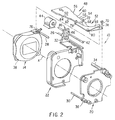
- an optical system in the form of a zoom lens 10 is depicted including first or front and second or back lens groups 12 and 14 , respectively, disposed for relative movement along an optical axis X .
- the front lens group 12 includes a shutter assembly 16 , of conventional design, a front lens retainer 18 and a rear lens retainer 20 , which are all assembled within a lens housing 22 and lens cover or barrel 24 to move as a group along the optical axis.
- the first and second lens groups 12 and 14 can include any number of appropriate combinations of lens elements interposed with shutter and other assemblies suitable for photographic exposures. It also will be apparent that other stationary and moveable groups of optical and related elements can be provided in cooperation with the first and second groups 12 and 14 along the same optical axis.
- the first and second lens groups are maintained in alignment perpendicular to the film plane, are prevented from rotating, and are mounted for lengthwise movement along the optical axis by a plurality of parallel guide rods and anti-rotation shafts 26 , 28 , and 30 .
- Main shaft 26 is secured to the camera body (not shown), and extends through a bushing 32 in housing 22 for aligning the first lens group 12 relative to the camera body and film plane (not shown).
- Shaft 28 extends from the second lens group 14 through an aperture in housing 22 and into a sleeve 34 in the first lens group 12 for maintaining proper alignment of the second lens group 14 relative to the first lens group 12.
- Shaft 30 extends from a boss 36 in the first lens group 12 through the housing 22 and against a notch 38 in the second lens group 14 to prevent rotation of the second lens group 14 relative to the first lens group 12.
- the end of the anti-rotation shaft adjacent retainer 18 is accommodated by a notch 40 in the retainer.
- the drive shaft 42 is coupled to housing 22 through a threaded nut 46 that translates rotary movement of the drive shaft into longitudinal movement of the housing and the first lens group assembled therewith.
- the second lens group 14, is moveable independently of the first lens group along shafts 28 and 30.
- the focus adjustment and focal length selection for the optical system are varied by a control device 48 which extends between and is coupled to the first and second lens groups 12 and 14.
- the control device includes a cam and cam follower mechanism 50 and 52 , respectively, for changing the focal length of the optical system by communicating relative axial displacement to said second lens group in response to axial movement of said first lens group.
- the cam and follower mechanism includes a plurality of cam steps depicted at 54 , and 56 , each having a dwell cam surface 58 extending parallel to the optical axis, and a ramped cam surface 60 , extending at an angle to the optical axis.
- the dwell cam surface accommodates axial movement of said first lens group without changing the relative displacement between the lens groups and thereby permits focusing of the optical system between at least two focus positions at a fixed focal length.
- the ramped cam surface displaces said second lens group relative to said first lens group in response to movement of said first lens group along the optical axis, and thereby changes the focal length of the optical system.
- the cam and follower mechanism also includes a second plurality of cam steps 62 and 64 that are essentially mirror images of the steps 54 and 56 to define opposed pairs of cam steps, where each pair includes dwell cam surfaces that extend parallel to each other and to the optical axis, and ramped cam surfaces that extend at an angle relative to each other and the optical axis.
- the cam follower 52 includes first and second linkages in the form of L-shaped members 66 and 68 .
- the first L-shaped member 66 includes one end pivotally coupled to the front lens group 12 through a pin 70 , and another end having a cam follower in the form of a pin 72 .
- the second L-shaped member 68 has one end coupled to the second lens group 14 through a pin 74 and slot 76 (Fig. 2), permitting translational movement there between.
- Another end of second L-shaped member 68 includes a cam follower in the form of a pin 78 .
- the first and second L-shaped members form a scissors linkage coupled in their center sections by a floating pivot 80 .
- cam followers 72 and 78 are urged under the influence of spring 82 (Fig. 1) into engagement with the opposed cam surfaces of cam 50 for controlling a number of important optical functions. These functions will be described in connection with the operation of the cam and follower mechanism which follows.
- the focal length is set first by selective operation of motor 44 to rotate drive shaft 42, operating through nut 46, to translate the rotary motion of the drive shaft into movement of the first lens group along optical axis X.
- the first and second cam followers 72 and 78 are ramped apart by divergent cam surfaces that are angled away from each other and relative to the optical axis. This ramping movement spreads the cam followers and pivots the scissors linkage 66 and 68 apart, thereby displacing the second lens group relative to the first lens group. Both groups move along the same axis, but by a different amount, thereby changing the focal length.
- the focus can then be adjusted using the very same motor, drive shaft and mechanism to shift the first lens group so cam followers 72 and 78 transverse the cam sections that are parallel to each other and the optical axis.
- Such movement does not change the separating of the cam followers or the relative displacement between the first and second lens groups and, therefor, does not change the focal length of the optical system, It does, however, change its focus, permitting two or more focus settings for each discrete focal length.
- Such a cam and follower mechanism can be utilized to accomplish a number of different valuable objectives.
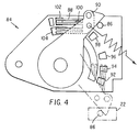
- a switch control assembly 84 is depicted for use with the present invention to sense and control the relative position of the first lens group 12 as it moves between a wide-angle position, depicted in solid lines in Fig. 4, and a telephoto position, depicted in phantom in Fig. 4.
- a pin 86 carried by housing 22 moves with the first lens group 12 during changes in its position along optical axis X. During such movement the pin engages and sweeps contacts 88 , on pivotal arm 90 , across a plurality of switch pads 92 , 94 , 96 , 98 , 100 , and 102 , for establishing electrical connections between such switch pads and a grounding strip 104 .
- Each switch pad represents a desired position along the optical axis of the first lens group and cooperates with appropriate electrical mechanisms in the camera body (not shown) and motor 44 to establish the first lens group in each desired position.
- the dimensions of the respective pads also can be chosen in cooperation with the dwell and ramp surfaces 58 and 60 of the cam and follower mechanism 48 and 50 to facilitate the operation already described.
- the above-described embodiment can be used with a simple switch (not shown) for setting close-up and distance focus settings.
- the apparatus When in the close-up setting, the apparatus will drive the first lens group to a position at each discrete focal length that is suitable for close-up pictures.
- the apparatus When in the distance setting, on the other hand, the apparatus will drive the first lens group to a different position, at each discrete focal length, that is suitable for distance pictures.
- an auto-focus device can be substituted for the manual switch to employ the same cam and follower mechanism to focus the camera. The focal length is selected first, and then the auto-focus device can be actuated to use the dwell cam surface to change focus without altering the focal length.
- a cam and follower mechanism in accordance with the invention can be used to permit relaxation of manufacturing tolerances and specifications. Somewhat imprecise location of the first lens group would still result in relatively precise selection of a discrete focal length. The simplicity of a cam and follower arrangement would be retained while removing the prior art requirement of relatively precise tolerances.
Landscapes
- Physics & Mathematics (AREA)
- General Physics & Mathematics (AREA)
- Optics & Photonics (AREA)
- Lens Barrels (AREA)
- Focusing (AREA)
- Automatic Focus Adjustment (AREA)
Applications Claiming Priority (2)
| Application Number | Priority Date | Filing Date | Title |
|---|---|---|---|
| US08/024,033 US5333024A (en) | 1993-03-01 | 1993-03-01 | Optical apparatus for changing focus and focal length |
| US24033 | 1993-03-01 |
Publications (3)
| Publication Number | Publication Date |
|---|---|
| EP0614100A2 true EP0614100A2 (de) | 1994-09-07 |
| EP0614100A3 EP0614100A3 (de) | 1995-12-27 |
| EP0614100B1 EP0614100B1 (de) | 1999-05-26 |
Family
ID=21818494
Family Applications (1)
| Application Number | Title | Priority Date | Filing Date |
|---|---|---|---|
| EP94102530A Expired - Lifetime EP0614100B1 (de) | 1993-03-01 | 1994-02-19 | Optische Vorrichtung zur Veränderung von Brennpunkt und Brennweite |
Country Status (5)
| Country | Link |
|---|---|
| US (1) | US5333024A (de) |
| EP (1) | EP0614100B1 (de) |
| JP (1) | JPH06294923A (de) |
| DE (1) | DE69418631T2 (de) |
| ES (1) | ES2131599T3 (de) |
Families Citing this family (15)
| Publication number | Priority date | Publication date | Assignee | Title |
|---|---|---|---|---|
| US5365298A (en) * | 1993-04-05 | 1994-11-15 | Eastman Kodak Company | Camera shutter with oscillation damping |
| JP3435580B2 (ja) * | 1993-04-30 | 2003-08-11 | コニカ株式会社 | ズームレンズ鏡胴及びカメラ |
| US5708886A (en) * | 1993-08-23 | 1998-01-13 | Fuji Photo Optical Co., Ltd. | Camera |
| US5940178A (en) * | 1996-07-03 | 1999-08-17 | Beckman Instruments, Inc. | Nephelometer and turbidimeter combination |
| AU750602B2 (en) * | 1996-07-03 | 2002-07-25 | Beckman Coulter, Inc. | Nephelometer and turbidimeter combination |
| US5825559A (en) * | 1997-06-27 | 1998-10-20 | Eastman Kodak Company | Optical assembly having a dual purpose focus |
| US6011657A (en) * | 1998-05-05 | 2000-01-04 | Eastman Kodak Company | Optical apparatus for changing focus and focal length |
| JP3720227B2 (ja) * | 2000-01-31 | 2005-11-24 | 松下電器産業株式会社 | 撮像装置 |
| JP4311874B2 (ja) * | 2000-12-07 | 2009-08-12 | パナソニック株式会社 | フランジバック調整機構付きカメラ |
| JP2005234050A (ja) * | 2004-02-17 | 2005-09-02 | Sigma Koki Kk | 光学部品保持ユニット |
| KR100985928B1 (ko) * | 2008-08-25 | 2010-10-06 | 삼성전기주식회사 | 카메라 장치 |
| US7961401B1 (en) * | 2009-12-23 | 2011-06-14 | Ge Inspection Technologies, Lp | System for providing two position zoom-focus |
| DE102012215295B4 (de) | 2012-08-29 | 2016-06-02 | Carl Zeiss Meditec Ag | Verstellvorrichtung für ein optisches System |
| JP6284374B2 (ja) * | 2014-01-24 | 2018-02-28 | オリンパス株式会社 | レンズ鏡筒 |
| JP6707791B2 (ja) | 2017-05-09 | 2020-06-10 | エスゼット ディージェイアイ テクノロジー カンパニー リミテッドSz Dji Technology Co.,Ltd | 光量調整装置、撮像装置、撮像システム、及び移動体 |
Family Cites Families (17)
| Publication number | Priority date | Publication date | Assignee | Title |
|---|---|---|---|---|
| US1988367A (en) * | 1932-02-23 | 1935-01-15 | Uhertype Ag | Copying camera |
| DE1104211B (de) * | 1959-04-22 | 1961-04-06 | Schneider Co Optische Werke | Einrichtung an photographischen, kinematographischen, Vergroesserungs-, Reproduktions- oder Fernseh-Objektiven mit axial beweglichen optischen Gliedern |
| DE8003643U1 (de) * | 1980-02-12 | 1980-05-08 | Fa. Carl Zeiss, 7920 Heidenheim | Verstellvorrichtung fuer ein pankratisches objektiv eines stereomikroskops |
| JPS59228636A (ja) * | 1983-06-10 | 1984-12-22 | Konishiroku Photo Ind Co Ltd | 自動焦点調節装置付カメラのプログラム自動露出制御装置 |
| US5005038A (en) * | 1983-10-11 | 1991-04-02 | Canon Kabushiki Kaisha | Focal length changeable camera |
| US4887109A (en) * | 1987-05-27 | 1989-12-12 | Fuji Photo Film Co. Ltd. | Viewfinder for a camera with changeable focal length |
| US4757372A (en) * | 1987-10-09 | 1988-07-12 | Eastman Kodak Company | SLR zoom camera |
| JPH0814679B2 (ja) * | 1987-11-16 | 1996-02-14 | 富士写真光機株式会社 | 沈胴式ズームレンズ付カメラ |
| JPH01161326A (ja) * | 1987-12-18 | 1989-06-26 | Asahi Optical Co Ltd | 焦点距離可変レンズのレンズ移動機構 |
| US4971427A (en) * | 1988-03-18 | 1990-11-20 | Fuji Photo Film Co., Ltd. | Zoom lens drive mechanism of a camera |
| JP2524455Y2 (ja) * | 1988-06-01 | 1997-01-29 | 旭光学工業株式会社 | ズームレンズのカム構造 |
| US4990945A (en) * | 1988-08-13 | 1991-02-05 | Fuji Photo Film Co., Ltd. | Camera of changeable focal length |
| US4980711A (en) * | 1988-11-04 | 1990-12-25 | Fuji Photo Film Co., Ltd. | Camera with zooming mechanism |
| US5146254A (en) * | 1989-04-19 | 1992-09-08 | Ricoh Company, Ltd. | Apparatus for driving varifocal lens |
| JP2782636B2 (ja) * | 1990-02-26 | 1998-08-06 | 富士写真フイルム株式会社 | ビデオカメラ |
| JPH04136908A (ja) * | 1990-09-28 | 1992-05-11 | Fuji Photo Optical Co Ltd | ズームレンズの初期焦点調整機構 |
| US5349476A (en) * | 1993-03-01 | 1994-09-20 | Eastman Kodak Company | Control for optical system having multiple focal lengths |
-
1993
- 1993-03-01 US US08/024,033 patent/US5333024A/en not_active Expired - Fee Related
-
1994
- 1994-02-19 EP EP94102530A patent/EP0614100B1/de not_active Expired - Lifetime
- 1994-02-19 ES ES94102530T patent/ES2131599T3/es not_active Expired - Lifetime
- 1994-02-19 DE DE69418631T patent/DE69418631T2/de not_active Expired - Fee Related
- 1994-03-01 JP JP6031329A patent/JPH06294923A/ja active Pending
Also Published As
| Publication number | Publication date |
|---|---|
| US5333024A (en) | 1994-07-26 |
| EP0614100B1 (de) | 1999-05-26 |
| ES2131599T3 (es) | 1999-08-01 |
| DE69418631D1 (de) | 1999-07-01 |
| DE69418631T2 (de) | 1999-12-02 |
| EP0614100A3 (de) | 1995-12-27 |
| JPH06294923A (ja) | 1994-10-21 |
Similar Documents
| Publication | Publication Date | Title |
|---|---|---|
| US5333024A (en) | Optical apparatus for changing focus and focal length | |
| US6752542B2 (en) | Lens shutter mechanism | |
| EP0116210B1 (de) | Vorrichtung zur Bewegung einer optischen Linse | |
| US5345287A (en) | Apparatus for correcting parallax and/or diopter of camera | |
| US5349476A (en) | Control for optical system having multiple focal lengths | |
| US5444485A (en) | Camera with turret lens and solid state image sensor | |
| US4763999A (en) | Zoom lens assembly | |
| US4955715A (en) | Psuedo format camera | |
| EP0783129B1 (de) | Optisches Gerät | |
| US5339126A (en) | Zoom lens barrel | |
| US6906871B2 (en) | Cam mechanism for lens barrel | |
| US5689739A (en) | Lens drive mechanism for photographic camera with zoom lens | |
| US6011657A (en) | Optical apparatus for changing focus and focal length | |
| US4618253A (en) | Focal position adjusting device for small variable-magnification type copying machine with zoom lens | |
| US5367355A (en) | Flash ready condition dependent on focal length | |
| JP2003222946A (ja) | カメラ | |
| US6839187B2 (en) | Lens distance-varying mechanism, and step-zoom lens incorporating the same | |
| JPH0119121B2 (de) | ||
| JPH1020173A (ja) | カメラのズームレンズ鏡筒 | |
| JP2000075190A (ja) | レンズ鏡筒およびこれを備えた光学機器 | |
| JPH0833510B2 (ja) | 焦点距離が切換可能なレンズ構体 | |
| EP0654698A1 (de) | Kamera mit Porträtsbetriebsart | |
| US6954587B2 (en) | Switching/moving structure of a zoom lens | |
| JP2003149528A (ja) | 撮影レンズユニットおよび電子カメラ | |
| JP2535931B2 (ja) | レンズ鏡筒の信号切換装置 |
Legal Events
| Date | Code | Title | Description |
|---|---|---|---|
| PUAI | Public reference made under article 153(3) epc to a published international application that has entered the european phase |
Free format text: ORIGINAL CODE: 0009012 |
|
| AK | Designated contracting states |
Kind code of ref document: A2 Designated state(s): BE CH DE ES FR GB IT LI NL |
|
| PUAL | Search report despatched |
Free format text: ORIGINAL CODE: 0009013 |
|
| AK | Designated contracting states |
Kind code of ref document: A3 Designated state(s): BE CH DE ES FR GB IT LI NL |
|
| 17P | Request for examination filed |
Effective date: 19960608 |
|
| 17Q | First examination report despatched |
Effective date: 19960919 |
|
| GRAG | Despatch of communication of intention to grant |
Free format text: ORIGINAL CODE: EPIDOS AGRA |
|
| GRAG | Despatch of communication of intention to grant |
Free format text: ORIGINAL CODE: EPIDOS AGRA |
|
| GRAH | Despatch of communication of intention to grant a patent |
Free format text: ORIGINAL CODE: EPIDOS IGRA |
|
| GRAH | Despatch of communication of intention to grant a patent |
Free format text: ORIGINAL CODE: EPIDOS IGRA |
|
| GRAA | (expected) grant |
Free format text: ORIGINAL CODE: 0009210 |
|
| ITF | It: translation for a ep patent filed | ||
| AK | Designated contracting states |
Kind code of ref document: B1 Designated state(s): BE CH DE ES FR GB IT LI NL |
|
| REG | Reference to a national code |
Ref country code: CH Ref legal event code: EP |
|
| REF | Corresponds to: |
Ref document number: 69418631 Country of ref document: DE Date of ref document: 19990701 |
|
| REG | Reference to a national code |
Ref country code: ES Ref legal event code: FG2A Ref document number: 2131599 Country of ref document: ES Kind code of ref document: T3 |
|
| REG | Reference to a national code |
Ref country code: CH Ref legal event code: NV Representative=s name: KIRKER & CIE SA |
|
| ET | Fr: translation filed | ||
| PGFP | Annual fee paid to national office [announced via postgrant information from national office to epo] |
Ref country code: ES Payment date: 20000216 Year of fee payment: 7 |
|
| PG25 | Lapsed in a contracting state [announced via postgrant information from national office to epo] |
Ref country code: BE Free format text: LAPSE BECAUSE OF NON-PAYMENT OF DUE FEES Effective date: 20000228 |
|
| PG25 | Lapsed in a contracting state [announced via postgrant information from national office to epo] |
Ref country code: LI Free format text: LAPSE BECAUSE OF NON-PAYMENT OF DUE FEES Effective date: 20000229 Ref country code: CH Free format text: LAPSE BECAUSE OF NON-PAYMENT OF DUE FEES Effective date: 20000229 |
|
| PLBE | No opposition filed within time limit |
Free format text: ORIGINAL CODE: 0009261 |
|
| STAA | Information on the status of an ep patent application or granted ep patent |
Free format text: STATUS: NO OPPOSITION FILED WITHIN TIME LIMIT |
|
| 26N | No opposition filed | ||
| BERE | Be: lapsed |
Owner name: EASTMAN KODAK CY Effective date: 20000228 |
|
| PG25 | Lapsed in a contracting state [announced via postgrant information from national office to epo] |
Ref country code: NL Free format text: LAPSE BECAUSE OF NON-PAYMENT OF DUE FEES Effective date: 20000901 |
|
| REG | Reference to a national code |
Ref country code: CH Ref legal event code: PL |
|
| NLV4 | Nl: lapsed or anulled due to non-payment of the annual fee |
Effective date: 20000901 |
|
| PG25 | Lapsed in a contracting state [announced via postgrant information from national office to epo] |
Ref country code: ES Free format text: LAPSE BECAUSE OF NON-PAYMENT OF DUE FEES Effective date: 20010220 |
|
| REG | Reference to a national code |
Ref country code: GB Ref legal event code: IF02 |
|
| REG | Reference to a national code |
Ref country code: ES Ref legal event code: FD2A Effective date: 20020916 |
|
| PGFP | Annual fee paid to national office [announced via postgrant information from national office to epo] |
Ref country code: GB Payment date: 20030106 Year of fee payment: 10 |
|
| PGFP | Annual fee paid to national office [announced via postgrant information from national office to epo] |
Ref country code: FR Payment date: 20030204 Year of fee payment: 10 |
|
| PGFP | Annual fee paid to national office [announced via postgrant information from national office to epo] |
Ref country code: DE Payment date: 20030228 Year of fee payment: 10 |
|
| PG25 | Lapsed in a contracting state [announced via postgrant information from national office to epo] |
Ref country code: GB Free format text: LAPSE BECAUSE OF NON-PAYMENT OF DUE FEES Effective date: 20040219 |
|
| PG25 | Lapsed in a contracting state [announced via postgrant information from national office to epo] |
Ref country code: DE Free format text: LAPSE BECAUSE OF NON-PAYMENT OF DUE FEES Effective date: 20040901 |
|
| GBPC | Gb: european patent ceased through non-payment of renewal fee |
Effective date: 20040219 |
|
| PG25 | Lapsed in a contracting state [announced via postgrant information from national office to epo] |
Ref country code: FR Free format text: LAPSE BECAUSE OF NON-PAYMENT OF DUE FEES Effective date: 20041029 |
|
| REG | Reference to a national code |
Ref country code: FR Ref legal event code: ST |
|
| PG25 | Lapsed in a contracting state [announced via postgrant information from national office to epo] |
Ref country code: IT Free format text: LAPSE BECAUSE OF NON-PAYMENT OF DUE FEES;WARNING: LAPSES OF ITALIAN PATENTS WITH EFFECTIVE DATE BEFORE 2007 MAY HAVE OCCURRED AT ANY TIME BEFORE 2007. THE CORRECT EFFECTIVE DATE MAY BE DIFFERENT FROM THE ONE RECORDED. Effective date: 20050219 |