EP0614833A2 - Procédé et dispositif pour convoyer des articles, notamment pour installations automatiques d'emballage - Google Patents
Procédé et dispositif pour convoyer des articles, notamment pour installations automatiques d'emballage Download PDFInfo
- Publication number
- EP0614833A2 EP0614833A2 EP94102692A EP94102692A EP0614833A2 EP 0614833 A2 EP0614833 A2 EP 0614833A2 EP 94102692 A EP94102692 A EP 94102692A EP 94102692 A EP94102692 A EP 94102692A EP 0614833 A2 EP0614833 A2 EP 0614833A2
- Authority
- EP
- European Patent Office
- Prior art keywords
- articles
- rows
- row
- plate
- flow lines
- Prior art date
- Legal status (The legal status is an assumption and is not a legal conclusion. Google has not performed a legal analysis and makes no representation as to the accuracy of the status listed.)
- Granted
Links
Images
Classifications
-
- B—PERFORMING OPERATIONS; TRANSPORTING
- B65—CONVEYING; PACKING; STORING; HANDLING THIN OR FILAMENTARY MATERIAL
- B65G—TRANSPORT OR STORAGE DEVICES, e.g. CONVEYORS FOR LOADING OR TIPPING, SHOP CONVEYOR SYSTEMS OR PNEUMATIC TUBE CONVEYORS
- B65G47/00—Article or material-handling devices associated with conveyors; Methods employing such devices
- B65G47/22—Devices influencing the relative position or the attitude of articles during transit by conveyors
- B65G47/26—Devices influencing the relative position or the attitude of articles during transit by conveyors arranging the articles, e.g. varying spacing between individual articles
-
- B—PERFORMING OPERATIONS; TRANSPORTING
- B65—CONVEYING; PACKING; STORING; HANDLING THIN OR FILAMENTARY MATERIAL
- B65B—MACHINES, APPARATUS OR DEVICES FOR, OR METHODS OF, PACKAGING ARTICLES OR MATERIALS; UNPACKING
- B65B35/00—Supplying, feeding, arranging or orientating articles to be packaged
- B65B35/30—Arranging and feeding articles in groups
- B65B35/44—Arranging and feeding articles in groups by endless belts or chains
-
- B—PERFORMING OPERATIONS; TRANSPORTING
- B65—CONVEYING; PACKING; STORING; HANDLING THIN OR FILAMENTARY MATERIAL
- B65G—TRANSPORT OR STORAGE DEVICES, e.g. CONVEYORS FOR LOADING OR TIPPING, SHOP CONVEYOR SYSTEMS OR PNEUMATIC TUBE CONVEYORS
- B65G47/00—Article or material-handling devices associated with conveyors; Methods employing such devices
- B65G47/02—Devices for feeding articles or materials to conveyors
- B65G47/04—Devices for feeding articles or materials to conveyors for feeding articles
- B65G47/06—Devices for feeding articles or materials to conveyors for feeding articles from a single group of articles arranged in orderly pattern, e.g. workpieces in magazines
- B65G47/08—Devices for feeding articles or materials to conveyors for feeding articles from a single group of articles arranged in orderly pattern, e.g. workpieces in magazines spacing or grouping the articles during feeding
- B65G47/082—Devices for feeding articles or materials to conveyors for feeding articles from a single group of articles arranged in orderly pattern, e.g. workpieces in magazines spacing or grouping the articles during feeding grouping articles in rows
Definitions
- the present invention relates to a process for conveying articles supplied in respective flow lines adjacent to one another.
- the invention has been developed with particular attention to the possible use in the field of plants for automatically packaging products, such as food products, for example confectionery products.
- the source stations can be packaging machines in which products such as snacks, biscuits, etc., packaged in flexible wrappers (flow-packs), are inserted in groups in respective boxes.
- the further processing stations can, for example, be wrapping machines in which each box is in turn inserted in a further wrapping in the form of a flexible wrapper of the flow-pack type.
- the source stations usually supply a conveying line with parallel rows.
- Each source machine supplies a respective row with a flow of articles which, although it is substantially constant, is not completely continuous, owing to the various reasons: for example, temporary stoppages of the source station because of a lack of packaging material, discharge of defective articles upstream or downstream of the source station, etc..
- the number of source stations and thus of the parallel rows of the flow of articles generated thereby is generally different from the number of processing stations provided downstream.
- ten source stations for example, ten boxing machines
- the object of the present invention is to provide a process which can overcome the above problems, on the one hand, avoiding great stresses on the articles processed and, on the other hand, minimising the need for recourse to an accumulation zone, thus reducing the space occupied by the packaging plant.
- a further object of the invention is a device for performing the above process.
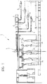
- Figure 1 shows the planimetric development (so-called layout) of a plant for automatically packaging articles such as, for example, food products, in particular confectionery products as a general plan view.
- the articles in question consist of products such as snacks, bars of chocolate, biscuits or stacks of biscuits in respective packages in the form of flexible wrappers (for example, of the type currently known as "flow-pack") and arranged in groups in respective containers such as parallelepipedal cardboard boxes. These boxes are filled in respective "source stations” M provided, in the embodiment illustrated, in groups of ten.
- the structure of the source stations M (usually consisting, in cascade, of a first wrapping machine of the flow-pack type followed by a boxing machine proper) is widely known in the art and, as such, need not be described in detail here, since it is also irrelevant with respect to an understanding of the invention.
- the source stations M supply the respective packaged articles onto an output line L typically consisting of an assembly of conveyors (for example, chain or belt conveyors) which define a respective flow line of articles for each station M.
- an output line L typically consisting of an assembly of conveyors (for example, chain or belt conveyors) which define a respective flow line of articles for each station M.
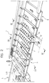
- the output end of the line L (shown in particular on the lefthand side of Figure 2) can be viewed as a conveyor such as, for example, a motor-driven belt conveyor on which the articles A are in their respective advancing lines indicated L1 to L10.
- the operation of the device according to the invention is usually such that it allows the articles A to be fed in a flow, which is as regular as possible, therefore timed exactly and without interruptions in continuity, towards respective handling stations situated downstream, generally indicated G.
- the stations G can consist of wrapping machines for wrapping each article A (and thus each box) in a respective flexible wrapper (flow-pack).
- both the choice of the number of stations G relative to the number of stations M and the adoption of an operating arrangement with master stations and auxiliary stations and the relative positioning of these stations should be considered as factors which generally have no influence on the structure of the device 1, in the sense that the device 1 can be arranged such that it serves any number of upstream stations M and downstream stations G, independently of the operating strategy adopted for the latter and as regards the spatial arrangement thereof.
- the device 1 is arranged such that it receives the articles A which arrive at the output end of the line L arranged end-to-end, that is, in such a way that the articles A, on the device 1, tend initially to follow an advancing path aligned with the advancing paths of the lines L1, ..., L10.
- the same device 1 should then transfer the articles A to the lines G located downstream by a movement (initially of adjustment and then of net translation) which develops in a direction generally transverse the advancing directions on the line L and entry into the device 1.
- the device 1 substantially consists of a plate 2 usually consisting of a metal plate mounted in a fixed position on a casing 3 and extending, in normal operating conditions, in a generally horizontal direction.
- a conveyor device consisting, in a preferred embodiment, of two lateral motor-driven members 3 located along the longer sides of the plate 2, acts above the plate 2.
- each of the members 3 consists of a chain (or a similar flexible element) which is wound - in known manner - about respective end rollers (not shown in the drawing, but located at the upstream and downstream ends of the plate 2 respectively) with an active pass 3a extending horizontally above the plate 2 and a return pass located above or below the plate 2.
- Rectilinear entrainment elements 5 consisting, for example, of sheets or strips 5 extend between the two chains 3 in a direction generally transverse the arrival direction of the articles A on the device 1.
- the strips 5 are supported at their ends by the active passes 3a of the chains 3 and generally extend downwards (towards the plate 2 but usually without touching it) in a position of interference with the articles A which are on the plate itself.
- the articles A situated on the plate itself are subjected to a thrust movement (brushing) causing the articles A, which arrive on the plate 2 scattered (that is, in a flow which is quite irregular relative to the advancing direction on the line L), to give rise to an ordered sequence of rows of articles A which advance on the plate 2.
- the term "row” is intended to define a line of articles A aligned in a direction transverse the direction of advance on the line L with the rear side of the articles bearing on a respective motor-driven strip 5 which advances the articles A onto the plate 2 (continuously or, better, in steps).
- the rows are generally incomplete: see in this respect the end of the device 1 which is further to the left in Figure 2.
- the advance of the articles A along the paths L1, ..., L10 is not totally free of spaces or breaks in continuity.
- the presence of a space or a break in continuity on any of the paths L1,..., L10 is manifested by a corresponding space in the row of articles A which is to be formed on the device 2.
- the articles A are preferably transferred on the device 1 (and, in particular, on the plate 2) when they have been subjected to a first action in which they are at least partially arranged in rows.
- an ordering element such as a further strip or barrier 6 with associated drive means (not illustrated but of a widely known type) which support the barrier 6 such that it is periodically lowered from above towards the outlet end of the line L such that a given number of articles arriving on the line L accumulate against it, arranging these articles in order - at least approximately - in a line intended to form a respective row of articles being transferred on the device 1.
- the device 1 intervenes in order to render the row compact, that is, it moves the articles A in each row towards one another which leads to the elimination of any existing spaces (for example, if there is a lack of articles in the flow on one or more of the supply paths L1,..., L10) between adjacent articles.
- a stopping structure 7 is provided consisting, for example, of a side made of sheet metal which extends along the corresponding longitudinal edge of the plate 2 in a position such that it interferes with the plate 2 itself, preferably with a lower edge part 4a, turned under the plane of the plate 2, and extending at approximately the same height as the plate 2 itself.
- a transverse movable element emerges, through a respective window, which, in the example illustrated, consists of a further belt conveyor 8 having an upper pass 8a which acts horizontally and is aligned exactly with the plane of the plate 2 and a lower pass 8b situated below the plane of the plate 2 itself.
- the belt 8 is wound (according to a widely known solution) on end pulleys or rollers 9 with associated drive elements 9a (of a widely known type). When they are actuated, the rollers or pulleys 9 move the belt 8 itself such that the upper pass 8a follows a net translation path in the direction transverse the direction of advance of the rows of articles A controlled by the strips 5.
- the net effect of the advance of the upper pass 8a is to carry the articles A, combined in a row but spaced apart from each other (even irregularly if there are spaces because of shortages in the supply on the respective conveying line L1, ..., L10), to move gradually against the side plate 7 so as to form a compact row, that is to say, an array in which all the articles A are adjacent one another, without spaces, forming a line which bears at one end against the side plate 7: it will be appreciated that the above occurs whilst the articles A continue their longitudinal sliding movement on the plate 2 under the action of the strips 5.
- this advance movement (and hence the actuation movement of the strips 5, controlled by the chains 3 in the example illustrated) can occur continuously or in steps, according to the solution preferred at the time.
- the gradual compacting movement of the row by virtue of the resistance from the side plate 7 can be performed very gradually and smoothly, that is, by the effect of a translation movement of the upper pass 8a of the motor-driven belt 8 at reduced speed, if there is an initial acceleration ramp and a corresponding final deceleration ramp which avoids great stresses which could damage the articles A being applied thereto.
- the articles A By virtue of the gradual advance along the plate 2 controlled by the strips 5, the articles A, now arranged in compact rows, travel beyond the position in which the belt 8 acts and pass to one (or more) withdrawal station (s) arranged in cascade.
- Figure 2 shows the structure of one of these withdrawal stations, that is to say, in the example illustrated, the station which is in the most upstream position relative to the device 2: this is the withdrawal station intended to supply the processing station G located further upstream, in the direction of flow of the articles A within the scope of the plant according to Figure 1.
- the withdrawal station generally indicated 10, has a structure which, to a certain degree, is similar to the structure adopted for performing the lateral compacting action of the rows by the belt 8.
- the sliding surface defined by the plate 2 has a rectangular window in which the further motor-driven belt conveyor 11 extends horizontally, this belt conveyor having an upper pass 11a, aligned exactly with the plane of the plate 2, and a lower, return pass 11b located below the plate 2 itself, with end rollers 12 which control the advance movement of the upper pass 11a of the conveyor in the direction which discharges the articles A from the device 1.
- the side plate 7 has an aperture (indicated 7a in Figure 1) in correspondence with the withdrawal station 10.
- a further difference with respect to the assembly arrangement of the conveyor-compacting device 8 is provided by the fact that the withdrawal conveyor 11 does not extend over the entire transverse dimension of the plate 2 but, on the contrary, only over a portion or recess corresponding to the width (measured in the direction transverse the direction of advance imparted by the strips 5) of a given number of articles A (for example, with reference to the example illustrated, three articles A).
- the movement of the conveyor 11 is such that three (or, in general, n ) articles A are withdrawn by the device 1 so as to be sent on an outlet conveyor C constituting the feed conveyor of a respective actuating station G.
- the conveyor C is also formed by a motor-driven-type endless belt having a loading or upstream end C situated in the immediate vicinity of the outlet end, indicated 11c, of the conveyor 11.
- each of the withdrawal stations 10 to tap a predetermined given number (3, in the example illustrated here) of articles A from the rows A advancing on the plate 2, transversely to the direction of advance of the rows.
- the withdrawal action thus performed determines the removal, so to speak, of an end or head part within the scope of the row of articles A.
- the rows of articles A advance towards a further lateral translation device consisting of a belt 8 arranged in a manner substantially similar to that described above and the operation of which is to bring the remainder of the line back into contact with the side plate 7 so as to return a given number of articles A into the vicinity of the side plate 7 itself.
- the solution described has the advantage of being able to minimise (possibly reducing it to one unit) the number of articles A which are tapped from time to time from the device 1 in order to advance towards a respective processing station G.
- This enables a precise regulation or regularisation of the flow of articles towards the processing stations G to be achieved, which, in turn, enables the presence of accumulation zones (storage) in the feed lines of these machines to be reduced and virtually eliminated.
Landscapes
- Engineering & Computer Science (AREA)
- Mechanical Engineering (AREA)
- Attitude Control For Articles On Conveyors (AREA)
- Packaging Of Special Articles (AREA)
- Container Filling Or Packaging Operations (AREA)
- Filtering Of Dispersed Particles In Gases (AREA)
- Supplying Of Containers To The Packaging Station (AREA)
- Auxiliary Devices For And Details Of Packaging Control (AREA)
- Waveguide Switches, Polarizers, And Phase Shifters (AREA)
- Paper (AREA)
- Manufacture Of Iron (AREA)
- Confectionery (AREA)
- Seeds, Soups, And Other Foods (AREA)
Applications Claiming Priority (2)
| Application Number | Priority Date | Filing Date | Title |
|---|---|---|---|
| CH750/93 | 1993-03-12 | ||
| CH00750/93A CH688823A5 (it) | 1993-03-12 | 1993-03-12 | Procedimento e dispositivo per il convogliamento di articoli, particolarmente per impianti automatici di confezionamento. |
Publications (3)
| Publication Number | Publication Date |
|---|---|
| EP0614833A2 true EP0614833A2 (fr) | 1994-09-14 |
| EP0614833A3 EP0614833A3 (fr) | 1995-01-18 |
| EP0614833B1 EP0614833B1 (fr) | 1997-06-04 |
Family
ID=4194332
Family Applications (1)
| Application Number | Title | Priority Date | Filing Date |
|---|---|---|---|
| EP94102692A Expired - Lifetime EP0614833B1 (fr) | 1993-03-12 | 1994-02-23 | Procédé et dispositif pour convoyer des articles, notamment pour installations automatiques d'emballage |
Country Status (22)
| Country | Link |
|---|---|
| US (1) | US5396980A (fr) |
| EP (1) | EP0614833B1 (fr) |
| AT (1) | ATE153975T1 (fr) |
| BG (1) | BG61759B1 (fr) |
| CH (1) | CH688823A5 (fr) |
| CZ (1) | CZ52994A3 (fr) |
| DE (1) | DE69403514T2 (fr) |
| DK (1) | DK0614833T3 (fr) |
| EE (1) | EE03153B1 (fr) |
| ES (1) | ES2104203T3 (fr) |
| GR (1) | GR3024172T3 (fr) |
| HR (1) | HRP940169B1 (fr) |
| HU (1) | HU216391B (fr) |
| LT (1) | LT3212B (fr) |
| LV (1) | LV11162B (fr) |
| PL (1) | PL172867B1 (fr) |
| RO (1) | RO117611B1 (fr) |
| RU (1) | RU2125011C1 (fr) |
| SG (1) | SG43988A1 (fr) |
| SI (1) | SI9400125A (fr) |
| SK (1) | SK279527B6 (fr) |
| YU (1) | YU48616B (fr) |
Cited By (1)
| Publication number | Priority date | Publication date | Assignee | Title |
|---|---|---|---|---|
| CN103950579A (zh) * | 2014-04-29 | 2014-07-30 | 佘峰 | 一种履带包装机的引导装置 |
Families Citing this family (11)
| Publication number | Priority date | Publication date | Assignee | Title |
|---|---|---|---|---|
| US6189300B1 (en) * | 1999-08-02 | 2001-02-20 | Tuan Vinh Le | Wrapping machine |
| JP2001225029A (ja) * | 2000-02-18 | 2001-08-21 | Hiroshi Maeda | オンライン内部品質検査用搬送装置 |
| US7017730B2 (en) * | 2000-05-12 | 2006-03-28 | Lockheed Martin Corporation | Bi-directional mail tray pusher |
| FR2814729B1 (fr) * | 2000-10-02 | 2003-01-10 | Cogema | Procede et dispositif pour reguler l'espacement et la vitesse d'objets cheminant de facon aleatoire |
| SE519011C2 (sv) * | 2001-05-31 | 2002-12-23 | Tetra Laval Holdings & Finance | Anordning för kontinuerlig gruppering av föremål på en transportbana |
| US7048622B2 (en) * | 2002-02-04 | 2006-05-23 | Conagra Foods, Inc. | Automated laterally offset retractable food dislodgement or guiding mechanisms and associated methods and systems |
| ITTO20070766A1 (it) * | 2007-10-26 | 2009-04-27 | Soremartec Sa | "dispositivo per ridurre il disallineamento fra prodotti convogliati e relativo procedimento" |
| US7726461B2 (en) * | 2008-08-12 | 2010-06-01 | Laitram, L.L.C. | Apparatuses and methods for controlling the spacing of and ejecting conveyed objects |
| WO2019025904A1 (fr) * | 2017-07-31 | 2019-02-07 | Dematic Corp. | Trieuse d'articles à évacuation active |
| FI130923B1 (en) * | 2018-05-04 | 2024-05-29 | Actiw Oy | Grouping station for grouping pallets |
| IT202000023044A1 (it) | 2020-09-30 | 2022-03-30 | Azionaria Costruzioni Acma Spa | Metodo e dispositivo per l’alimentazione di articoli |
Family Cites Families (19)
| Publication number | Priority date | Publication date | Assignee | Title |
|---|---|---|---|---|
| US2804961A (en) * | 1954-03-16 | 1957-09-03 | Meyer Geo J Mfg Co | Conveyor apparatus for articleprocessing units |
| US2833393A (en) * | 1956-09-25 | 1958-05-06 | Lamb Co F Jos | Distributing conveyor arrangements |
| DE1291282C2 (de) * | 1964-02-19 | 1975-02-06 | Vorrichtung zum befoerdern von schokoladetafeln oder -riegeln | |
| US3429416A (en) * | 1967-07-18 | 1969-02-25 | Package Machinery Co | Transfer conveyor apparatus for candy bars and the like |
| US3463291A (en) * | 1967-10-20 | 1969-08-26 | Nat Biscuit Co | Article aligning and row accumulating apparatus |
| US3513629A (en) | 1967-12-08 | 1970-05-26 | Nat Biscuit Co | Overwrap packing machines |
| DE1611893A1 (de) * | 1968-01-04 | 1971-01-14 | Theegarten Franz | Verpackungsanlage fuer Pralinen,schokoladenueberzogene Bonbons u.dgl. |
| CH498027A (de) * | 1968-08-29 | 1970-10-31 | Azionaria Costruzioni Acma Spa | Einrichtung zur Ableitung von Produkten von einer Ausgabemaschine zu Aufnahmemaschinen |
| US3669240A (en) * | 1971-02-18 | 1972-06-13 | Del Monte Corp | Method and apparatus for orienting articles |
| DD90511A1 (fr) * | 1971-07-21 | 1972-06-05 | ||
| DE2161618A1 (de) * | 1971-12-11 | 1973-06-14 | Haensel Otto Gmbh | Verfahren und vorrichtung zum beschikken von mehreren, an einem gemeinsamen zubringer angeschlossenen arbeitsstationen mit suesswarenstuecken |
| AU496775B2 (en) * | 1975-07-22 | 1978-10-26 | Hans Lingl | Rearranging rows of articles |
| US4197935A (en) | 1976-06-07 | 1980-04-15 | Fmc Corporation | Automatic feeding of spaced articles to a processing machine |
| US4192416A (en) * | 1977-04-01 | 1980-03-11 | NIKO Konserven-Maschinenfabrik Hinsbek GmbH & Co., KG | Device for transferring piece material, in particular pieces of fruit or vegetable |
| DE3630791C1 (de) * | 1986-09-10 | 1987-10-22 | Bahlsens Keksfabrik | Verfahren und Vorrichtung zum Foerdern stueckiger Gueter und zum organisierten Veraendern ihrer Lage |
| IT1222101B (it) * | 1987-07-23 | 1990-08-31 | Vortex Systems Srl | Apparecchiatura per l' ordinazione e la creazione di un accumulo di alimentazione in impianto di inscatolamento di coni e/o conoidi |
| GB8807586D0 (en) * | 1988-03-30 | 1988-05-05 | Burton S Gold Medal Biscuits | Improvements in & relating to apparatus for automatically reorganising product lines |
| SU1692916A1 (ru) * | 1989-12-06 | 1991-11-23 | Территориальное Производственное Объединение Хлебопекарных И Макаронных Предприятий "Новосибирскхлебпром" | Устройство дл поворота и распределени изделий |
| IT1253225B (it) * | 1991-10-24 | 1995-07-11 | Azionaria Costruzioni Acma Spa | Unita' compattatrice di gruppi di prodotti appiattiti disposti affiancati di taglio |
-
1993
- 1993-03-12 CH CH00750/93A patent/CH688823A5/it not_active IP Right Cessation
-
1994
- 1994-02-23 SG SG1996008706A patent/SG43988A1/en unknown
- 1994-02-23 AT AT94102692T patent/ATE153975T1/de active
- 1994-02-23 DE DE69403514T patent/DE69403514T2/de not_active Expired - Fee Related
- 1994-02-23 EP EP94102692A patent/EP0614833B1/fr not_active Expired - Lifetime
- 1994-02-23 DK DK94102692.4T patent/DK0614833T3/da not_active Application Discontinuation
- 1994-02-23 ES ES94102692T patent/ES2104203T3/es not_active Expired - Lifetime
- 1994-03-01 LT LTIP1887A patent/LT3212B/lt not_active IP Right Cessation
- 1994-03-04 US US08/205,501 patent/US5396980A/en not_active Expired - Lifetime
- 1994-03-08 YU YU10194A patent/YU48616B/sh unknown
- 1994-03-09 HU HU9400702A patent/HU216391B/hu not_active IP Right Cessation
- 1994-03-09 LV LVP-94-48A patent/LV11162B/en unknown
- 1994-03-09 CZ CZ94529A patent/CZ52994A3/cs unknown
- 1994-03-10 BG BG98648A patent/BG61759B1/bg unknown
- 1994-03-10 SK SK300-94A patent/SK279527B6/sk unknown
- 1994-03-10 PL PL94302544A patent/PL172867B1/pl unknown
- 1994-03-11 RO RO94-00406A patent/RO117611B1/ro unknown
- 1994-03-11 SI SI9400125A patent/SI9400125A/sl unknown
- 1994-03-11 HR HR00750/93-5A patent/HRP940169B1/xx not_active IP Right Cessation
- 1994-03-11 RU RU94007637A patent/RU2125011C1/ru active
- 1994-05-23 EE EE9400018A patent/EE03153B1/xx unknown
-
1997
- 1997-07-18 GR GR970401817T patent/GR3024172T3/el unknown
Cited By (1)
| Publication number | Priority date | Publication date | Assignee | Title |
|---|---|---|---|---|
| CN103950579A (zh) * | 2014-04-29 | 2014-07-30 | 佘峰 | 一种履带包装机的引导装置 |
Also Published As
| Publication number | Publication date |
|---|---|
| GR3024172T3 (en) | 1997-10-31 |
| DK0614833T3 (da) | 1997-09-01 |
| HUT69876A (en) | 1995-09-28 |
| EP0614833A3 (fr) | 1995-01-18 |
| BG98648A (bg) | 1995-06-30 |
| LV11162B (en) | 1996-10-20 |
| CZ52994A3 (en) | 1995-02-15 |
| HU9400702D0 (en) | 1994-06-28 |
| HRP940169A2 (en) | 1996-08-31 |
| LT3212B (en) | 1995-04-25 |
| LTIP1887A (en) | 1994-10-25 |
| SK279527B6 (sk) | 1998-12-02 |
| PL172867B1 (pl) | 1997-12-31 |
| HU216391B (hu) | 1999-06-28 |
| EP0614833B1 (fr) | 1997-06-04 |
| ES2104203T3 (es) | 1997-10-01 |
| YU10194A (sh) | 1997-01-08 |
| RO117611B1 (ro) | 2002-05-30 |
| DE69403514T2 (de) | 1997-10-02 |
| EE03153B1 (et) | 1999-02-15 |
| ATE153975T1 (de) | 1997-06-15 |
| RU2125011C1 (ru) | 1999-01-20 |
| HRP940169B1 (en) | 1997-12-31 |
| LV11162A (lv) | 1996-04-20 |
| US5396980A (en) | 1995-03-14 |
| SG43988A1 (en) | 1997-11-14 |
| CH688823A5 (it) | 1998-04-15 |
| YU48616B (sh) | 1999-03-04 |
| SK30094A3 (en) | 1995-01-12 |
| SI9400125A (en) | 1994-09-30 |
| DE69403514D1 (de) | 1997-07-10 |
| BG61759B1 (bg) | 1998-05-29 |
Similar Documents
| Publication | Publication Date | Title |
|---|---|---|
| EP0614833B1 (fr) | Procédé et dispositif pour convoyer des articles, notamment pour installations automatiques d'emballage | |
| EP0331210B1 (fr) | Procédé et dispositif pour l'introduction dans des récipients d'emballages en feuilles remplis d'un produit sans forme fixe | |
| US5133446A (en) | Device for the formation and transfer of groups of commodities | |
| US8474598B2 (en) | Device and method for composing packages for a packaging machine | |
| JP2006321567A (ja) | 連続作動包装装置 | |
| EP0634322A1 (fr) | Procédé pour alimenter des groupes d'articles de tabac, spécialement des cigarettes, à une machine d'emballage à opération continue | |
| US4443995A (en) | Metering device and method | |
| ITMI930314A1 (it) | Procedimento e dispositivo per il confezionamento di oggetti in un processo a funzionamento continuo | |
| JP2763181B2 (ja) | ティッシュペーパーの小型パックのグループのハンドル形態をなす大型ユニット製品の製造装置 | |
| JP2000515835A (ja) | 複数列で供給される製品を受け取ってパイリングし、得られた製品のパイルを包装ラインへ運搬する方法及び装置 | |
| EP2731870B1 (fr) | Usine permettant d'emballer des produits en bandes, tels que des chewing-gums, et procédé d'emballage correspondant | |
| US5619843A (en) | Film wrap machine | |
| US7017324B2 (en) | Machine for producing strip packages | |
| CN211810371U (zh) | 包装设备和用于薄膜区段的运输装置 | |
| JP4853052B2 (ja) | グルーピング装置 | |
| EP0317198A2 (fr) | Systèmes et procédés d'emballage | |
| JP2022527238A (ja) | 紙ロールを包装するためのシステム及び操作方法。 | |
| EP1992562B1 (fr) | Unité pour former des groupes de produits pour des lignes d'emballage et procédé correspondant | |
| US2686543A (en) | Conveyer system | |
| EP0905065B1 (fr) | Poste pour la formation de piles d'objets et pour leur transport à une machine | |
| EP0077302B1 (fr) | Méthode et dispositif pour emballer plusieurs produits alimentaires enveloppés séparément | |
| EP0457792B1 (fr) | Procede et appareil pour l'emballage de sacs plats, de sachets et autres objets similaires | |
| JPH0516904A (ja) | 箱詰システムと該システムに使用される箱詰装置及び上蓋被装装置 | |
| GB2053828A (en) | Selectively transferring packages between sets of conveyors | |
| JPH0314404A (ja) | 製品の供給の一時中断装置 |
Legal Events
| Date | Code | Title | Description |
|---|---|---|---|
| PUAI | Public reference made under article 153(3) epc to a published international application that has entered the european phase |
Free format text: ORIGINAL CODE: 0009012 |
|
| AK | Designated contracting states |
Kind code of ref document: A2 Designated state(s): AT BE CH DE DK ES FR GB GR IE IT LI LU MC NL PT SE |
|
| PUAL | Search report despatched |
Free format text: ORIGINAL CODE: 0009013 |
|
| AK | Designated contracting states |
Kind code of ref document: A3 Designated state(s): AT BE CH DE DK ES FR GB GR IE IT LI LU MC NL PT SE |
|
| RAP1 | Party data changed (applicant data changed or rights of an application transferred) |
Owner name: FERRERO OFFENE HANDELSGESELLSCHAFT M.B.H. Owner name: FERRERO S.P.A. Owner name: SOREMARTEC S.A. |
|
| 17P | Request for examination filed |
Effective date: 19950204 |
|
| 17Q | First examination report despatched |
Effective date: 19951208 |
|
| GRAG | Despatch of communication of intention to grant |
Free format text: ORIGINAL CODE: EPIDOS AGRA |
|
| GRAH | Despatch of communication of intention to grant a patent |
Free format text: ORIGINAL CODE: EPIDOS IGRA |
|
| GRAH | Despatch of communication of intention to grant a patent |
Free format text: ORIGINAL CODE: EPIDOS IGRA |
|
| GRAA | (expected) grant |
Free format text: ORIGINAL CODE: 0009210 |
|
| AK | Designated contracting states |
Kind code of ref document: B1 Designated state(s): AT BE CH DE DK ES FR GB GR IE IT LI LU MC NL PT SE |
|
| REF | Corresponds to: |
Ref document number: 153975 Country of ref document: AT Date of ref document: 19970615 Kind code of ref document: T |
|
| ITF | It: translation for a ep patent filed | ||
| REG | Reference to a national code |
Ref country code: CH Ref legal event code: NV Representative=s name: JACOBACCI & PERANI S.A. Ref country code: CH Ref legal event code: EP |
|
| REF | Corresponds to: |
Ref document number: 69403514 Country of ref document: DE Date of ref document: 19970710 |
|
| ET | Fr: translation filed | ||
| REG | Reference to a national code |
Ref country code: DK Ref legal event code: T3 |
|
| REG | Reference to a national code |
Ref country code: GR Ref legal event code: FG4A Free format text: 3024172 |
|
| REG | Reference to a national code |
Ref country code: ES Ref legal event code: FG2A Ref document number: 2104203 Country of ref document: ES Kind code of ref document: T3 |
|
| REG | Reference to a national code |
Ref country code: PT Ref legal event code: SC4A Free format text: AVAILABILITY OF NATIONAL TRANSLATION Effective date: 19970710 |
|
| PLBE | No opposition filed within time limit |
Free format text: ORIGINAL CODE: 0009261 |
|
| STAA | Information on the status of an ep patent application or granted ep patent |
Free format text: STATUS: NO OPPOSITION FILED WITHIN TIME LIMIT |
|
| 26N | No opposition filed | ||
| PGFP | Annual fee paid to national office [announced via postgrant information from national office to epo] |
Ref country code: MC Payment date: 20000118 Year of fee payment: 7 |
|
| PGFP | Annual fee paid to national office [announced via postgrant information from national office to epo] |
Ref country code: SE Payment date: 20010109 Year of fee payment: 8 |
|
| PGFP | Annual fee paid to national office [announced via postgrant information from national office to epo] |
Ref country code: AT Payment date: 20010110 Year of fee payment: 8 |
|
| PGFP | Annual fee paid to national office [announced via postgrant information from national office to epo] |
Ref country code: DK Payment date: 20010112 Year of fee payment: 8 |
|
| PGFP | Annual fee paid to national office [announced via postgrant information from national office to epo] |
Ref country code: IE Payment date: 20010118 Year of fee payment: 8 |
|
| PGFP | Annual fee paid to national office [announced via postgrant information from national office to epo] |
Ref country code: ES Payment date: 20010119 Year of fee payment: 8 |
|
| PGFP | Annual fee paid to national office [announced via postgrant information from national office to epo] |
Ref country code: CH Payment date: 20010122 Year of fee payment: 8 |
|
| PGFP | Annual fee paid to national office [announced via postgrant information from national office to epo] |
Ref country code: PT Payment date: 20010123 Year of fee payment: 8 |
|
| PGFP | Annual fee paid to national office [announced via postgrant information from national office to epo] |
Ref country code: NL Payment date: 20010129 Year of fee payment: 8 Ref country code: GR Payment date: 20010129 Year of fee payment: 8 |
|
| PGFP | Annual fee paid to national office [announced via postgrant information from national office to epo] |
Ref country code: LU Payment date: 20010205 Year of fee payment: 8 |
|
| PG25 | Lapsed in a contracting state [announced via postgrant information from national office to epo] |
Ref country code: MC Free format text: LAPSE BECAUSE OF NON-PAYMENT OF DUE FEES Effective date: 20010228 |
|
| REG | Reference to a national code |
Ref country code: GB Ref legal event code: IF02 |
|
| PG25 | Lapsed in a contracting state [announced via postgrant information from national office to epo] |
Ref country code: LU Free format text: LAPSE BECAUSE OF NON-PAYMENT OF DUE FEES Effective date: 20020223 Ref country code: AT Free format text: LAPSE BECAUSE OF NON-PAYMENT OF DUE FEES Effective date: 20020223 |
|
| PG25 | Lapsed in a contracting state [announced via postgrant information from national office to epo] |
Ref country code: SE Free format text: LAPSE BECAUSE OF NON-PAYMENT OF DUE FEES Effective date: 20020224 |
|
| PG25 | Lapsed in a contracting state [announced via postgrant information from national office to epo] |
Ref country code: IE Free format text: LAPSE BECAUSE OF NON-PAYMENT OF DUE FEES Effective date: 20020225 Ref country code: ES Free format text: LAPSE BECAUSE OF NON-PAYMENT OF DUE FEES Effective date: 20020225 |
|
| PG25 | Lapsed in a contracting state [announced via postgrant information from national office to epo] |
Ref country code: LI Free format text: LAPSE BECAUSE OF NON-PAYMENT OF DUE FEES Effective date: 20020228 Ref country code: DK Free format text: LAPSE BECAUSE OF NON-PAYMENT OF DUE FEES Effective date: 20020228 Ref country code: CH Free format text: LAPSE BECAUSE OF NON-PAYMENT OF DUE FEES Effective date: 20020228 |
|
| PG25 | Lapsed in a contracting state [announced via postgrant information from national office to epo] |
Ref country code: PT Free format text: LAPSE BECAUSE OF NON-PAYMENT OF DUE FEES Effective date: 20020831 |
|
| PG25 | Lapsed in a contracting state [announced via postgrant information from national office to epo] |
Ref country code: NL Free format text: LAPSE BECAUSE OF NON-PAYMENT OF DUE FEES Effective date: 20020901 |
|
| PG25 | Lapsed in a contracting state [announced via postgrant information from national office to epo] |
Ref country code: GR Free format text: LAPSE BECAUSE OF NON-PAYMENT OF DUE FEES Effective date: 20020909 |
|
| EUG | Se: european patent has lapsed |
Ref document number: 94102692.4 |
|
| REG | Reference to a national code |
Ref country code: CH Ref legal event code: PL |
|
| REG | Reference to a national code |
Ref country code: DK Ref legal event code: EBP |
|
| NLV4 | Nl: lapsed or anulled due to non-payment of the annual fee |
Effective date: 20020901 |
|
| REG | Reference to a national code |
Ref country code: PT Ref legal event code: MM4A Free format text: LAPSE DUE TO NON-PAYMENT OF FEES Effective date: 20020831 |
|
| REG | Reference to a national code |
Ref country code: IE Ref legal event code: MM4A |
|
| REG | Reference to a national code |
Ref country code: ES Ref legal event code: FD2A Effective date: 20031022 |
|
| PGFP | Annual fee paid to national office [announced via postgrant information from national office to epo] |
Ref country code: DE Payment date: 20090225 Year of fee payment: 16 |
|
| PGFP | Annual fee paid to national office [announced via postgrant information from national office to epo] |
Ref country code: GB Payment date: 20090219 Year of fee payment: 16 |
|
| PGFP | Annual fee paid to national office [announced via postgrant information from national office to epo] |
Ref country code: IT Payment date: 20090212 Year of fee payment: 16 |
|
| PGFP | Annual fee paid to national office [announced via postgrant information from national office to epo] |
Ref country code: BE Payment date: 20090408 Year of fee payment: 16 |
|
| PGFP | Annual fee paid to national office [announced via postgrant information from national office to epo] |
Ref country code: FR Payment date: 20090227 Year of fee payment: 16 |
|
| BERE | Be: lapsed |
Owner name: S.A. *SOREMARTEC Effective date: 20100228 |
|
| GBPC | Gb: european patent ceased through non-payment of renewal fee |
Effective date: 20100223 |
|
| REG | Reference to a national code |
Ref country code: FR Ref legal event code: ST Effective date: 20101029 |
|
| PG25 | Lapsed in a contracting state [announced via postgrant information from national office to epo] |
Ref country code: FR Free format text: LAPSE BECAUSE OF NON-PAYMENT OF DUE FEES Effective date: 20100301 |
|
| PG25 | Lapsed in a contracting state [announced via postgrant information from national office to epo] |
Ref country code: DE Free format text: LAPSE BECAUSE OF NON-PAYMENT OF DUE FEES Effective date: 20100901 Ref country code: BE Free format text: LAPSE BECAUSE OF NON-PAYMENT OF DUE FEES Effective date: 20100228 |
|
| PG25 | Lapsed in a contracting state [announced via postgrant information from national office to epo] |
Ref country code: IT Free format text: LAPSE BECAUSE OF NON-PAYMENT OF DUE FEES Effective date: 20100223 Ref country code: GB Free format text: LAPSE BECAUSE OF NON-PAYMENT OF DUE FEES Effective date: 20100223 |