EP0616861B2 - Presse avec table- et système d'alimentation - Google Patents
Presse avec table- et système d'alimentation Download PDFInfo
- Publication number
- EP0616861B2 EP0616861B2 EP94103285A EP94103285A EP0616861B2 EP 0616861 B2 EP0616861 B2 EP 0616861B2 EP 94103285 A EP94103285 A EP 94103285A EP 94103285 A EP94103285 A EP 94103285A EP 0616861 B2 EP0616861 B2 EP 0616861B2
- Authority
- EP
- European Patent Office
- Prior art keywords
- feed
- plate
- punch
- punching
- feed device
- Prior art date
- Legal status (The legal status is an assumption and is not a legal conclusion. Google has not performed a legal analysis and makes no representation as to the accuracy of the status listed.)
- Expired - Lifetime
Links
Images


Classifications
-
- B—PERFORMING OPERATIONS; TRANSPORTING
- B21—MECHANICAL METAL-WORKING WITHOUT ESSENTIALLY REMOVING MATERIAL; PUNCHING METAL
- B21D—WORKING OR PROCESSING OF SHEET METAL OR METAL TUBES, RODS OR PROFILES WITHOUT ESSENTIALLY REMOVING MATERIAL; PUNCHING METAL
- B21D28/00—Shaping by press-cutting; Perforating
- B21D28/02—Punching blanks or articles with or without obtaining scrap; Notching
- B21D28/06—Making more than one part out of the same blank; Scrapless working
-
- B—PERFORMING OPERATIONS; TRANSPORTING
- B21—MECHANICAL METAL-WORKING WITHOUT ESSENTIALLY REMOVING MATERIAL; PUNCHING METAL
- B21D—WORKING OR PROCESSING OF SHEET METAL OR METAL TUBES, RODS OR PROFILES WITHOUT ESSENTIALLY REMOVING MATERIAL; PUNCHING METAL
- B21D43/00—Feeding, positioning or storing devices combined with, or arranged in, or specially adapted for use in connection with, apparatus for working or processing sheet metal, metal tubes or metal profiles; Associations therewith of cutting devices
- B21D43/003—Positioning devices
-
- B—PERFORMING OPERATIONS; TRANSPORTING
- B21—MECHANICAL METAL-WORKING WITHOUT ESSENTIALLY REMOVING MATERIAL; PUNCHING METAL
- B21D—WORKING OR PROCESSING OF SHEET METAL OR METAL TUBES, RODS OR PROFILES WITHOUT ESSENTIALLY REMOVING MATERIAL; PUNCHING METAL
- B21D43/00—Feeding, positioning or storing devices combined with, or arranged in, or specially adapted for use in connection with, apparatus for working or processing sheet metal, metal tubes or metal profiles; Associations therewith of cutting devices
- B21D43/02—Advancing work in relation to the stroke of the die or tool
- B21D43/04—Advancing work in relation to the stroke of the die or tool by means in mechanical engagement with the work
- B21D43/10—Advancing work in relation to the stroke of the die or tool by means in mechanical engagement with the work by grippers
-
- B—PERFORMING OPERATIONS; TRANSPORTING
- B26—HAND CUTTING TOOLS; CUTTING; SEVERING
- B26D—CUTTING; DETAILS COMMON TO MACHINES FOR PERFORATING, PUNCHING, CUTTING-OUT, STAMPING-OUT OR SEVERING
- B26D5/00—Arrangements for operating and controlling machines or devices for cutting, cutting-out, stamping-out, punching, perforating, or severing by means other than cutting
- B26D5/20—Arrangements for operating and controlling machines or devices for cutting, cutting-out, stamping-out, punching, perforating, or severing by means other than cutting with interrelated action between the cutting member and work feed
- B26D5/30—Arrangements for operating and controlling machines or devices for cutting, cutting-out, stamping-out, punching, perforating, or severing by means other than cutting with interrelated action between the cutting member and work feed having the cutting member controlled by scanning a record carrier
- B26D5/32—Arrangements for operating and controlling machines or devices for cutting, cutting-out, stamping-out, punching, perforating, or severing by means other than cutting with interrelated action between the cutting member and work feed having the cutting member controlled by scanning a record carrier with the record carrier formed by the work itself
-
- B—PERFORMING OPERATIONS; TRANSPORTING
- B26—HAND CUTTING TOOLS; CUTTING; SEVERING
- B26F—PERFORATING; PUNCHING; CUTTING-OUT; STAMPING-OUT; SEVERING BY MEANS OTHER THAN CUTTING
- B26F1/00—Perforating; Punching; Cutting-out; Stamping-out; Apparatus therefor
- B26F1/02—Perforating by punching, e.g. with relatively-reciprocating punch and bed
-
- Y—GENERAL TAGGING OF NEW TECHNOLOGICAL DEVELOPMENTS; GENERAL TAGGING OF CROSS-SECTIONAL TECHNOLOGIES SPANNING OVER SEVERAL SECTIONS OF THE IPC; TECHNICAL SUBJECTS COVERED BY FORMER USPC CROSS-REFERENCE ART COLLECTIONS [XRACs] AND DIGESTS
- Y10—TECHNICAL SUBJECTS COVERED BY FORMER USPC
- Y10T—TECHNICAL SUBJECTS COVERED BY FORMER US CLASSIFICATION
- Y10T83/00—Cutting
- Y10T83/444—Tool engages work during dwell of intermittent workfeed
- Y10T83/445—With work-moving clamp jaw
-
- Y—GENERAL TAGGING OF NEW TECHNOLOGICAL DEVELOPMENTS; GENERAL TAGGING OF CROSS-SECTIONAL TECHNOLOGIES SPANNING OVER SEVERAL SECTIONS OF THE IPC; TECHNICAL SUBJECTS COVERED BY FORMER USPC CROSS-REFERENCE ART COLLECTIONS [XRACs] AND DIGESTS
- Y10—TECHNICAL SUBJECTS COVERED BY FORMER USPC
- Y10T—TECHNICAL SUBJECTS COVERED BY FORMER US CLASSIFICATION
- Y10T83/00—Cutting
- Y10T83/444—Tool engages work during dwell of intermittent workfeed
- Y10T83/4463—Work-sensing means to initiate tool feed
-
- Y—GENERAL TAGGING OF NEW TECHNOLOGICAL DEVELOPMENTS; GENERAL TAGGING OF CROSS-SECTIONAL TECHNOLOGIES SPANNING OVER SEVERAL SECTIONS OF THE IPC; TECHNICAL SUBJECTS COVERED BY FORMER USPC CROSS-REFERENCE ART COLLECTIONS [XRACs] AND DIGESTS
- Y10—TECHNICAL SUBJECTS COVERED BY FORMER USPC
- Y10T—TECHNICAL SUBJECTS COVERED BY FORMER US CLASSIFICATION
- Y10T83/00—Cutting
- Y10T83/444—Tool engages work during dwell of intermittent workfeed
- Y10T83/463—Work-feed element contacts and moves with work
- Y10T83/4632—Comprises a work-moving gripper
-
- Y—GENERAL TAGGING OF NEW TECHNOLOGICAL DEVELOPMENTS; GENERAL TAGGING OF CROSS-SECTIONAL TECHNOLOGIES SPANNING OVER SEVERAL SECTIONS OF THE IPC; TECHNICAL SUBJECTS COVERED BY FORMER USPC CROSS-REFERENCE ART COLLECTIONS [XRACs] AND DIGESTS
- Y10—TECHNICAL SUBJECTS COVERED BY FORMER USPC
- Y10T—TECHNICAL SUBJECTS COVERED BY FORMER US CLASSIFICATION
- Y10T83/00—Cutting
- Y10T83/444—Tool engages work during dwell of intermittent workfeed
- Y10T83/4637—With means to guide, position, or present work to work-feed means
- Y10T83/464—Means to transport work to work-feed means
-
- Y—GENERAL TAGGING OF NEW TECHNOLOGICAL DEVELOPMENTS; GENERAL TAGGING OF CROSS-SECTIONAL TECHNOLOGIES SPANNING OVER SEVERAL SECTIONS OF THE IPC; TECHNICAL SUBJECTS COVERED BY FORMER USPC CROSS-REFERENCE ART COLLECTIONS [XRACs] AND DIGESTS
- Y10—TECHNICAL SUBJECTS COVERED BY FORMER USPC
- Y10T—TECHNICAL SUBJECTS COVERED BY FORMER US CLASSIFICATION
- Y10T83/00—Cutting
- Y10T83/525—Operation controlled by detector means responsive to work
- Y10T83/531—With plural work-sensing means
-
- Y—GENERAL TAGGING OF NEW TECHNOLOGICAL DEVELOPMENTS; GENERAL TAGGING OF CROSS-SECTIONAL TECHNOLOGIES SPANNING OVER SEVERAL SECTIONS OF THE IPC; TECHNICAL SUBJECTS COVERED BY FORMER USPC CROSS-REFERENCE ART COLLECTIONS [XRACs] AND DIGESTS
- Y10—TECHNICAL SUBJECTS COVERED BY FORMER USPC
- Y10T—TECHNICAL SUBJECTS COVERED BY FORMER US CLASSIFICATION
- Y10T83/00—Cutting
- Y10T83/525—Operation controlled by detector means responsive to work
- Y10T83/536—Movement of work controlled
Definitions
- the invention relates to a Press with one Table system and feed system according to the preamble of the claim 1.
- Such systems are used to make panels, for example Steel or aluminum sheet, positioned to feed a press, which a predetermined number of blanks cut out the board.
- suitable feed means which one via gripping or other feed means Grasp the blackboard, the blackboard is gradually moved through Press moved through and during a standstill one Subjected to punching step.
- the feed is usually done along two orthogonal axes because it is cheaper Material utilization an offset division on the Blackboard is chosen.
- US-A-4 382 395 discloses a panel system which a feed carriage has two gripping tongs, which grasp the board on the back edge and gradually advance into the machine tool.
- the feed is coupled to the movement of the machine tool in such a way that the feed takes place at a time when the tool is not closed and therefore outside the Working level.
- the feed carriage travels to an exit or sheet transfer station back, in which he grabs the next board.
- This is carried by a loading carriage from a table alignment station in the correct position in the table takeover position in which the panel is located immediately before the Tool is located.
- the loading carriage moves under the feeder around the metal sheet in the takeover position.
- the drive for the Loading carriage is usually designed so that the Always load the sled into the same slab transfer position brings regardless of their size and the die cut.
- the transfer position corresponds to that Position of the sheet in which a first punching stroke is carried out becomes.
- the gripping means of the second feed device along two orthogonal Axes to make the necessary according to the division of the board To be able to make punchings.
- the invention is therefore based on the object to create a press with a sheet feed and feed system that works without empty strokes of the press, precise alignment allowed a precise feed guaranteed and a lattice with minimal web width enables without Punching and punching on the rear and front edge.
- the press according to the invention is based on one of DE-A-3841683 known press from the two seen in the feed direction rows of tools arranged one behind the other are.
- the tools can be in the feed direction to each other aligned or gapped.
- the system according to the invention uses two feed devices, the first of which is a panel from an alignment station in which the board is precisely oriented or is aligned to reference coordinates.
- Essential to the invention is that the second feed device is the panel only takes over after the press has already had two or more Has performed punching strokes. This way, without idle strokes be driven. However, this means that the plates be pushed forward to the press in such a way that the last stamping step of a board coincides with that first punching step of the next sheet.
- the board - precisely aligned - during the entire punching process in pliers on the massive, yet not punched out side of the board.
- the last one Feed path of the sheet from a suitable feed means e.g. a roller feed. Since it is but only the last step can do all the necessary Corrections are made beforehand. So that can the last panel position by mechanical means in Tool instead of e.g. unsafe roller feed To be defined.
- the pliers can be mounted on rigid mounts and from Spindles are moved so that a high number of cycles is obtained becomes. A clamping edge is not necessary because the feed tongs, who hold the board at the end of processing, are arranged outside.
- the first feed device can return to the starting position by one next table in the alignment station. While of the return stroke, the gripping means are sunk by one Collision with the one subsequently entering the alignment station Avoid blackboard.
- the second gripping means of the second feed device only grasp the panel after the first feed device the board already a few punching steps in the The press has advanced the return stroke of the second gripping means relatively short. This also makes a complete Punching operation guaranteed without idle strokes.
- the drives from the first and second feed device are identified by a numerical Control controlled.
- the numerical control enables a precise movement in time and space, so that even with an extremely unfavorable ratio of Sheet size and number of blanks an idle stroke is avoided.
- the sheets are made with the help of guillotine shears cut from the strip material. This naturally results Tolerances in terms of panel length and angularity the cut edges.
- at least two Sensors are provided which are transverse to the feed direction or axis have a predetermined distance from each other and grasp the front and back edges of a panel and give an appropriate signal.
- the deviation of the front or trailing edge determined from the transverse axis she will in determining the correction factor for the numerical Control can be used as described above. Is the deviation from the exact transverse axis is too large, so that punching out is unavoidable, a stop signal can be generated become. Alternatively, a punch stroke can also be suspended to avoid punching out faulty die cuts.
- the front edge of the board passes both sensors.
- the switch-on edges of both sensors are in relation to the current position of the feed device brought. This position is with a Resolution of 0.01 mm by the measuring system of the NC control detectable. This means that the further feed can be made as required correct the measurement result.
- the leading edge can be related overall brought the way to the tool become. So it is possible regardless of the absolute Length of the board the first punching position while driving adjust there so that no punching or punching occurs. Adjusting the first cutting position of the board in accordance with the response of the sensors via the The path still to be covered serves at a given distance the range of tools and thus the given web width of the Residual lattice, the upper limit for the angularity to be able to set as high as possible. Even with smaller ones Web width of e.g. 0.8 mm should only cover a few panels the limit comes to lie. The existing space between the tool rows are therefore used optimally. Would the panels in a fixed, non-customizable first control position a higher value for the web width be provided.
- the sensors can be transverse to the feed direction or axis have a predetermined distance from each other and the front one and capture the rear edge of a board and a corresponding one Give signal.
- the distance between the sensors is preferably only a little smaller than the width of the panels, to get a high measuring accuracy.
- the numerical Control is a setpoint for the length of the board saved.
- the an actual value for the panel length is calculated for both sensor signals.
- By detecting the front or the rear Edge and the numerical control values determine the exact length of the board. For this are however, very sensitive sensors are required. Therefore proposed according to an embodiment of the invention that they are formed by laser light barriers.
- the on the actual length determined as described above a table is compared with the target value, and from the The difference between the setpoint and actual value becomes a correction value for calculate the following feed steps.
- the position of the feed device in which the leading edge is detected can be specified in relation to a fixed Value to be set as a result of the previous one Alignment of the panel expected for normal panel length becomes. Any deviation from this value shows one Deviation from the nominal board length.
- the web widths within the panel to correct the overall panel length be used.
- the control for the first feed device must be a Undergo correction if a changed length by the Sensors determined and a correction factor calculated has been. If a second feed device is used, which the panel from a first feed device takes over while already in the press, there is a similar change in the feed cut lengths, if a table length deviating from the nominal value is determined has been punched out on the rear Be avoided.
- a stop signal can also be generated if one from the target / actual value comparison of the table length large deviation results, which is certainly too faulty would lead to die cuts.
- the second gripping means are particularly short the second feeder back when after an embodiment of the invention, the board in the transfer position at the back of the board on opposite Capture sides laterally.
- the feed device Before grasping a board by the gripping means of the first The feed device must reference the table with reference coordinates be arranged exactly. This happens in the Alignment station. The board must naturally be replaced by a suitable one Funds are brought into the alignment station. A third feed device is used for this purpose Sheet is conveyed from a loading station to the alignment station. According to one embodiment of the invention, the third Feed device two parallel by separate numerical controlled third actuators Conveyor belts with one driver each. The drivers are arranged so that one behind each one blackboard and the other in front of a blackboard. The in each case the front driver, which is a plate to the alignment station has first been engaged with the front Brought edge of the next board for what he may even have to be moved back again.
- the third feed device can be numerical have driven feed rollers that the panel of capture below and above.
- the pairs of rollers are preferred driven by a single servo motor.
- a first one The pair of rollers is preferably less than one panel length behind the so-called table separation and brakes remove the tablet and hand it over numerically to a second Controlled pair of rollers, which the plate in the alignment station promoted. It brings the board to a standstill and is then preferably moved apart by a few millimeters, so as not to hinder the alignment process.
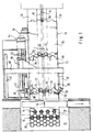
- a press 10 is indicated in FIGS. 1 and 2, whose tools are arranged in two rows 12 and 14.
- the front row 12 seen in the feed direction 16 has five tools, while the back row 14 four tools has that in the gaps of the front tools 12 are arranged.
- the tools actuated simultaneously with a single punch stroke to the to punch out front panel 18 shown in Fig. 1, thereby there are circular die cuts and a so-called Residual grid 20.
- a first feed device 22 has two gripping tongs 24, 26 with which the scrolled Table 18 is detected at the rear edge.
- the pliers 24, 26 are arranged on an arm of a carriage 30 which along guides 32 with the aid of a first adjustment drive 34 is adjustable in the feed direction 16.
- the Gripping tongs 24, 26 can also be adjusted in height, so that on the return stroke they have a subsequent table like the panel 36, do not disturb.
- a second feed device 38 has a carriage 40 on, along guides 42 also in the feed direction 16 can be adjusted.
- the feed drive is used for this 44.
- the carriage 40 supports two arms 46, 48 (In Fig. 1 only the arm 46 is shown for reasons of clarity. For this is the first feed device in Fig. 2 not shown with the exception of the gripping tongs 24, 26).
- Figs. 1 and 2 there is a panel 60 in a feed station 70.
- each conveyor belt 62, 64 has one Driver 66, 68 on.
- a driver or Cam 66 engages the rear edge of a panel 60
- a front driver or cam 68 is located on or in front of the front edge of panel 60.
- the table 60 is removed from the presentation station 70, conveyed to an alignment station 72, in which is the board 36.
- the alignment station 72 is drawn again separately in FIG. 3 to indicate that alignment means (not shown) the panel 36 against two side stops 74, 76 and a rear stop 78 lay.
- alignment means are generally known.
- laser light barriers 80, 82 are in the front Area of the positioning station 72 and 84, 86 in the rear Area indicated.
- the light barrier pairs 80, 82 and 84, 86 have a predetermined distance from each other.
- the Light barriers of a pair 80, 82 and 84, 86 are on one extending perpendicular to the feed axis 16 Transverse axis.
- a pair of light barriers alone, e.g. 80, 82 all necessary Functions fulfilled.
- the presentation device places a board 60 on the surfaces 56, 58 in the reference station, and the Carrier 66 of the conveyor belt 64 promotes the table 60 Alignment station 72, possibly progressing with the Feed the board 36 from the alignment station towards Press 10.
- the alignment takes place in the alignment station 72 the table 36 with the aid of the alignment means, not shown along two orthogonal axes.
- the grippers 24, 26 of the first feed device 22, which during the return stroke of the carriage 30 are lowered to advance a Do not disturb the board to the positioning station, grasp the Panel 36 at the rear end, as dash-dotted lines in FIG. 1 shown.
- the second feed device is pushing 38 with the help of the grippers 50, 52 Plate 18 by the press 10.
- the feed of the plates 36, 18 and the feed devices 22 and 38 are on the numerical control coordinated so that the last die cut the sheet 18 coincides with the first punching of the sheet 36, as shown in Fig. 2.
- the last stamping of the panel 18 is done by the row of tools 12 and the first punching of the new sheet 36 tool row 14. The transition therefore takes place without an idle stroke of the press 10.
- the grippers 50, 52 and Carriage 40 can move back to a starting position, as shown in Fig. 1.
- the grippers 24, 26 the first feed device 22 take over the feed the board 36 by the press 10 for a number of punching steps, e.g. two or more. Therefore the grippers need 50, 52 just a relatively short before the takeover To make the way back, as can be seen from the comparison of the figures 1 and 2 results.
- the advance of the table 18 for the first Part of the punching steps is carried out with the solid ones Lines drawn grippers 24, 26.
- the transition takes place on the second feed device 38 by the Open gripping tongs 24, 26 and gripping tongs 50, 52 conclude.
- This transition takes place during a punch stroke, i.e. immediately during tool engagement with the blackboard, since the blackboard has a fixed position occupies, their situation therefore does not change.
- the second feed device 38 guides the rest Feed steps out until the empty skeleton runs through an ejection device, not shown, for example a driven roller pair can be removed.
- the front edge of the panel 36 crosses the two laser light barriers 80, 82. From their signals or the times of the signals in comparison to the location, the front edge due to the numerically controlled
- the length of the table should have feeds determine and thus the deviation from the target length.
- the feed can now be done by means of a correction value Getting corrected.
- the length of the board also by grasping the trailing edge of panel 36 through the light barriers 84, 86 are determined.
- the path can be determined exactly between crossing the front light barriers 80, 82 and crossing the rear light barriers 84, 86 is. Since the distance between the light barriers 80, 82 on the one hand and 84, 86 on the other hand, can be also in this way the length of the panel 36 or its deviation from the target length.
- the actual length of the determined in the numerical control Table 36 is compared to a stored target length. For example, if panel 36 is slightly shorter than the target length, the numerical control over the feed through the first feed device 22 ensure that the plate 36 is pushed sufficiently far into the press, that in the first stamping step, as shown in Fig. 2, a web remains at the front edge of the board 36, otherwise faulty die cuts will be produced. Therefore calculates the numerical control from the deviation a correction value from the target and actual length of the sheet the feed path or the length of the feed steps accordingly to correct so faulty die cuts cannot be generated. The same applies to the rest Feeding the front panel 18 through the second feed device 38. If the board is too short, on a faulty punching out at the rear end of the board 18 occur.
- Feed device 38 between the punching steps made sure that a web is also on the rear edge stop. For example, this can happen that during that made by the feed device 38 Feed steps each is a little shorter than originally programmed, which also bridges between the die cuts become a bit narrower. Overall, however thereby "gained" a certain length, which for the last punching step ensures that die cuts or Punching on the rear edge does not occur.
- Become only the front light barriers 80, 82 are used by grasping the rear edge of the board Determine the length of the sheet or that for the remaining punching steps remaining table length, um then a feed correction in the manner described above to be able to make.
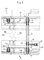
- the system points a frame 90 in which a shaft transverse to the feed direction is rotatably mounted. Sitting on the shaft 92 Distance rotatably two feed rollers 94, 96, and the shaft 92 is driven by a servo motor 98 by a Pinion 100 of the servo motor 98 with a pinion 102 on the Shaft 92 via a toothed belt 104 in drive connection stands.
- Lever arms 106, 108 are rotatable at one end the shaft 92 articulated. At the other end they hold trunnions 110, 112, the feed rollers 114, 116 rotatably.
- the feed rollers 94, 96 are pinions 118, 120 connected, and with the feed rollers 114, 116 are pinions 122, 124 connected.
- the sprockets are about a suitable one Driving means in connection, so that when the Feed rollers 94, 96 also the feed rollers 114, 116 are driven.
- the arms 106, 108 are connected to a lever arm 126, an adjustment cylinder 128 is articulated at the other end thereof is.
- rollers 94, 96 and 114, 116 act with upper rollers together, two of which are shown at 130, 132 in FIG. 5 are. They are on appropriate fixed brackets 134, 136 rotatably mounted. By actuating the adjusting cylinder 128 can the rollers 114, 116 a little after be pivoted below, as indicated by arrow 138.
- the first roller pairs seen in the feed direction are less than the length of a panel 60a behind the panel separation arranged as in Fig. 1 on the right edge of the picture is indicated.
- the plate that is in Fig. 4 is designated 36a, brought to a standstill.
- the adjusting cylinder 128 is then actuated in order to the rollers 114, 116 a little from the upper rollers 130 too remove to align the panel 36a is not disabled.
Landscapes
- Engineering & Computer Science (AREA)
- Mechanical Engineering (AREA)
- Life Sciences & Earth Sciences (AREA)
- Forests & Forestry (AREA)
- Punching Or Piercing (AREA)
- Inking, Control Or Cleaning Of Printing Machines (AREA)
- Measuring Or Testing Involving Enzymes Or Micro-Organisms (AREA)
- Registering Or Overturning Sheets (AREA)
Claims (10)
- Une presse (10) présentant plusieurs outils (12, 14) et comportant un système à dispositif pour plaques et à dispositif d'avance, comportanta) une station d'alignement disposée, dans la direction d'avancement, en avant de la presse (10), station dans laquelle des moyens d'alignement alignent une plaque (36) par rapport à deux axes orthogonaux (74, 76; 78),b) un premier dispositif d'avance (22), comportant des premiers moyens de saisie (24, 26), qui, au moyen d'un premier entraínement de positionnement (34), peuvent être positionnés au moins dans la direction de l'axe d'avancement (16) et qui saisissent, dans une position arrière, une plaque (36) dans la station d'alignement (72) et la font avancer vers la presse,c) un deuxième dispositif d'avance (38) comportant des deuxièmes moyens de saisie (50, 52), qui, au moyen d'un deuxième entraínement de positionnement (44), peuvent être positionnés au moins dans la direction de l'axe d'avancement (16) et qui saisissent, dans une position arrière, une plaque et la font avancer vers la presse,d) la presse (2) présentant deux rangées d'outils (12, 14) placées l'une derrière l'autre, dans la direction d'avancement (16) des plaques (18, 36, 60),
caractérisée par les caractéristiques suivantes:e) le premier dispositif d'avance (22) fait avancer les plaques jusqu'a une position de transfert qui est située, dans la direction de l'avancement, derrière la station d'alignement (72),f) le deuxième dispositif d'avance (38) saisit la plaque dans la position de transfert,g) la position de transfert correspond à la position des plaques (18, 36) pendant une course d'estampage de la presse (10), après que la presse (10) ait déjà effectué au moins une course d'estampage précédente pour une plaque,h) les premier et deuxième dispositifs d'avance (22, 38) agissent ensemble de telle façon que la dernière course de matriçage, effectuée avec la rangée d'outils (12) située en avant dans la direction de l'avancement, pour une première plaque (18), soit en même temps la première course de matriçage effectuée avec la rangée arrière (14) d'outils, pour la plaque suivante (36),i) les deuxièmes moyens de saisie (50, 52) saisissent, sur des côtés opposés, la plaque (18) dans la position de transfert, à l'extrémité arrière de la plaque (18). - Presse suivant la revendication 1, caractérisée en ce qu'avant la station d'alignement (72), est disposée une station de chargement (70) et en ce qu'un troisième dispositif d'avance fait avancer la plaque (60) dans la station d'alignement (72).
- Presse suivant la revendication 2, caractérisée en ce que le troisième dispositif d'avance présente deux bandes parallèles de transport (62, 64), entraínées par des troisièmes entraínements d'avance séparés, à commande numérique, ces bandes de transport comportant chacune un entraíneur (66, 68), et en ce que les entraíneurs (66, 68) sont disposés de telle façon que, chaque fois, l'un se trouve derrière une plaque (60) et que l'autre se trouve avant une plaque (60).
- Presse suivant la revendication 3, caractérisée en ce que la bande transporteuse (62) de chaque entraíneur avant (68) concerné est commandée, pendant l'avance d'une plaque (60) vers la station d'alignement (72), de telle façon que l'entraíneur touche le bord avant de la plaque (60).
- Presse suivant la revendication 2, caractérisée en ce que le troisième dispositif d'avance présente des galets d'avancement (94, 96, 114, 116, 130, 132) placés à une certaine distance les uns des autres dans la direction d'avancement, qui saisissent une plaque (60a, 36a) depuis le haut et le bas, et qui sont entraínés ensemble par un entraínement (98) à commande numérique, la distance entre les galets d'avancement étant plus petite que la longueur d'une plaque (60a, 36a) et les galets d'avancement (114, 116), situés en avant, dans la direction d'avancement, pouvant être écartés du trajet d'avance des plaques (60a, 36a) et étant couplés avec un entraínement de positionnement (128).
- Presse suivant la revendication 5, caractérisée en ce que les galets inférieurs des galets d'avancement avant (114, 116) sont montés sur des bras (106, 108) montés pivotants sur un bâti (90), et en ce qu'au moins un vérin de positionnement (128) agit sur les bras (106, 108).
- Presse suivant l'une des revendications 1 à 6, caractérisée en ce qu'il est prévu au moins deux capteurs (80, 82, 84, 86) qui sont disposés perpendiculairement à la direction d'avancement, à une distance donnée les uns des autres, et qui relèvent la position du bord avant et du bord arrière d'une plaque (36) et émettent un signal correspondant, en ce que, dans un dispositif de commande numérique pour les entraínements (34, 36) de positionnement, est mémorisée une valeur de consigne pour la longueur de la plaque (36), la commande numérique calcule, à partir des signaux des capteurs et des données d'avance provenant de la commande numérique pour le dispositif d'entraínement concerné, une valeur réelle pour la longueur de plaque et la compare avec la valeur de consigne, puis calcule, à partir de la différence entre la valeur de consigne et la valeur réelle, une valeur de correction, avec laquelle est corrigée l'avance résiduaire à effectuer par le premier entraínement de positionnement (34) et l'avance à effectuer par le deuxième entraínement de positionnement (44).
- Presse suivant la revendication 7, caractérisée en ce qu'au moins deux capteurs (80, 82; 84, 86) sont disposés à une certaine distance l'un de l'autre sur un axe transversal, qui est perpendiculaire à l'axe d'avance (16) et ils relèvent la position du bord avant et du bord arrière d'une plaque (36), et leurs signaux servent, dans la commande numérique, à déterminer le décalage des bords de la plaque (36) par rapport à l'axe transversal (angularité).
- Presse suivant la revendication 7 ou la revendication 8, caractérisée en ce que la commande numérique produit un signal d'arrêt si la différence entre la valeur de consigne et la valeur réelle, ou respectivement le décalage par rapport à l'axe transversal, dépasse une valeur prédéfinie.
- Presse suivant l'une des revendications 7 à 9, caractérisée en ce que les capteurs (80, 82, 84, 86) sont constitués par des barrières lumineuses à laser.
Applications Claiming Priority (2)
| Application Number | Priority Date | Filing Date | Title |
|---|---|---|---|
| DE4309949 | 1993-03-26 | ||
| DE19934309949 DE4309949C2 (de) | 1993-03-26 | 1993-03-26 | Tafelanlage- und Vorschubsystem für Pressen |
Publications (3)
| Publication Number | Publication Date |
|---|---|
| EP0616861A1 EP0616861A1 (fr) | 1994-09-28 |
| EP0616861B1 EP0616861B1 (fr) | 1997-12-17 |
| EP0616861B2 true EP0616861B2 (fr) | 2000-09-27 |
Family
ID=6483988
Family Applications (2)
| Application Number | Title | Priority Date | Filing Date |
|---|---|---|---|
| EP94103284A Expired - Lifetime EP0616860B1 (fr) | 1993-03-26 | 1994-03-04 | Presse avec un table et système d'alimentation |
| EP94103285A Expired - Lifetime EP0616861B2 (fr) | 1993-03-26 | 1994-03-04 | Presse avec table- et système d'alimentation |
Family Applications Before (1)
| Application Number | Title | Priority Date | Filing Date |
|---|---|---|---|
| EP94103284A Expired - Lifetime EP0616860B1 (fr) | 1993-03-26 | 1994-03-04 | Presse avec un table et système d'alimentation |
Country Status (5)
| Country | Link |
|---|---|
| US (2) | US5577427A (fr) |
| EP (2) | EP0616860B1 (fr) |
| JP (2) | JP3653108B2 (fr) |
| DE (2) | DE59404798D1 (fr) |
| ES (2) | ES2109528T3 (fr) |
Cited By (1)
| Publication number | Priority date | Publication date | Assignee | Title |
|---|---|---|---|---|
| WO2007113120A1 (fr) * | 2006-03-29 | 2007-10-11 | Frank Hoffmann | Dispositif d'estampage dote d'un systeme d'amenee |
Families Citing this family (24)
| Publication number | Priority date | Publication date | Assignee | Title |
|---|---|---|---|---|
| JP3442590B2 (ja) * | 1995-11-20 | 2003-09-02 | 株式会社アマダ | パンチング加工機およびその加工方法 |
| NL1011077C2 (nl) * | 1999-01-19 | 2000-07-20 | Meco Equip Eng | Werkwijze en inrichting voor het langs een snijlijn(en) van elkaar scheiden van met een gemeenschappelijke drager gevormde producten. |
| DE19920241B4 (de) * | 1999-05-03 | 2006-07-20 | Gebrüder Leonhardt GmbH & Co. KG | Verfahren zum streifenförmigen Verarbeiten von tafelförmigen Werkstücken |
| JP2001062525A (ja) | 1999-08-25 | 2001-03-13 | Matsushita Electric Ind Co Ltd | 薄板型抜き装置 |
| US7168352B2 (en) * | 1999-09-13 | 2007-01-30 | Advanced Semiconductor Engineering, Inc. | Process for sawing substrate strip |
| FI109410B (fi) * | 2000-12-04 | 2002-07-31 | Lillbacka Jetair Oy | Menetelmä ja laitteisto levytyökoneessa |
| PL204386B1 (pl) * | 2001-10-30 | 2010-01-29 | Silgan Holdings Inc | Urządzenie przenośnikowe oraz sposób przenoszenia płyt |
| TW517631U (en) * | 2001-12-14 | 2003-01-11 | Hon Hai Prec Ind Co Ltd | Mold structure for automatic mesh stamping |
| DE10202994B4 (de) * | 2002-01-26 | 2007-10-31 | Alfons Haar, Maschinenbau Gmbh & Co.Kg | Verfahren zum Betreiben eines Tafelanlagesystems für Stanzpressen und Verbindungsmittel zur Durchführung des Verfahrens |
| JP2007031866A (ja) * | 2005-07-25 | 2007-02-08 | Ibiden Co Ltd | 排ガス処理体の保持シール材用打抜板及びそれを用いた保持シール材の製造方法 |
| JP2007260820A (ja) * | 2006-03-28 | 2007-10-11 | Ngk Insulators Ltd | 高アスペクト比な貫孔部を有する工業用部品の製造方法 |
| US8118197B2 (en) | 2007-06-18 | 2012-02-21 | Precision Valve Corporation | Method of making aerosol valve mounting cups and resultant cups |
| FR2976511B1 (fr) * | 2011-06-16 | 2013-07-05 | Peugeot Citroen Automobiles Sa | Dispositif de controle de la position d'un poste intermediaire situe entre deux presses d'une ligne d'emboutissage |
| CN102909284A (zh) * | 2012-10-31 | 2013-02-06 | 山东丽鹏股份有限公司 | 一种冲压板全自动定位装置 |
| CN103358349B (zh) * | 2013-07-12 | 2015-01-07 | 永高股份有限公司 | 双联胶暗箱穿线孔旋转式自动冲压设备 |
| CN103752671B (zh) * | 2014-01-07 | 2016-05-25 | 苏州明捷精密机械有限公司 | 一种圆形冲压件的制作方法 |
| MX394703B (es) | 2014-05-27 | 2025-03-24 | Sacmi | Prensa multi-perforadora. |
| ES2716683T3 (es) * | 2014-12-10 | 2019-06-14 | Gefin Srl | Unidad de troquelado |
| CN104907431A (zh) * | 2015-05-15 | 2015-09-16 | 浙江晨丰科技有限公司 | 一种灯头的上料料道结构 |
| CN106111839A (zh) * | 2016-07-06 | 2016-11-16 | 四川高盛包装制品有限公司 | 一种罐头空罐制盖机 |
| CN106020097B (zh) * | 2016-07-06 | 2018-12-14 | 四川高盛包装制品有限公司 | 一种罐头空罐制盖机控制系统及其控制方法 |
| IT201800011062A1 (it) * | 2018-12-13 | 2020-06-13 | Sacmi | Metodo ed apparato per l’avanzamento di articoli da stampare |
| CN112091104A (zh) * | 2020-08-27 | 2020-12-18 | 李正本 | 一种铝合金冲压机的快速上料装置 |
| DE102024103263A1 (de) * | 2024-02-06 | 2025-08-07 | Andritz Schuler Pressen Gmbh | Vorrichtung zum Zuführen eines Blechbands zu einer Bearbeitungsvorrichtung |
Citations (4)
| Publication number | Priority date | Publication date | Assignee | Title |
|---|---|---|---|---|
| DE1147556B (de) † | 1959-06-12 | 1963-04-25 | Weingarten Ag Maschf | Vorrichtung fuer Pressen, Stanzen od. dgl. zum Zubringen und schrittweisen Vorschieben von Blechstreifen |
| US3153533A (en) † | 1963-02-19 | 1964-10-20 | Smithe Machine Co Inc F L | Envelope machine |
| US4436007A (en) † | 1981-03-30 | 1984-03-13 | The Boeing Company | Automated feed for a punch press and method of using same |
| WO1991009696A1 (fr) † | 1989-12-29 | 1991-07-11 | Amada Company, Limited | Procede de positionnement de toles metalliques dans une machine de façonnage de toles metalliques |
Family Cites Families (13)
| Publication number | Priority date | Publication date | Assignee | Title |
|---|---|---|---|---|
| DE1761993B2 (de) * | 1968-08-02 | 1971-09-09 | Verfahren und einrichtung zum querschneiden einer mit berei chen unterschiedlicher lichtdurchlaessigkeiten versehenen bahn | |
| JPS55131451A (en) * | 1979-03-24 | 1980-10-13 | Murata Mach Ltd | Positioning and clamping plate material |
| US4382395A (en) * | 1981-04-02 | 1983-05-10 | Thomas Haar | Loading device for a machine tool, particularly for machining panels of sheet metal or other materials |
| US4468992A (en) * | 1982-12-13 | 1984-09-04 | Mcgeehee Ronald W | Automatic sawing system |
| JPS60216937A (ja) * | 1984-04-13 | 1985-10-30 | Fujikura Ltd | 薄板材の自動加工装置 |
| DE3437642C2 (de) * | 1984-10-13 | 1994-03-31 | Haar Maschbau Alfons | Vorschubvorrichtung zum Eingeben und Vorschieben von Tafeln in eine Stanze |
| JPS6347014A (ja) * | 1986-08-11 | 1988-02-27 | Daito Seiki Kk | 鋼材等加工機用給材装置 |
| US4817477A (en) * | 1986-12-19 | 1989-04-04 | C.A. Picard, Inc. | Apparatus and method of automatically punching hole patterns in sheets of material |
| DE3841683A1 (de) * | 1988-04-20 | 1989-11-02 | Haar Maschbau Alfons | Vorrichtung zum ausschneiden und ggf. gleichzeitigen formen von teilen aus blechtafeln |
| US5016506A (en) * | 1988-09-20 | 1991-05-21 | Redicon Corporation | Method for multidirectional sheet feeding |
| CA1312274C (fr) * | 1989-08-08 | 1993-01-05 | Converdis Inc. | Perforatrice a grande vitesse pour perforer des motifs repetitifs et predetermines dans une laize en mouvement continu |
| US5048816A (en) * | 1990-07-09 | 1991-09-17 | Murata Wiedemann, Inc. | Workpiece registration system and method for determining the position of a sheet |
| DE9114312U1 (de) * | 1991-10-31 | 1992-03-12 | Alfons Haar Maschinenbau GmbH & Co, 2000 Hamburg | Tafelanlagesystem für Pressen |
-
1994
- 1994-03-04 DE DE59404798T patent/DE59404798D1/de not_active Expired - Fee Related
- 1994-03-04 ES ES94103284T patent/ES2109528T3/es not_active Expired - Lifetime
- 1994-03-04 ES ES94103285T patent/ES2111786T5/es not_active Expired - Lifetime
- 1994-03-04 DE DE59404380T patent/DE59404380D1/de not_active Expired - Fee Related
- 1994-03-04 EP EP94103284A patent/EP0616860B1/fr not_active Expired - Lifetime
- 1994-03-04 EP EP94103285A patent/EP0616861B2/fr not_active Expired - Lifetime
- 1994-03-22 US US08/215,520 patent/US5577427A/en not_active Expired - Lifetime
- 1994-03-28 JP JP08400094A patent/JP3653108B2/ja not_active Expired - Lifetime
- 1994-03-28 JP JP08399994A patent/JP3650417B2/ja not_active Expired - Lifetime
-
1996
- 1996-08-20 US US08/697,174 patent/US5878640A/en not_active Expired - Lifetime
Patent Citations (4)
| Publication number | Priority date | Publication date | Assignee | Title |
|---|---|---|---|---|
| DE1147556B (de) † | 1959-06-12 | 1963-04-25 | Weingarten Ag Maschf | Vorrichtung fuer Pressen, Stanzen od. dgl. zum Zubringen und schrittweisen Vorschieben von Blechstreifen |
| US3153533A (en) † | 1963-02-19 | 1964-10-20 | Smithe Machine Co Inc F L | Envelope machine |
| US4436007A (en) † | 1981-03-30 | 1984-03-13 | The Boeing Company | Automated feed for a punch press and method of using same |
| WO1991009696A1 (fr) † | 1989-12-29 | 1991-07-11 | Amada Company, Limited | Procede de positionnement de toles metalliques dans une machine de façonnage de toles metalliques |
Non-Patent Citations (1)
| Title |
|---|
| Auftragbestätigung der Krupp Maschinentechnik GmbH, Helenastr.149, 4300 Essen 1,De, vom 24.10.91 an die Firma N.V.Sobemi, B-2547 Lint Poort 5,BE, einschliesslich Anlage 1 Spezifikation (2+12 Seiten) † |
Cited By (4)
| Publication number | Priority date | Publication date | Assignee | Title |
|---|---|---|---|---|
| WO2007113120A1 (fr) * | 2006-03-29 | 2007-10-11 | Frank Hoffmann | Dispositif d'estampage dote d'un systeme d'amenee |
| DE102006014454B3 (de) * | 2006-03-29 | 2007-11-08 | Hoffmann, Frank | Stanzvorrichtung mit Zuführeinrichtung |
| EA014847B1 (ru) * | 2006-03-29 | 2011-02-28 | Франк Хоффманн | Штамповочное устройство с загрузочным приспособлением |
| CN101415506B (zh) * | 2006-03-29 | 2011-06-08 | 弗兰克·霍夫曼 | 具有供给装置的冲压设备 |
Also Published As
| Publication number | Publication date |
|---|---|
| DE59404798D1 (de) | 1998-01-29 |
| EP0616861A1 (fr) | 1994-09-28 |
| JP3650417B2 (ja) | 2005-05-18 |
| JPH06297059A (ja) | 1994-10-25 |
| DE59404380D1 (de) | 1997-11-27 |
| EP0616860A1 (fr) | 1994-09-28 |
| ES2111786T5 (es) | 2000-12-16 |
| JPH06297060A (ja) | 1994-10-25 |
| JP3653108B2 (ja) | 2005-05-25 |
| EP0616861B1 (fr) | 1997-12-17 |
| EP0616860B1 (fr) | 1997-10-22 |
| US5878640A (en) | 1999-03-09 |
| ES2111786T3 (es) | 1998-03-16 |
| ES2109528T3 (es) | 1998-01-16 |
| US5577427A (en) | 1996-11-26 |
Similar Documents
| Publication | Publication Date | Title |
|---|---|---|
| EP0616861B2 (fr) | Presse avec table- et système d'alimentation | |
| EP2740672B2 (fr) | Machine d'emballage par emboutissage avec positionnement cyclique précis d'un poste de scellage et méthode correspondante | |
| EP0242763B1 (fr) | Dispositif pour couper des feuilles empilées | |
| DE68919977T2 (de) | Schachtelschneidevorrichtung und -verfahren. | |
| DE2844569C2 (de) | Werkzeugpositioniereinrichtung zum Positionieren einer Vielzahl von Werkzeugpaaren | |
| DE4135901C2 (de) | Vorschubvorrichtung an Stanzpressen | |
| EP1166977B1 (fr) | Machine pour la coupe automatisée d'imprimés | |
| EP1018409B1 (fr) | Procédé pour la formation et le traitement ultérieur de petites piles de produits en feuilles | |
| EP0590273A1 (fr) | Méthode et dispositif pour optimiser la course de l'outil dans une machine de coupe | |
| EP1018408B1 (fr) | Guillotine pour couper des produits en feuilles empilées | |
| EP0242762B1 (fr) | Dispositif pour conduire une pile de feuilles à un dispositif de coupe | |
| EP3426420B1 (fr) | Procédé et dispositif permettant d'amener une feuille de tôle à une presse de découpage | |
| DE69223137T2 (de) | Schneidvorrichtung zum automatischen schneiden von messerklingen | |
| EP0270493B1 (fr) | Cisaille d'angle | |
| DE4345184C2 (de) | Tafelanlage- und Vorschubsystem für Pressen | |
| DE69104406T2 (de) | Vorrichtung zum Einrütteln von Blättern. | |
| DE3149621A1 (de) | Stanzvorrichtung | |
| EP0498071B1 (fr) | Procédé pour empiler dans le marguer de feuilles de machines rotatives à imprimer | |
| EP2774708A1 (fr) | Scie destinée à scier au moins une pièce en forme de plaque | |
| EP1687563A1 (fr) | Procede de securisation et dispositif de securite destines a une machine, notamment a une presse a plier | |
| DE2209423C3 (de) | Vorrichtung zum beidseitigen parallelen Besäumen von Brettern | |
| DE2654000B2 (de) | Maschine zum Ausbrechen von Nutzen | |
| EP0122297B1 (fr) | Dispositif de détection d'erreur incorporé dans une cisaille | |
| DE20306776U1 (de) | Einrichtung zum Querschneiden von Blech- oder Kunststoffbahnen | |
| DE2640379A1 (de) | Zick-zack-stanzautomat |
Legal Events
| Date | Code | Title | Description |
|---|---|---|---|
| PUAI | Public reference made under article 153(3) epc to a published international application that has entered the european phase |
Free format text: ORIGINAL CODE: 0009012 |
|
| AK | Designated contracting states |
Kind code of ref document: A1 Designated state(s): DE ES GB GR IT |
|
| 17P | Request for examination filed |
Effective date: 19950317 |
|
| GRAG | Despatch of communication of intention to grant |
Free format text: ORIGINAL CODE: EPIDOS AGRA |
|
| 17Q | First examination report despatched |
Effective date: 19970317 |
|
| GRAH | Despatch of communication of intention to grant a patent |
Free format text: ORIGINAL CODE: EPIDOS IGRA |
|
| GRAH | Despatch of communication of intention to grant a patent |
Free format text: ORIGINAL CODE: EPIDOS IGRA |
|
| GRAA | (expected) grant |
Free format text: ORIGINAL CODE: 0009210 |
|
| AK | Designated contracting states |
Kind code of ref document: B1 Designated state(s): DE ES GB GR IT |
|
| PG25 | Lapsed in a contracting state [announced via postgrant information from national office to epo] |
Ref country code: GR Free format text: LAPSE BECAUSE OF FAILURE TO SUBMIT A TRANSLATION OF THE DESCRIPTION OR TO PAY THE FEE WITHIN THE PRESCRIBED TIME-LIMIT Effective date: 19971217 |
|
| GBT | Gb: translation of ep patent filed (gb section 77(6)(a)/1977) |
Effective date: 19971219 |
|
| REF | Corresponds to: |
Ref document number: 59404798 Country of ref document: DE Date of ref document: 19980129 |
|
| ITF | It: translation for a ep patent filed | ||
| REG | Reference to a national code |
Ref country code: ES Ref legal event code: FG2A Ref document number: 2111786 Country of ref document: ES Kind code of ref document: T3 |
|
| PLBI | Opposition filed |
Free format text: ORIGINAL CODE: 0009260 |
|
| PLAB | Opposition data, opponent's data or that of the opponent's representative modified |
Free format text: ORIGINAL CODE: 0009299OPPO |
|
| PLBF | Reply of patent proprietor to notice(s) of opposition |
Free format text: ORIGINAL CODE: EPIDOS OBSO |
|
| 26 | Opposition filed |
Opponent name: FRIED. KRUPP AG HOESCH-KRUPP Effective date: 19980915 |
|
| R26 | Opposition filed (corrected) |
Opponent name: FRIED. KRUPP AG HOESCH-KRUPP Effective date: 19980915 |
|
| PG25 | Lapsed in a contracting state [announced via postgrant information from national office to epo] |
Ref country code: DE Free format text: LAPSE BECAUSE OF NON-PAYMENT OF DUE FEES Effective date: 19990101 |
|
| PLBF | Reply of patent proprietor to notice(s) of opposition |
Free format text: ORIGINAL CODE: EPIDOS OBSO |
|
| PLAB | Opposition data, opponent's data or that of the opponent's representative modified |
Free format text: ORIGINAL CODE: 0009299OPPO |
|
| R26 | Opposition filed (corrected) |
Opponent name: THYSSEN KRUPP AG, DUESSELDORF Effective date: 19980915 |
|
| PLAW | Interlocutory decision in opposition |
Free format text: ORIGINAL CODE: EPIDOS IDOP |
|
| PLAW | Interlocutory decision in opposition |
Free format text: ORIGINAL CODE: EPIDOS IDOP |
|
| PUAH | Patent maintained in amended form |
Free format text: ORIGINAL CODE: 0009272 |
|
| STAA | Information on the status of an ep patent application or granted ep patent |
Free format text: STATUS: PATENT MAINTAINED AS AMENDED |
|
| 27A | Patent maintained in amended form |
Effective date: 20000927 |
|
| AK | Designated contracting states |
Kind code of ref document: B2 Designated state(s): DE ES GB GR IT |
|
| GBTA | Gb: translation of amended ep patent filed (gb section 77(6)(b)/1977) | ||
| REG | Reference to a national code |
Ref country code: ES Ref legal event code: DC2A Kind code of ref document: T5 Effective date: 20001030 |
|
| ITF | It: translation for a ep patent filed | ||
| EN | Fr: translation not filed | ||
| REG | Reference to a national code |
Ref country code: GB Ref legal event code: IF02 |
|
| REG | Reference to a national code |
Ref country code: GB Ref legal event code: 732E Free format text: REGISTERED BETWEEN 20090319 AND 20090325 |
|
| PGFP | Annual fee paid to national office [announced via postgrant information from national office to epo] |
Ref country code: IT Payment date: 20120327 Year of fee payment: 19 |
|
| PGFP | Annual fee paid to national office [announced via postgrant information from national office to epo] |
Ref country code: GB Payment date: 20130318 Year of fee payment: 20 Ref country code: ES Payment date: 20130320 Year of fee payment: 20 |
|
| REG | Reference to a national code |
Ref country code: GB Ref legal event code: PE20 Expiry date: 20140303 |
|
| PG25 | Lapsed in a contracting state [announced via postgrant information from national office to epo] |
Ref country code: GB Free format text: LAPSE BECAUSE OF EXPIRATION OF PROTECTION Effective date: 20140303 |
|
| REG | Reference to a national code |
Ref country code: ES Ref legal event code: FD2A Effective date: 20140925 |
|
| REG | Reference to a national code |
Ref country code: ES Ref legal event code: FD2A Effective date: 20140926 |
|
| PG25 | Lapsed in a contracting state [announced via postgrant information from national office to epo] |
Ref country code: ES Free format text: LAPSE BECAUSE OF EXPIRATION OF PROTECTION Effective date: 20140305 |