EP0616919A2 - Dispositif de réglage pour la force motrice dans les organes moteurs d'un véhicule - Google Patents
Dispositif de réglage pour la force motrice dans les organes moteurs d'un véhicule Download PDFInfo
- Publication number
- EP0616919A2 EP0616919A2 EP94104879A EP94104879A EP0616919A2 EP 0616919 A2 EP0616919 A2 EP 0616919A2 EP 94104879 A EP94104879 A EP 94104879A EP 94104879 A EP94104879 A EP 94104879A EP 0616919 A2 EP0616919 A2 EP 0616919A2
- Authority
- EP
- European Patent Office
- Prior art keywords
- torque
- drive shaft
- shaft torque
- engine
- automatic transmission
- Prior art date
- Legal status (The legal status is an assumption and is not a legal conclusion. Google has not performed a legal analysis and makes no representation as to the accuracy of the status listed.)
- Granted
Links
Images


Classifications
-
- B—PERFORMING OPERATIONS; TRANSPORTING
- B60—VEHICLES IN GENERAL
- B60W—CONJOINT CONTROL OF VEHICLE SUB-UNITS OF DIFFERENT TYPE OR DIFFERENT FUNCTION; CONTROL SYSTEMS SPECIALLY ADAPTED FOR HYBRID VEHICLES; ROAD VEHICLE DRIVE CONTROL SYSTEMS FOR PURPOSES NOT RELATED TO THE CONTROL OF A PARTICULAR SUB-UNIT
- B60W30/00—Purposes of road vehicle drive control systems not related to the control of a particular sub-unit, e.g. of systems using conjoint control of vehicle sub-units
- B60W30/18—Propelling the vehicle
-
- B—PERFORMING OPERATIONS; TRANSPORTING
- B60—VEHICLES IN GENERAL
- B60W—CONJOINT CONTROL OF VEHICLE SUB-UNITS OF DIFFERENT TYPE OR DIFFERENT FUNCTION; CONTROL SYSTEMS SPECIALLY ADAPTED FOR HYBRID VEHICLES; ROAD VEHICLE DRIVE CONTROL SYSTEMS FOR PURPOSES NOT RELATED TO THE CONTROL OF A PARTICULAR SUB-UNIT
- B60W10/00—Conjoint control of vehicle sub-units of different type or different function
- B60W10/04—Conjoint control of vehicle sub-units of different type or different function including control of propulsion units
- B60W10/06—Conjoint control of vehicle sub-units of different type or different function including control of propulsion units including control of combustion engines
-
- B—PERFORMING OPERATIONS; TRANSPORTING
- B60—VEHICLES IN GENERAL
- B60W—CONJOINT CONTROL OF VEHICLE SUB-UNITS OF DIFFERENT TYPE OR DIFFERENT FUNCTION; CONTROL SYSTEMS SPECIALLY ADAPTED FOR HYBRID VEHICLES; ROAD VEHICLE DRIVE CONTROL SYSTEMS FOR PURPOSES NOT RELATED TO THE CONTROL OF A PARTICULAR SUB-UNIT
- B60W10/00—Conjoint control of vehicle sub-units of different type or different function
- B60W10/10—Conjoint control of vehicle sub-units of different type or different function including control of change-speed gearings
- B60W10/11—Stepped gearings
-
- B—PERFORMING OPERATIONS; TRANSPORTING
- B60—VEHICLES IN GENERAL
- B60W—CONJOINT CONTROL OF VEHICLE SUB-UNITS OF DIFFERENT TYPE OR DIFFERENT FUNCTION; CONTROL SYSTEMS SPECIALLY ADAPTED FOR HYBRID VEHICLES; ROAD VEHICLE DRIVE CONTROL SYSTEMS FOR PURPOSES NOT RELATED TO THE CONTROL OF A PARTICULAR SUB-UNIT
- B60W30/00—Purposes of road vehicle drive control systems not related to the control of a particular sub-unit, e.g. of systems using conjoint control of vehicle sub-units
- B60W30/18—Propelling the vehicle
- B60W30/1819—Propulsion control with control means using analogue circuits, relays or mechanical links
-
- B—PERFORMING OPERATIONS; TRANSPORTING
- B60—VEHICLES IN GENERAL
- B60W—CONJOINT CONTROL OF VEHICLE SUB-UNITS OF DIFFERENT TYPE OR DIFFERENT FUNCTION; CONTROL SYSTEMS SPECIALLY ADAPTED FOR HYBRID VEHICLES; ROAD VEHICLE DRIVE CONTROL SYSTEMS FOR PURPOSES NOT RELATED TO THE CONTROL OF A PARTICULAR SUB-UNIT
- B60W30/00—Purposes of road vehicle drive control systems not related to the control of a particular sub-unit, e.g. of systems using conjoint control of vehicle sub-units
- B60W30/18—Propelling the vehicle
- B60W30/188—Controlling power parameters of the driveline, e.g. determining the required power
-
- B—PERFORMING OPERATIONS; TRANSPORTING
- B60—VEHICLES IN GENERAL
- B60W—CONJOINT CONTROL OF VEHICLE SUB-UNITS OF DIFFERENT TYPE OR DIFFERENT FUNCTION; CONTROL SYSTEMS SPECIALLY ADAPTED FOR HYBRID VEHICLES; ROAD VEHICLE DRIVE CONTROL SYSTEMS FOR PURPOSES NOT RELATED TO THE CONTROL OF A PARTICULAR SUB-UNIT
- B60W10/00—Conjoint control of vehicle sub-units of different type or different function
- B60W10/30—Conjoint control of vehicle sub-units of different type or different function including control of auxiliary equipment, e.g. air-conditioning compressors or oil pumps
-
- B—PERFORMING OPERATIONS; TRANSPORTING
- B60—VEHICLES IN GENERAL
- B60W—CONJOINT CONTROL OF VEHICLE SUB-UNITS OF DIFFERENT TYPE OR DIFFERENT FUNCTION; CONTROL SYSTEMS SPECIALLY ADAPTED FOR HYBRID VEHICLES; ROAD VEHICLE DRIVE CONTROL SYSTEMS FOR PURPOSES NOT RELATED TO THE CONTROL OF A PARTICULAR SUB-UNIT
- B60W50/00—Details of control systems for road vehicle drive control not related to the control of a particular sub-unit, e.g. process diagnostic or vehicle driver interfaces
- B60W2050/0001—Details of the control system
- B60W2050/0043—Signal treatments, identification of variables or parameters, parameter estimation or state estimation
- B60W2050/0044—In digital systems
- B60W2050/0045—In digital systems using databus protocols
-
- B—PERFORMING OPERATIONS; TRANSPORTING
- B60—VEHICLES IN GENERAL
- B60W—CONJOINT CONTROL OF VEHICLE SUB-UNITS OF DIFFERENT TYPE OR DIFFERENT FUNCTION; CONTROL SYSTEMS SPECIALLY ADAPTED FOR HYBRID VEHICLES; ROAD VEHICLE DRIVE CONTROL SYSTEMS FOR PURPOSES NOT RELATED TO THE CONTROL OF A PARTICULAR SUB-UNIT
- B60W2710/00—Output or target parameters relating to a particular sub-units
- B60W2710/06—Combustion engines, Gas turbines
- B60W2710/0666—Engine torque
-
- B—PERFORMING OPERATIONS; TRANSPORTING
- B60—VEHICLES IN GENERAL
- B60W—CONJOINT CONTROL OF VEHICLE SUB-UNITS OF DIFFERENT TYPE OR DIFFERENT FUNCTION; CONTROL SYSTEMS SPECIALLY ADAPTED FOR HYBRID VEHICLES; ROAD VEHICLE DRIVE CONTROL SYSTEMS FOR PURPOSES NOT RELATED TO THE CONTROL OF A PARTICULAR SUB-UNIT
- B60W2710/00—Output or target parameters relating to a particular sub-units
- B60W2710/10—Change speed gearings
- B60W2710/105—Output torque
-
- F—MECHANICAL ENGINEERING; LIGHTING; HEATING; WEAPONS; BLASTING
- F16—ENGINEERING ELEMENTS AND UNITS; GENERAL MEASURES FOR PRODUCING AND MAINTAINING EFFECTIVE FUNCTIONING OF MACHINES OR INSTALLATIONS; THERMAL INSULATION IN GENERAL
- F16H—GEARING
- F16H59/00—Control inputs to control units of change-speed- or reversing-gearings for conveying rotary motion
- F16H59/36—Inputs being a function of speed
- F16H59/38—Inputs being a function of speed of gearing elements
- F16H2059/385—Turbine speed
-
- F—MECHANICAL ENGINEERING; LIGHTING; HEATING; WEAPONS; BLASTING
- F16—ENGINEERING ELEMENTS AND UNITS; GENERAL MEASURES FOR PRODUCING AND MAINTAINING EFFECTIVE FUNCTIONING OF MACHINES OR INSTALLATIONS; THERMAL INSULATION IN GENERAL
- F16H—GEARING
- F16H59/00—Control inputs to control units of change-speed- or reversing-gearings for conveying rotary motion
- F16H59/36—Inputs being a function of speed
- F16H59/46—Inputs being a function of speed dependent on a comparison between speeds
- F16H2059/465—Detecting slip, e.g. clutch slip ratio
- F16H2059/467—Detecting slip, e.g. clutch slip ratio of torque converter
-
- F—MECHANICAL ENGINEERING; LIGHTING; HEATING; WEAPONS; BLASTING
- F16—ENGINEERING ELEMENTS AND UNITS; GENERAL MEASURES FOR PRODUCING AND MAINTAINING EFFECTIVE FUNCTIONING OF MACHINES OR INSTALLATIONS; THERMAL INSULATION IN GENERAL
- F16H—GEARING
- F16H61/00—Control functions within control units of change-speed- or reversing-gearings for conveying rotary motion ; Control of exclusively fluid gearing, friction gearing, gearings with endless flexible members or other particular types of gearing
- F16H2061/0075—Control functions within control units of change-speed- or reversing-gearings for conveying rotary motion ; Control of exclusively fluid gearing, friction gearing, gearings with endless flexible members or other particular types of gearing characterised by a particular control method
- F16H2061/0078—Linear control, e.g. PID, state feedback or Kalman
-
- F—MECHANICAL ENGINEERING; LIGHTING; HEATING; WEAPONS; BLASTING
- F16—ENGINEERING ELEMENTS AND UNITS; GENERAL MEASURES FOR PRODUCING AND MAINTAINING EFFECTIVE FUNCTIONING OF MACHINES OR INSTALLATIONS; THERMAL INSULATION IN GENERAL
- F16H—GEARING
- F16H61/00—Control functions within control units of change-speed- or reversing-gearings for conveying rotary motion ; Control of exclusively fluid gearing, friction gearing, gearings with endless flexible members or other particular types of gearing
- F16H2061/0075—Control functions within control units of change-speed- or reversing-gearings for conveying rotary motion ; Control of exclusively fluid gearing, friction gearing, gearings with endless flexible members or other particular types of gearing characterised by a particular control method
- F16H2061/0096—Control functions within control units of change-speed- or reversing-gearings for conveying rotary motion ; Control of exclusively fluid gearing, friction gearing, gearings with endless flexible members or other particular types of gearing characterised by a particular control method using a parameter map
-
- F—MECHANICAL ENGINEERING; LIGHTING; HEATING; WEAPONS; BLASTING
- F16—ENGINEERING ELEMENTS AND UNITS; GENERAL MEASURES FOR PRODUCING AND MAINTAINING EFFECTIVE FUNCTIONING OF MACHINES OR INSTALLATIONS; THERMAL INSULATION IN GENERAL
- F16H—GEARING
- F16H59/00—Control inputs to control units of change-speed- or reversing-gearings for conveying rotary motion
- F16H59/36—Inputs being a function of speed
- F16H59/38—Inputs being a function of speed of gearing elements
- F16H59/40—Output shaft speed
-
- F—MECHANICAL ENGINEERING; LIGHTING; HEATING; WEAPONS; BLASTING
- F16—ENGINEERING ELEMENTS AND UNITS; GENERAL MEASURES FOR PRODUCING AND MAINTAINING EFFECTIVE FUNCTIONING OF MACHINES OR INSTALLATIONS; THERMAL INSULATION IN GENERAL
- F16H—GEARING
- F16H59/00—Control inputs to control units of change-speed- or reversing-gearings for conveying rotary motion
- F16H59/36—Inputs being a function of speed
- F16H59/38—Inputs being a function of speed of gearing elements
- F16H59/42—Input shaft speed
-
- F—MECHANICAL ENGINEERING; LIGHTING; HEATING; WEAPONS; BLASTING
- F16—ENGINEERING ELEMENTS AND UNITS; GENERAL MEASURES FOR PRODUCING AND MAINTAINING EFFECTIVE FUNCTIONING OF MACHINES OR INSTALLATIONS; THERMAL INSULATION IN GENERAL
- F16H—GEARING
- F16H61/00—Control functions within control units of change-speed- or reversing-gearings for conveying rotary motion ; Control of exclusively fluid gearing, friction gearing, gearings with endless flexible members or other particular types of gearing
- F16H61/04—Smoothing ratio shift
- F16H61/06—Smoothing ratio shift by controlling rate of change of fluid pressure
- F16H61/061—Smoothing ratio shift by controlling rate of change of fluid pressure using electric control means
-
- F—MECHANICAL ENGINEERING; LIGHTING; HEATING; WEAPONS; BLASTING
- F16—ENGINEERING ELEMENTS AND UNITS; GENERAL MEASURES FOR PRODUCING AND MAINTAINING EFFECTIVE FUNCTIONING OF MACHINES OR INSTALLATIONS; THERMAL INSULATION IN GENERAL
- F16H—GEARING
- F16H63/00—Control outputs from the control unit to change-speed- or reversing-gearings for conveying rotary motion or to other devices than the final output mechanism
- F16H63/40—Control outputs from the control unit to change-speed- or reversing-gearings for conveying rotary motion or to other devices than the final output mechanism comprising signals other than signals for actuating the final output mechanisms
- F16H63/50—Signals to an engine or motor
- F16H63/502—Signals to an engine or motor for smoothing gear shifts
Definitions
- the present invention relates to a drive shaft torque controlling apparatus and a method therefor for use in a vehicle having a power transmission mechanism for converting a driving force from an engine through an automatic transmission and transmitting the driving force to a wheel shaft of the vehicle.
- the present invention relates to a drive shaft torque controlling apparatus and a method therefor for controlling a drive shaft torque for used in a vehicle in which an engine is connected to a multi-stepped automatic transmission through a torque converter, in particularly to the drive shaft torque controlling apparatus in which a torque fluctuation (gear shift jolt) caused during the gear shift can be reduced.
- a disc having a groove which is carved at its outer periphery is settled on an input shaft of the automatic transmission, a rotation period etc. of the groove is detected by an electromagnetic pickup (turbine sensor) and the input shaft speed of the automatic transmission is measured. Further, using the measured input shaft speed, the engine and the automatic transmission can be controlled.
- an electromagnetic pickup turbine sensor
- a method is considered of using the information of a throttle opening degree and an engine speed etc., several characteristic maps and further the executing formulas, to thereby estimate the input shaft speed.
- an ignition period delay angle amount between a starting period and a finishing period of the gear shift has been stored in advance in a memory.
- the input shaft speed of the multi-stepped automatic transmission becomes a speed for judging a predetermined gear shift finishing speed
- the ignition period between two periods is formed to slow with a delay angle amount part which was stored in the memory, thereby the gear shift jolt has reduced.
- an engine torque reduction amount between the starting time and the finishing time of the gear shift has been stored in advance in a memory, the starting time and the finishing time of the gear shift is grasped by the change of an input/output rotation velocity ratio between the input shaft side and the output shaft side of the multi-stepped automatic transmission, the engine torque between two periods is reduced to a reduction amount part which was stored in the memory, thereby the gear shift jolt has reduced.
- the reduction amount part during the gear shift of an operation amount being able to reduce the engine torque has been stored at every gear shift step in advance in the memory, and according to the reduction amount part which has been stored in the memory, the engine torque during the gear shift is controlled according to an open controlling method.
- a technique has been proposed in Japanese patent laid-open 241,773/1992.
- a torque sensor is provided on a drive shaft which is an output shaft of a multi-stepped automatic transmission, an output from this torque sensor is feedback-controlled so as to perform a reference drive shaft torque determined in response to an operation condition.
- this torque sensor for example, there is a sensor in which for measuring a twist amount in the drive shaft a strain gauge is provided fixedly to the drive shaft which rotates at a high speed, and a transformation amount is detected at a non-contact state.
- An object of the present invention is to provide a drive shaft torque controlling apparatus and a method therefor for use in a vehicle having a power transmission mechanism in which an input shaft speed and an input shaft torque can be executed and assumed from an input information such as a throttle opening degree and an engine speed without detecting directly the input shaft speed and the input shaft torque of an automatic transmission through a turbine sensor and a torque sensor.
- Another object of the present invention is to provide a drive shaft torque controlling apparatus and a method therefore for use in a vehicle having a power transmission mechanism in which an input shaft speed and an input shaft torque can be executed and assumed from an input information with a high accuracy.
- a further object of the present invention is to provide a drive shaft torque controlling apparatus and a method therefor for use in a vehicle having a power transmission mechanism in which a low cost and a light weight drive shaft torque controlling apparatus can be obtained.
- a further object of the present invention is to provide a drive shaft torque controlling apparatus and a method therefor for use in a vehicle having a power transmission mechanism in which a gear shift jolt can be reduced effectively.
- the present invention relates to a drive shaft torque controlling apparatus for use in a vehicle comprising an engine, an automatic transmission having a torque converter, and a controlling apparatus installing at least one microcomputer therein and for controlling the automatic transmission.
- the drive shaft torque controlling apparatus comprises an executing and assuming means for obtaining a numerical value information relating to an input shaft torque of the automatic transmission and an input/output rotation velocity ratio, the input shaft torque is used so as to control the engine and the automatic transmission.
- the drive shaft torque controlling apparatus for use in a vehicle comprises a detecting means for detecting information such as an engine speed, a throttle opening degree, and an output shaft speed and a gear position signal of an automatic transmission, and an executing and assuming means for obtaining a numerical value information relating to an input shaft torque of the automatic transmission and an input/output rotation velocity ratio, the input shaft torque is used so as to control the engine and the automatic transmission.
- these relationships are formed to maps and they are formulated by relating to the controlling factors, for example, the input shaft torque and the input/output rotation velocity ratio, necessary to control the engine and the automatic transmission and they are executed through a microcomputer.
- a drive shaft torque controlling apparatus for use in a vehicle is characterized in that the drive shaft torque controlling apparatus comprises an engine torque executing means for obtaining an engine torque in accordance with an engine torque characteristic in which a relationship between the engine speed and the engine torque is determined and the engine speed detected through the engine speed sensor, a turbine speed grasping means for grasping a speed of a turbine constituting the torque converter, a torque ratio executing means for obtaining a torque ratio of the torque converter from the grasped turbine speed and the detected engine speed, a turbine torque executing means for obtaining a torque of the turbine from the torque ratio and the engine torque, an input/output rotation velocity ratio executing means for obtaining an input/output rotation velocity ratio between an input shaft side rotation velocity and an output shaft side rotation velocity of the multi-stepped automatic transmission from the grasped turbine speed and the drive shaft speed detected by the drive shaft sensor, a drive shaft torque executing means for obtaining the drive shaft torque in accordance with the turbine torque and the input/output rotation velocity ratio, a torque control period setting means for setting the control
- the engine torque executing means the engine torque is obtained in accordance with the engine torque characteristic in which the relationship between the engine speed and the engine torque is determined and the engine speed detected by the engine speed sensor.
- the turbine speed grasping means the speed of the turbine for constituting the torque converter is grasped. Further, according to the grasped turbine speed and the engine speed detected by the engine speed sensor, the torque ratio of the torque converter is obtained by the torque ratio executing means.
- the turbine torque executing means the turbine torque is obtained according to the torque ratio and the engine torque obtained by the engine torque executing means.
- the input/output rotation velocity ratio executing means the input/output rotation velocity ratio of the multi-stepped automatic transmission is obtained according to the grasped turbine speed and the drive shaft speed detected by the drive shaft speed sensor.
- the drive shaft torque executing means the drive shaft torque is obtained by the input/output rotation velocity ratio and the turbine torque obtained by the turbine torque executing means.
- the drive shaft torque can be grasped only the sensor for use in an ordinary control.
- the control period of the drive shaft torque is determined. Further, in the reference drive shaft torque setting means, the reference drive shaft torque during the control period is determined in response to the value of the drive shaft torque before the mechanical gear shift motion starting of the multi-stepped automatic transmission.
- the torque deviation executing means the deviation between the reference drive torque determined by the reference drive shaft torque setting means and the drive torque obtained by the drive shaft executing means.
- the operation amount controlling means the operation amount of the drive shaft torque operation means is obtained so as to decrease substantially zero the deviation.
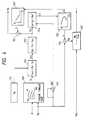
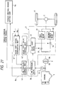
- FIG. 1 is a systematic constructive view of a first embodiment of a drive shaft torque controlling apparatus for use in an automobile having a power transmission mechanism according to the present invention.
- a drive shaft torque controlling apparatus of the first embodiment comprises an engine 101, a multi-stepped automatic transmission (AT) 102, a propelling shaft 103, a differential apparatus 104, driving wheels 105, a hydraulic circuit 106 of the automatic transmission (AT) 102, an automatic transmission controlling unit (ATCU) 107 of the automatic transmission (AT) 102, an electronic controlling unit (ECU) 108 of the engine 101, an air cleaner 109, an air flow sensor 110, a throttle controlling means 111, an intake manifold 112 and injectors 113.
- AT automatic transmission controlling unit
- ECU electronic controlling unit
- a torque converter 114 and a gear train 115 are branched separately, and an output shaft speed sensor 117 of the automatic transmission (AT) 102 is provided on.
- the electronic controlling unit (ECU) 108 receives output signals of a crank angle sensor, the air flow sensor 110 and a throttle sensor 118 and executes the engine speed etc..
- the electronic controlling unit (ECU) 108 outputs a valve opening driving signal to the injector 113 and controls a fuel amount. Further, the electronic controlling unit (ECU) 108 outputs a valve opening driving signal to an idle speed controlling valve (ISC valve) 119 and controls a compensate air amount. Not shown in the figure is that the electronic controlling unit (ECU) 108 outputs an ignition signal to an ignition plug and controls an ignition time.
- ISC valve idle speed controlling valve
- the automatic transmission controlling unit (ATCU) 107 performs various executions from receiving input signals of the output shaft speed sensor 117 and an automatic transmission (AT) oil temperature sensor etc. and information relating to the engine speed and the throttle opening degree outputted from the electronic controlling unit (ECU) 108. Further, the automatic transmission controlling unit (ATCU) 107 outputs an opening valve driving signal etc. to a changeover electromagnetic valve 120 of the hydraulic circuit 106.
- Fig. 2 shows a schematic construction of the controlling portions of the above stated automatic transmission controlling unit (ATCU) 107 and electronic controlling unit (ECU) 108.
- the above controlling portions comprise a central processing unit (CPU) 133, an input/output interference circuit 138 and ROM 135 and RAM 136 by sandwiching at least one bus 134.
- Fig. 3 is an executing and assuming block diagram of an input/output rotation velocity ratio r and an input shaft torque (turbine torque) of the automatic transmission at a condition of during a non gear shift.
- the input/output rotation velocity ratio r in the present invention means a ratio between a rotation velocity of the input shaft side of the automatic transmission (AT) 102 and a rotation velocity of the output shaft side of the automatic transmission (AT) 102.
- a gear position signal (GP) is inputted and in a block 140 the input/output rotation velocity ratio r is determined.
- an output shaft speed (Vsp) of the automatic transmission (AT) 102 is inputted from the output shaft speed sensor 117.
- the automatic transmission (AT) 102 during the non gear shift is met completely with a predetermined gear.
- a block 144 the output shaft speed (Vsp) is multiplied by the input/output rotation velocity ratio r, an input shaft speed (turbine speed) Nt is determined accurately.
- Nt r x Vsp (formula 1)
- this turbine speed Nt is divided by the inputted engine speed Ne, and a slip ratio e in the torque converter 114 is determined.
- e Nt / Ne (formula 2)
- a pump capacity coefficient Cp characteristic (e - Cp characteristic) is determined from the pump capacity of the torque converter 114 which has been stored in advance.
- An input torque of the torque converter 114, namely a pump torque Tp is expressed by a formula 3.
- Tp ⁇ x Ne2 (formula 3)
- Ne2 is determined and in a block 146 the pump torque Tp is determined.
- a torque ratio t is determined from a torque ratio t characteristic (e - t characteristic) of the torque converter 114 which has been stored in advance.
- the turbine torque Tt is determined.
- Tt t x Tp (formula 4) According to the above, the input/output rotation velocity ratio r during the non gear shift and the turbine torque Tt are executed and assumed highly and accurately.
- Fig. 4 is an executing and assuming block diagram of the input/output rotation velocity ratio r , which is a transitional condition for transferring the meeting from the present met gear to a next gear, and the turbine torque Tt.
- a block 150 from the engine torque characteristic map which has been stored in advance, the engine torque Te is determined.
- the engine torque Te is determined by the input information of the throttle opening degree ⁇ and the engine speed Ne.
- the engine torque Te can be determined from the input information of the engine intake air amount Qa and the engine speed Ne or an injection pulse width Ti and the engine speed Ne. Such an example is omitted from this description.
- a block 151 the pump torque Tp value during the non gear shift, which is immediately before the gear shift determined by Fig. 3, is stored.
- a deviation between this pump torque Tp and the engine torque Te determined in the block 150 is calculated in a block 152.
- T ACC Te - Tp (formula 5)
- This deviation is an accessory torque T ACC to be loaded to the engine 101. This deviation is stored into a temporary storing apparatus. During the gear shift, this T ACC value is utilized for the execution.
- a deviation between the engine torque Te determined by the block 150 and T ACC value is determined and this deviation is made as the pump torque Tp' during the gear shift at this time point.
- Tp' Te - T ACC (formula 6)
- the pump capacity coefficient Cp is determined from Ne2 of the engine speed Ne calculated by the block 145 and the pump torque Tp' during the gear shift according to the calculation through the formula 3. From this e - Cp characteristic which has been stored in advance in the block 155, the slip ratio e is determined.
- a block 156 according to the reversed calculation through the formula 2, the product of the slip ratio e and the engine speed Ne is determined, whereby the turbine speed Nt is determined.
- the torque ratio t is determined.
- the turbine torque Tp during the gear shift is determined.
- Fig. 5 is an explanatory view showing the view for coping with such a condition.
- a limitation region of the slip ratio value e used for the execution is shown. Namely, commonly, the region in which the slip ratio e has a small value exists at only one condition, namely when the driver wants to start the automobile.
- the input/output rotation velocity ratio r and the turbine torque Tt during the gear shift can be determined.
- Fig. 6 is a block diagram showing an overall control of one embodiment of the drive shaft torque controlling apparatus according to the present invention.
- a block 160 is a torque converter characteristic utilizing and assuming unit, this unit includes the executing and the assuming block at the condition during the non gear shift which was explained in detail in Fig. 3.
- a block 161 which is surrounded by dot line is an engine torque map utilizing and assuming unit, this unit includes the executing and the assuming block at the condition during the gear shift which was explained in detail in Fig. 4.
- the judgement whether or not being in a gear shift is carried out in the gear shift time detecting unit in a block 162. This judgement is carried out by a signal of CUR GP (gear position at the current time) and a signal of NXT GP (gear position which is wanted to do the gear shift or gear position at the next time).
- this logic judges, when both signals are the same, that the gear shift has finished, and when both signals are not the same, it judges that the gear shift is going on.
- the method for generating CUR GP signal and NXT GP signal used for the judgement is explained in Fig. 7 in latter.
- the block 162 in the first time judges a gear shift operation and it judges the gear shift starting, then the signal is sent to a block 161c.
- the accessory torque T ACC is stored using the formula 5.
- This accessory torque T ACC value is held until the next gear shift starting command is reached from the block 162 and it is utilized for the execution of the formula for the pump torque Tp' during the gear shift time which is carried out in a block 161d.
- the pump torque Tp' is determined.
- a block 163 is a changeover means for changing over the turbine torque Tt determined in the block 160 and the turbine torque Tt determined in the block 161.
- a block 164 is a changeover means for changing over the input/output rotation velocity ratio r determined in the block 160 and the input/output rotation velocity ratio r determined in the block 161.
- the changeover motion of the above both changeover means is carried out by the gear shift time signal of the block 162 and the signal from a lockup (L/U), coast and engine braking judging unit in the block 165.
- the lockup (L/U) indicates a condition in which the pump impeller and the turbine impeller of the torque converter 114 are connected mechanically by the hydraulic pressure.
- the coast and engine braking indicates a condition during the engine braking operation.
- the logic for changing over is as following.
- the block 161c is operated by L/U signal from the block 165, using the formula 5 the accessory torque T ACC is executed and stored.
- This accessory torque T ACC value is held or maintained until L/U signal stopping command is reached from the block 165.
- This accessory torque T ACC value is utilized for the execution of the pump torque Tp' in the block 165 and the execution of the turbine torque Tt, the input/output rotation velocity ratio r in the block 161b. Namely, in a case in which L/U signal is generated it is determined by utilizing the block 161.
- the torque converter 114 since the torque converter 114 becomes the driving condition at the reversed condition of the common condition, it can not utilize the above stated e - t characteristic and e - Cp characteristic as they are.
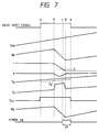
- Fig. 7 is one example of a time chart when the control of the embodiment is carried out.
- Fig. 7 shows a case of an up shift.
- a gear shift diagram (shift schedule) is described and stored by the output shaft speed Vsp, the engine speed Ne or the output shaft speed Vsp and the throttle opening degree ⁇ etc..
- the gear shift command signal is outputted (a point a in Fig. 7).
- time point a After time point a , it is determined by the procedure shown in Fig. 4, by the execution of the input/output rotation velocity ratio r , and the turbine torque Tt.
- the accessory torque T ACC is determined from the formula 5 and this accessory torque T ACC value is stored and held at a - e period, namely the gear shift period.
- the pump torque Tp' is determined at a predetermined executing cycle.
- the slip ratio e and the turbine speed Nt are determined.
- the stop of the gear shift command signal is exemplified using the following method.
- a predetermined slice level S/L is provided and when the input/output rotation velocity ratio r determined by the execution becomes less than S/L, a timer tm is settled to initialized only at ⁇ t time and to finish at a point e . This timer finishing point is made as the stopping point of the gear shift command signal.
- a method can be employed in which the timer is made to work at an optional settling time from the point a and to stop.
- the timer is made to work at an optional settling time from the point a and to stop.
- the detecting means such as the disc having the groove at the outer peripheral and the turbine sensor, and since it can assume the input shaft speed of the automatic transmission (AT) 102, namely the turbine speed and the input shaft torque of the automatic transmission (AT) 102, namely the turbine torque, without lowering the accuracy, the low cost and the light weight drive shaft torque controlling apparatus for use in the automobile can be obtained.
- an output of an engine 1 is torque-amplified by a torque converter 2 and given to a multi-stepped automatic transmission 3.
- the speed is converted in this multi-stepped automatic transmission 3 and the engine 1 drives tires 6 through a drive shaft 4 and a final gear 5.
- the torque converter 2 comprises a pump impeller 2a and a turbine impeller 2b.
- a crank angle sensor 16 for detecting the speed etc. of the engine 1 is provided on the engine 1.
- a throttle sensor 13 for detecting a valve opening degree (throttle opening degree) is provided on a throttle valve 13a for adjusting an air flow amount to be supplied to the engine 1. Further, a vehicle speed sensor 14 for detecting a speed (drive shaft speed) of the drive shaft 4 is provided on the drive shaft 4.
- a drive shaft torque controlling apparatus 15 in this second embodiment comprises an engine controlling unit 7, an automatic transmission controlling unit 8, a torque control period setting unit 9, a drive shaft torque calculating unit 10, a reference drive shaft torque setting unit 11 and a torque deviation executing unit 12.
- the engine controlling unit 7 controls the engine 1 and the automatic transmission controlling unit 8 controls the multi-stepped automatic transmission 3.
- the torque control period setting unit 9 sets a control period of the drive shaft torque during the gear shift.
- the drive shaft torque calculating unit 10 calculates a torque (drive shaft torque) of the drive shaft 4 according to the outputs from the crank angle sensor 16, the throttle sensor 13 and the vehicle speed sensor 14.
- the reference drive shaft torque setting unit 11 determines a reference drive shaft torque Ta during the torque control period, and a torque deviation executing unit 12 for obtaining a deviation d between a drive shaft torque Td obtained by the drive shaft torque calculating unit 10 and the reference drive shaft torque Ta.
- the engine controlling unit 7 controls the engine 1 so as to decrease the deviation d obtained by the torque deviation executing unit 12.
- the deviation d is decreased to become substantial zero (including zero).
- the engine controlling unit 7, to be concretely, controls an ignition plug driving circuit (not shown) so as to change an ignition period so as to decrease the deviation d .
- Fig. 9 is a functional diagram of the drive shaft torque calculating unit 10.
- the drive shaft torque calculating unit 10 comprises an engine torque executing unit 21 for obtaining an engine torque Te from a throttle opening degree ⁇ and an engine speed Ne, an engine speed square processing unit 22 for obtaining a square value Ne2 of the engine speed Ne, a capacity coefficient executing unit 23 for obtaining an input pump capacity coefficient Cp by dividing the engine torque Te by the square value Ne2 of the engine speed Ne, a slip ratio executing unit 24 for obtaining a slip ratio e of the torque converter 2 from the input pump capacity coefficient Cp.
- the drive shaft torque calculating unit 10 comprises further a turbine speed executing unit 25 for obtaining a turbine speed Nt by multiplying this slip ratio e by the engine speed Ne, an input/output rotation velocity ratio executing unit 26 for obtaining an input/output rotation velocity ratio r of the multi-stepped automatic transmission 3 by dividing the turbine speed Nt by the drive shaft speed Nd, a torque ratio executing unit 27 for obtaining a torque ratio t of the torque converter 2 from the slip ratio e of the torque converter 2, a turbine torque executing unit 29 for obtaining a turbine torque Tt by multiplying the engine torque Te by the torque ratio t of the torque converter 2, and a drive shaft torque executing unit 29 for obtaining a drive shaft torque Td multiplying the turbine torque Tt by the input/output rotation velocity ratio r .
- the input/output rotation velocity ratio r indicates a ratio between a rotation velocity of an input shaft side of the automatic transmission 3 and a rotation velocity of an output shaft side of the automatic transmission 3.
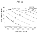
- an engine torque characteristic map showing a relationship between the engine speed Ne, the throttle opening degree ⁇ and the engine torque Te is provided.
- a pump capacity coefficient characteristic map showing the input pump capacity coefficient Cp and the slip ratio e is provided.
- a torque ratio characteristic map showing the torque ratio t and the slip ratio e is provided.
- the engine torque executing unit 21 using the engine torque characteristic map shown in Fig. 10, the engine torque Te corresponding to the engine speed Ne and the throttle opening degree ⁇ is obtained.
- the square value Ne2 of the engine speed Ne is obtained.
- the pump capacity coefficient executing unit 23 as shown in formula 9, by dividing the engine torque Te by the square value Ne2 of the engine speed, the input pump capacity coefficient Cp of the torque converter 2 is obtained.
- Cp Te / Ne2 (formula 9)
- Nt e x Ne (formula 10)
- the input/output rotation velocity ratio executing unit 26 by dividing the turbine speed Nt by the drive shaft speed Nd, namely dividing the input shaft speed Nt of the multi-stepped automatic transmission 3 by the output shaft speed Nd, the input/output rotation velocity ratio r of the multi-stepped automatic transmission 3 is obtained.
- This timer is settled by anticipating the operation delay of a transmission hydraulic system, so that immediately before the actual operation of the gear shift clutch a time flag is reset so as to be finished.
- the turbine torque Tt, the input/output rotation velocity ratio of the automatic transmission 3 and the drive shaft torque Tt are calculated in the drive shaft torque calculating unit 10 immediately before the raise down point of the time flag, namely immediately before the actual operation of the gear shift clutch, as a turbine torque level P1, a gear shift ratio level Q1 and a drive shaft torque level R1. They are stored in a table of the torque control period setting unit 9 (step 2).
- the torque control period setting unit 9 predetermines a turbine torque level P2 which is a torque level value slightly larger than the turbine torque level P1 immediately before the actual motion of the gear shift clutch to start (step 3).
- control period setting unit 9 determines an input/output rotation velocity ratio level Q2 in which a level value is slightly larger than an input/output rotation velocity ratio level Q3 at the gear shift finishing (step 4).
- the gear shift clutch is engaged completely, and the input/output rotation velocity ratio is determined fixedly. Therefore, in a case that the input/output rotation velocity ratio is determined in advance at every gear shift step and a value thereof is stored in the table etc., by referring to this table the input/output rotation velocity ratio at the gear shift finishing can be obtained.
- the input/output rotation velocity ratio corresponding to this third gear becomes, by referring to the table, the input/output rotation velocity ratio level Q3 at the gear shift finishing.
- the gear shift starting indicates to a state in which the multi-stepped automatic transmission 3 starts to a mechanical motion.
- the gear shift finishing indicates a state in which the multi-stepped automatic transmission 3 finishes the mechanical motion.
- a state under the gear shift indicates a period between the gear shift starting and the gear shift finishing.
- step 5 beginning when the turbine torque level P2 is exceeded by the turbine torque Tt and ending when the gear shift level Q2 is reached by the input/output rotation velocity ratio r , the torque feedback control is carried out.
- a control period of this torque feedback control is managed through the torque control period setting unit 9.
- the deviation d is a torque deviation obtained between the current time drive shaft torque Td which is obtained from the drive shaft torque calculating unit 10 and the reference drive shaft torque Ta which is obtained from the reference drive shaft torque setting unit 11, and this deviation d is obtained in the torque deviation executing unit 12.
- the torque feedback control is carried out by controlling the engine 1 through the engine controlling unit 7 so as to decrease the above stated deviation d to substantially zero.
- the reference drive shaft torque pattern Ta which is determined by the reference drive shaft torque setting unit 11 is a linear pattern having a determined inclination at the drive shaft torque level R1 as the starting point. This inclination can utilize a pattern which is stored in advance in the reference drive shaft torque setting unit 11 every gear shift step.
- the reference drive shaft torque pattern Ta may be determined so as to connect linearly the drive shaft torque Td at the gear shift finishing time and the drive shaft torque Td immediately before the gear shift starting time.
- the engine torque Te is merely reduced, it cannot correspond to the instant fall-down of the drive shaft torque Td observed in the gear shift starting time.
- the change of the turbine torque Tt changes more abruptly than the change of the turbine speed Nt, as a result the mechanical change of the multi-stepped automatic transmission 3 can be detected easily. Accordingly, it can avoid the appearance of the gear shift jolt in which the torque control starting time is to late with respect to the gear shift starting time.
- the drive shaft torque Td is raised up abruptly because the acceleration pedal is stepped and when the gear shift starts it is fallen down at once, and further with the gear shift finishing the drive shaft torque Td overshoots and raises up again and settles thereafter.
- the above phenomenon is common motion of the drive shaft torque Td.
- the fallen down overshoot of the torque after the gear shift starting is called as “downward overshoot” and the overshoot of the torque after the gear shift finishing is called as “upward overshoot”.
- downward overshoot the overshoot of the torque after the gear shift finishing
- upward overshoot the overshoot of the torque after the gear shift finishing
- the "downward overshoot” is caused by the energy absorption for increasing the inertia moment of the gear shift mechanism. Since it is difficult to get rid of it, the raise-up of the torque occurring before the "downward overshoot" is suppressed by the feedback, whereby the torque fluctuation can be restrained by suppressing the downward overshoot part.
- the "upward overshoot" can be restrained by smoothing the raise-up of the torque, however, with respect to the gear shift feeling it is necessary to perform the moderate raise-up of the torque, whereby the torque fluctuation can be restrained by suppressing the upward overshoot part.
- the torque control period setting unit 9 determines the input/output rotation velocity ratio level Q2 having slightly smaller level value than the input/output rotation velocity ratio level Q3 at the gear shift finishing time (step 12).
- the torque control period setting unit 9 estimates the drive shaft torque Td in which the drive shaft torque Td settles after the gear shift finishing time and predetermines the drive shaft torque levels R2 and R3 which are sliced at a predetermined rate between the drive shaft torque level R5 and the drive shaft torque level R1.
- a drive shaft torque Td is obtained from the current time engine torque Te and the input/output rotation velocity ratio r at the gear shift finishing time.
- a step 14 so as to restrain the raise-up of the drive shaft torque Td before the "downward overshoot", during from when the drive shaft torque Td becomes the drive shaft torque level R2 to when the input/output rotation velocity ratio r becomes the input/output rotation velocity ratio level Q2, the torque feedback control can be carried out.
- the control period of the torque feedback control is managed by the torque control period setting period unit 9.
- the reference drive shaft torque pattern Ta1 having a predetermined inclination starting from the drive shaft torque level R2 is outputted.
- the deviation d between this reference drive shaft torque pattern Ta1 and the current time drive shaft torque Td is decreased to substantially zero, whereby the engine torque Te is controlled.
- the torque control period setting unit 9 estimates again the gear shift level R5 in which the drive shaft torque Td is settled and determines the gear shift torque having slightly smaller level value than the gear shift level R5 as the drive shaft torque level R4.
- step 15 the reasons, why in addition to step 13 again in step 15 the drive shaft torque Td is estimated when after the gear shift finishing time the drive shaft torque Td has settled, is, that by using the engine torque Te nearly to the engine torque Te when the drive shaft torque Td has settled, it is possible to obtain the drive shaft torque Td as exact as possible.
- a step 16 so as to restrain the "upward overshoot" of the drive shaft torque Td, when the drive shaft torque Td exceeds or equals the drive shaft torque level R3, the torque feedback control can be carried out.
- This control period of the torque feedback control is managed by the torque control period setting unit 9.
- the reference drive shaft torque pattern Ta2 having a predetermined inclination starting from the drive shaft torque level R3 is outputted, and the engine torque Te is controlled by decreasing the deviation d between this reference drive shaft torque pattern Ta2 and the current time drive shaft torque Td to substantially zero.
- the reference drive shaft torque Ta determines and since so as to decrease substantially zero the deviation d between the reference drive shaft torque Ta and the actual drive shaft torque Td the feedback control is carried out, the multi-stepped automatic transmission 3 and the hydraulic control mechanism etc. may change in the time lapse, accordingly regardless of the change in the time lapse, the gear shift jolt can be reduced effectively.
- the torque feedback control is carried out, it is unnecessary to provide the high cost sensor for obtaining the drive shaft torque Td by the execution, and since it changes only at the software aspect the controlling apparatus for the vehicle on the automatic transmission 3 is mounted, the reduction of the moderate gear shift jolt can be realized, the productivity can be heighten and also the reduction in the manufacturing cost can be attained.
- the turbine speed Nt is obtained through the execution, but in this third embodiment a turbine sensor 17 for detecting the turbine speed Nt is provided on the turbine impeller 2b of the torque converter 2. Using this turbine sensor 17 the turbine speed Nt is detected directly.
- the drive shaft torque calculating unit 10a since in the process for obtaining the torque ratio t of the torque converter 2, it is necessary to obtain the slip ratio e of the torque converter 2, the drive shaft torque calculating unit 10a has a rotation ratio executing unit 24a in which the rotation ratio e is obtained by dividing the turbine speed Nt detected through the turbine sensor 17 by the engine speed Ne.
- the precise turbine speed Nt can be utilized.
- Such a turbine speed Nt is more precisely than the turbine speed Nt obtained through the various executing processes.
- the drive shaft torque Td etc. can be obtained more precisely and the control accuracy can be improved.
- This fourth embodiment relates to an apparatus in which an electronic throttle valve 18 is provided and this electronic throttle valve 18 can be driven a main body of the throttle valve in response to the electric signal.
- the throttle valve 13a shown in the first embodiment is mechanically connected to the acceleration pedal and is operated only in response to the operation amount of the acceleration pedal, besides since the electronic throttle valve 18 shown in this fourth embodiment is operated by the electric signal, the electronic throttle valve 18 can operate independently with respect to the operation amount of the acceleration pedal.
- the throttle opening degree ⁇ can be changed in response to the deviation d between the reference drive shaft torque Ta and the actual drive shaft torque Td.
- the air system control is performed with slightly delayed response, but it can control the torque in a wide range, whereby it is possible to control any direction of the increasing torque or the decreasing torque.
- this fourth embodiment it can act effectively to the part which is necessary to increase the drive shaft torque Td, to put it concretely, in case of the up shift with the fallen down part (R2 time point in Fig. 13) of the torque, in other words it is called as the torque phase and in the case of the down shift with the "downward overshoot" part and further the torque fluctuation can be lessened.
- the throttle valve opening degree ⁇ may vary in response to the deviation d between the reference drive shaft torque Ta and the actual drive shaft torque Td.
- the ignition timing it is preferred to control the ignition timing. Accordingly, with respect to the part in which the actual drive shaft torque Td is larger than the reference drive shaft torque Ta it is necessary to reduce the drive shaft torque Td, e.g. by controlling the ignition timing.
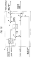
- the multi-stepped automatic transmission 3 is constituted to an automatic transmission main body and a hydraulic control mechanism.
- the transmission main body comprises a necessary number of pairs of gears 31 and 32, each of which is determined respectively to have a input/output rotation velocity ratio.
- Clutches 33 and 34 are provided on every gears 31 and 32.
- the hydraulic control mechanism comprises an oil pump 35, a line pressure adjusting valve 36 for adjusting the oil pressure from the oil pump 35, and a gear shift valve 37 for sending the adjusted pressure oil to one of the clutches 33 and 34.
- the automatic transmission controlling unit 8a comprises a gear shift signal generation unit 41 for preparing the throttle opening degree ⁇ and the drive shaft speed Nd (proportional to the vehicle speed Vsp), a gear shift valve controlling unit 42 for outputting the line changeover signal to the gear shift valve 37 in response to the gear shift signal, and a line pressure controlling unit 43 for outputting the pressure adjustment signal to the line pressure adjusting valve 36 in response to the gear shift signal and the torque control period signal.
- a line changeover signal is output to the gear shift valve 37, so as to meet the clutch of the gear shift step in response to the gear shift signal.
- the hydraulic circuit is changed over, whereby the oil from the oil pump 35 is supplied to the aimed clutch.
- the line pressure adjusting valve 36 adjusts the line pressure so as to obtain the meeting pressure in response to the aimed clutch.
- the line pressure controlling unit 43 carries out the line pressure control also during the gear shift, whereby the gear shift jolt can be more reduced.
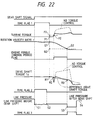
- Fig. 22 is a time chart of the up shift and shows in addition to the time chart shown in Fig. 13 the operation explanation waveform.
- the gear shift signal is changed over and at the same time the line pressure is varied to the line pressure S1 during the gear shift time which is calculated from the turbine torque Tt at a standard.
- the timer works at a determined time, and during this period it is controlled to the line pressure in response to the turbine torque Tt.
- the timer flag 2 At the finishing time point of the timer flag 2, it is held to the line pressure at that time (it does not relate to correspond to the turbine torque Tt). From the finishing time point of the engine torque control, as much as the time is determined by the time flag 3, further it varies to the line pressure S3. This line pressure S3 is smaller than at a predetermined rate against the line pressure S4 necessary for meeting the clutch after the gear shift.
- the time point for varying the line pressure S3 can determine not the finishing point of the engine torque control but can start to before the finishing point time, in such a case, once more threshold level is provided on the input/output rotation velocity ratio r and the line pressure S3 alteration starting point is determined. After the gear shift has finished, it controls the line pressure after the gear shift in response to a new input/output rotation velocity ratio.
- Fig. 23 is a time chart for the down shift and shows that in addition to the time chart shown in Fig. 15 the motion explanation waveform is shown.
- the gear shift signal is changed over and at the same time the line pressure is varied to the line pressure S1 which has a predetermined rate and is smaller than with the line pressure S0 necessary for meeting the clutch before the gear shift.
- the line pressure S1 which has a predetermined rate and is smaller than with the line pressure S0 necessary for meeting the clutch before the gear shift.
- the line pressure control is added to the system of the second embodiment, however, it can combine with the third embodiment or the fourth embodiment. In actually, in every system it is common to carry out the line pressure control.
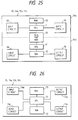
- the engine controlling unit 7 and the automatic transmission controlling unit 8 are provided on the vehicle as the in the distinct controlling apparatus and the independent form each other.
- a communication IC 56 is mounted on a microcomputer 50 having a function of the engine controlling unit 7 and a communication IC 66 is mounted on a microcomputer 60 having a function of the automatic transmission controlling unit 8, respectively, and it can realized by using LAN system for connecting the communication IC 56 and the communication IC 66 with the serial transmission passage.
- each microcomputer 50 and 60 in addition to the communication IC 56 and 66, CPU 51 and 61 for carrying out the various kinds of the executions and ROM 52 and 62 for storing the datum and programs so as to carry out the executions of CPU 51 and 61, RAM 53 and 63, input circuits 54 and 64, and output circuits 55 and 65 and so on are provided.
Landscapes
- Engineering & Computer Science (AREA)
- Chemical & Material Sciences (AREA)
- Combustion & Propulsion (AREA)
- Transportation (AREA)
- Mechanical Engineering (AREA)
- Automation & Control Theory (AREA)
- Control Of Transmission Device (AREA)
- Control Of Vehicle Engines Or Engines For Specific Uses (AREA)
Applications Claiming Priority (4)
| Application Number | Priority Date | Filing Date | Title |
|---|---|---|---|
| JP06884693A JP3246791B2 (ja) | 1993-03-26 | 1993-03-26 | 自動変速機の制御方法および制御装置、並びに自動車 |
| JP68846/93 | 1993-03-26 | ||
| JP10316693A JP3233494B2 (ja) | 1993-04-28 | 1993-04-28 | 駆動軸トルク制御装置 |
| JP103166/93 | 1993-04-28 |
Publications (3)
| Publication Number | Publication Date |
|---|---|
| EP0616919A2 true EP0616919A2 (fr) | 1994-09-28 |
| EP0616919A3 EP0616919A3 (fr) | 1994-12-28 |
| EP0616919B1 EP0616919B1 (fr) | 1997-09-17 |
Family
ID=26410034
Family Applications (1)
| Application Number | Title | Priority Date | Filing Date |
|---|---|---|---|
| EP94104879A Expired - Lifetime EP0616919B1 (fr) | 1993-03-26 | 1994-03-28 | Dispositif de réglage pour la force motrice dans les organes moteurs d'un véhicule |
Country Status (3)
| Country | Link |
|---|---|
| US (2) | US5608626A (fr) |
| EP (1) | EP0616919B1 (fr) |
| DE (1) | DE69405616T2 (fr) |
Cited By (9)
| Publication number | Priority date | Publication date | Assignee | Title |
|---|---|---|---|---|
| EP0683336A1 (fr) * | 1994-05-16 | 1995-11-22 | Eaton Corporation | Système/méthode pour la détermination du couple d'entraînement des accessoires d'un moteur et du taux de décélération dudit moteur |
| EP0683335A1 (fr) * | 1994-05-16 | 1995-11-22 | Eaton Corporation | Dispositif et méthode pour la détermination du couple volant de moteur |
| WO1997035739A1 (fr) * | 1996-03-26 | 1997-10-02 | Robert Bosch Gmbh | Procede et dispositif pour reguler le couple de rotation fourni par une unite d'entrainement |
| EP0751028A3 (fr) * | 1995-06-30 | 1998-04-01 | General Motors Corporation | Commande de couple de changement de vitesses |
| EP0670789B1 (fr) * | 1993-10-05 | 1998-06-10 | Robert Bosch Gmbh | Procede permettant de moduler le couple de sortie d'une boite de vitesses automatique |
| EP1148272A1 (fr) * | 2000-04-18 | 2001-10-24 | Ford Global Technologies, Inc. | Procédé d'estimation du couple d'un moteur à combustion interne |
| DE19710740B4 (de) * | 1996-03-15 | 2010-02-11 | Hitachi, Ltd. | Steuervorrichtung und Steuerverfahren zum Steuern von Kraftfahrzeug-Automatikgetrieben |
| DE19539954B4 (de) * | 1994-10-26 | 2010-06-02 | Hitachi, Ltd. | Steuervorrichtung für einen Antriebsstrang |
| CN114148343A (zh) * | 2021-12-23 | 2022-03-08 | 盛瑞传动股份有限公司 | 一种车辆控制方法、装置、电子设备及计算机存储介质 |
Families Citing this family (45)
| Publication number | Priority date | Publication date | Assignee | Title |
|---|---|---|---|---|
| KR960001444A (ko) * | 1994-06-06 | 1996-01-25 | 가나이 쯔도무 | 파워트레인의 제어장치 및 제어방법 |
| DE19526273C2 (de) * | 1995-07-19 | 1999-12-09 | Ford Werke Ag | Automatisch schaltbares Vorgelege-Wechselgetriebe, insbesondere für Kraftfahrzeuge |
| US5745103A (en) * | 1995-08-02 | 1998-04-28 | Microsoft Corporation | Real-time palette negotiations in multimedia presentations |
| JP3529004B2 (ja) * | 1996-05-21 | 2004-05-24 | スズキ株式会社 | 自動変速機の制御装置 |
| JPH10184871A (ja) * | 1996-12-25 | 1998-07-14 | Hitachi Ltd | 自動変速機の制御装置および制御方法 |
| US6438479B1 (en) * | 1997-12-29 | 2002-08-20 | Hitachi, Ltd. | Control apparatus for an automatic transmission of a vehicle and method |
| US6052637A (en) * | 1997-06-09 | 2000-04-18 | Eaton Corporation | Clutch adjustment determination |
| DE19726724A1 (de) * | 1997-06-24 | 1998-11-05 | Daimler Benz Ag | Verfahren zur Durchführung von Schaltvorgängen in einem automatisierten mechanischen Schaltgetriebe, insbesondere für Dieselmotoren |
| JP3754188B2 (ja) * | 1997-09-08 | 2006-03-08 | 日産自動車株式会社 | 車両の駆動力制御装置 |
| US6560549B2 (en) * | 1997-12-22 | 2003-05-06 | Caterpillar Inc | Method for determining the transmission output torque for an earth moving machine |
| DE19845167C2 (de) * | 1998-10-01 | 2000-11-16 | Zf Batavia Llc | Verfahren zur Erhöhung des Fahrkomforts von Kraftfahrzeugen |
| DE19906416A1 (de) * | 1999-02-16 | 2000-08-17 | Bayerische Motoren Werke Ag | Vorrichtung zur Drehmomentenadaption für Motormomentenmodell |
| US6434466B1 (en) * | 1999-05-06 | 2002-08-13 | Ford Global Technologies, Inc. | System and method for determining engine torque for controlling a powertrain |
| US6199004B1 (en) * | 1999-05-17 | 2001-03-06 | Ford Global Technologies, Inc. | Vehicle and engine control system |
| CA2327889C (fr) * | 1999-12-09 | 2004-04-20 | Honda Giken Kogyo Kabushiki Kaisha | Systeme de commande de transmissions automatiques de vehicules |
| JP3633421B2 (ja) * | 2000-02-25 | 2005-03-30 | トヨタ自動車株式会社 | 動力出力装置 |
| DE10010815A1 (de) * | 2000-03-08 | 2001-12-13 | Zahnradfabrik Friedrichshafen | Verfahren zum Steuern von Lastschaltungen eines Automatgetriebes |
| US6259986B1 (en) | 2000-03-10 | 2001-07-10 | Ford Global Technologies, Inc. | Method for controlling an internal combustion engine |
| US6226585B1 (en) * | 2000-04-18 | 2001-05-01 | Ford Global Technologies, Inc. | Torque estimation method for an internal combustion engine |
| JP3293613B2 (ja) * | 2000-06-23 | 2002-06-17 | 株式会社日立製作所 | 自動車用制御装置,自動車の制御方法,変速機 |
| DE10032920A1 (de) * | 2000-07-06 | 2002-01-17 | Bosch Gmbh Robert | Verfahren zum Betreiben eines Antriebsstrangs eines Kraftfahrzeugs und Steuerungssystems zur Durchführung des Verfahrens |
| US6360156B1 (en) * | 2000-11-01 | 2002-03-19 | General Motors Corporation | Method and system of determining an acceptable torque level to be applied to at least one clutch pack of an automobile |
| US7266379B2 (en) * | 2001-05-30 | 2007-09-04 | Palm, Inc. | Resource location through location history |
| DE10146742A1 (de) * | 2001-09-22 | 2003-08-21 | Voith Turbo Kg | Verfahren zur Steuerung und/oder Regelung des Schleppmomentes in einem Antriebsstrang und Steuer- und Regelsystem |
| DE10210343A1 (de) * | 2002-03-08 | 2003-09-25 | Zahnradfabrik Friedrichshafen | Verfahren zur Anpassung eines Antriebsmotors an einen hydrodynamischen Drehmomentwandler für ein Kraftfahrzeug |
| KR100527498B1 (ko) * | 2003-10-30 | 2005-11-09 | 현대자동차주식회사 | 자동 변속기에서 업 시프트 시 초기 유압 학습장치 및 그방법 |
| US7351183B2 (en) * | 2004-12-16 | 2008-04-01 | Ford Global Technologies, Llc | Ratio shift control for a multiple ratio automatic transmission |
| JP4919962B2 (ja) * | 2005-09-14 | 2012-04-18 | 日立オートモティブシステムズ株式会社 | 走行制御装置及び走行制御方法 |
| US9288751B2 (en) * | 2007-08-29 | 2016-03-15 | Qualcomm Incorporated | Use of position data to select wireless access point |
| RU2479453C2 (ru) * | 2008-07-17 | 2013-04-20 | Чжаохуань ХУАН | Автоматическая ступенчатая коробка передач транспортного средства |
| US9352749B2 (en) * | 2008-09-23 | 2016-05-31 | GM Global Technology Operations LLC | Torque sensor based vehicle direction determination |
| US8108096B2 (en) * | 2009-02-27 | 2012-01-31 | GM Global Technology Operations LLC | Diagnostic systems and methods for a torque sensor |
| US8342998B2 (en) * | 2009-04-09 | 2013-01-01 | Ford Global Technologies, Llc | Friction element load sensing in an automatic transmission |
| US8255130B2 (en) * | 2009-04-09 | 2012-08-28 | Ford Global Technologies, Llc | Closed-loop torque phase control for shifting automatic transmission gear ratios based on friction element load sensing |
| US8417411B2 (en) * | 2009-04-22 | 2013-04-09 | GM Global Technology Operations LLC | Torque sensor performance diagnostic systems and methods |
| JP5645414B2 (ja) * | 2010-02-03 | 2014-12-24 | 本田技研工業株式会社 | クラッチ制御装置 |
| US8392084B2 (en) | 2010-09-03 | 2013-03-05 | Honda Motor Co., Ltd | Increasing all-wheel drive system calibration efficiency through hardware-in-the-loop simulation techniques |
| US8744705B2 (en) * | 2012-03-15 | 2014-06-03 | GM Global Technology Operations LLC | System and method for determining clutch gains in a transmission during a power downshift |
| US9240700B2 (en) | 2012-09-07 | 2016-01-19 | Apple Inc. | Cascading power for accessories |
| US8788166B1 (en) | 2013-02-28 | 2014-07-22 | Ford Global Technologies, Llc | Downshift controls using measured output torque |
| EP2843388B1 (fr) | 2013-07-25 | 2016-05-25 | Parker Hannifin Corporation | Détection d'arbre d'entraînement pour la détection de pompe ou moteur |
| US9404571B2 (en) | 2014-06-04 | 2016-08-02 | Ford Global Technologies, Llc | Controlling an automatic transmission |
| JP6190985B2 (ja) * | 2015-02-17 | 2017-08-30 | 本田技研工業株式会社 | 駆動力配分装置の油圧制御装置 |
| US20180274463A1 (en) * | 2017-03-21 | 2018-09-27 | Cummins Inc. | Fast torque control with electric accessories |
| EP3724516B1 (fr) | 2017-12-14 | 2026-04-22 | Cummins, Inc. | Système de serrage |
Family Cites Families (26)
| Publication number | Priority date | Publication date | Assignee | Title |
|---|---|---|---|---|
| JPS4818976B1 (fr) * | 1969-10-13 | 1973-06-09 | ||
| US4018316A (en) * | 1974-03-07 | 1977-04-19 | General Motors Corporation | Engine and transmission power train |
| EP0128471B1 (fr) * | 1983-06-01 | 1988-04-20 | Mazda Motor Corporation | Dispositif de commande d'une transmission automatique d'un véhicule |
| JPS60131326A (ja) * | 1983-12-21 | 1985-07-13 | Nissan Motor Co Ltd | 自動変速機の変速シヨツク軽減装置 |
| JP2767793B2 (ja) * | 1987-04-20 | 1998-06-18 | 三菱自動車工業株式会社 | 自動変速装置の入力パワーオンオフ判定方法 |
| US4922424A (en) * | 1987-04-20 | 1990-05-01 | Mitsubishi Jidosha Kogyo Kabushiki Kaisha | Control method for a driving system provided in a vehicle |
| JPS644544A (en) * | 1987-06-26 | 1989-01-09 | Aisin Aw Co | Speed change control device for automobile |
| US4889014A (en) * | 1987-12-29 | 1989-12-26 | Honda Giken Kogyo Kabushiki Kaisha | System for controlling an internal combustion engine for motor vehicles equipped with an automatic transmission |
| JPS63254256A (ja) * | 1988-03-14 | 1988-10-20 | Nissan Motor Co Ltd | 自動変速機塔載車の変速ショック軽減装置 |
| US5021956A (en) * | 1988-04-25 | 1991-06-04 | Mazda Motor Corporation | Control systems for vehicle engines coupled with automatic transmissions |
| JPH0615308B2 (ja) * | 1988-07-04 | 1994-03-02 | 日産自動車株式会社 | パワートレーンの総合制御装置 |
| DE3825749A1 (de) * | 1988-07-29 | 1990-03-08 | Daimler Benz Ag | Verfahren zur adaptiven steuerung einer brennkraftmaschine und/oder einer anderen antriebskomponente eines kraftfahrzeuges |
| JP2559490B2 (ja) * | 1989-06-13 | 1996-12-04 | 日産自動車株式会社 | 車両の走行制御装置 |
| JP2875316B2 (ja) * | 1989-12-29 | 1999-03-31 | アイシン・エィ・ダブリュ株式会社 | 車両用無段変速機の制御装置 |
| JP2940042B2 (ja) * | 1990-01-23 | 1999-08-25 | 日産自動車株式会社 | 車両の制御戦略装置 |
| JP2827396B2 (ja) * | 1990-02-16 | 1998-11-25 | トヨタ自動車株式会社 | 車両用自動変速機 |
| JP2517171B2 (ja) * | 1990-11-19 | 1996-07-24 | 日産自動車株式会社 | エンジンと自動変速機の総合制御装置 |
| JP2623965B2 (ja) * | 1990-11-21 | 1997-06-25 | 日産自動車株式会社 | 自動変速機の変速制御装置 |
| JP2917179B2 (ja) * | 1991-01-09 | 1999-07-12 | 株式会社ユニシアジェックス | 自動変速機の出力軸トルク設定装置及び出力軸トルク制御装置 |
| KR950002561B1 (ko) * | 1991-02-13 | 1995-03-23 | 미쯔비시 지도샤 고교 가부시끼가이샤 | 자동 변속기의 변속 제어장치 |
| JP2868641B2 (ja) * | 1991-03-27 | 1999-03-10 | マツダ株式会社 | 自動変速機の変速制御装置 |
| US5101688A (en) * | 1991-06-03 | 1992-04-07 | Ford New Holland, Inc. | Driveline engagement/disengagement |
| DE59106776D1 (de) * | 1991-08-30 | 1995-11-30 | Siemens Ag | Steuerung für einen Kraftfahrzeugantrieb mit einem automatischen Getriebe. |
| US5212998A (en) * | 1991-12-02 | 1993-05-25 | Deere & Company | Transmission control system with load compensated shift modulation |
| KR100298250B1 (ko) * | 1992-09-16 | 2001-10-24 | 가나이 쓰도무 | 차량용구동력제어장치 |
| AU2001214602A1 (en) * | 2000-05-30 | 2001-12-11 | The Procter And Gamble Company | Hair conditioning composition comprising silicones and frizz control agents |
-
1994
- 1994-03-25 US US08/217,861 patent/US5608626A/en not_active Expired - Fee Related
- 1994-03-28 DE DE69405616T patent/DE69405616T2/de not_active Expired - Fee Related
- 1994-03-28 EP EP94104879A patent/EP0616919B1/fr not_active Expired - Lifetime
-
1996
- 1996-11-20 US US08/751,439 patent/US5938712A/en not_active Expired - Fee Related
Cited By (13)
| Publication number | Priority date | Publication date | Assignee | Title |
|---|---|---|---|---|
| EP0670789B1 (fr) * | 1993-10-05 | 1998-06-10 | Robert Bosch Gmbh | Procede permettant de moduler le couple de sortie d'une boite de vitesses automatique |
| US5582069A (en) * | 1994-05-16 | 1996-12-10 | Eaton Corporation | Engine accessory torque and engine deceleration rate determination method/system |
| US5509867A (en) * | 1994-05-16 | 1996-04-23 | Eaton Corporation | Engine flywheel torque determination method/system |
| EP0683336A1 (fr) * | 1994-05-16 | 1995-11-22 | Eaton Corporation | Système/méthode pour la détermination du couple d'entraînement des accessoires d'un moteur et du taux de décélération dudit moteur |
| EP0683335A1 (fr) * | 1994-05-16 | 1995-11-22 | Eaton Corporation | Dispositif et méthode pour la détermination du couple volant de moteur |
| DE19539954B4 (de) * | 1994-10-26 | 2010-06-02 | Hitachi, Ltd. | Steuervorrichtung für einen Antriebsstrang |
| EP0751028A3 (fr) * | 1995-06-30 | 1998-04-01 | General Motors Corporation | Commande de couple de changement de vitesses |
| DE19710740B4 (de) * | 1996-03-15 | 2010-02-11 | Hitachi, Ltd. | Steuervorrichtung und Steuerverfahren zum Steuern von Kraftfahrzeug-Automatikgetrieben |
| WO1997035739A1 (fr) * | 1996-03-26 | 1997-10-02 | Robert Bosch Gmbh | Procede et dispositif pour reguler le couple de rotation fourni par une unite d'entrainement |
| US6064934A (en) * | 1996-03-26 | 2000-05-16 | Robert Bosch Gmbh | Process and device for regulating the torque derived from a drive unit |
| EP1148272A1 (fr) * | 2000-04-18 | 2001-10-24 | Ford Global Technologies, Inc. | Procédé d'estimation du couple d'un moteur à combustion interne |
| US6379283B1 (en) | 2000-04-18 | 2002-04-30 | Ford Global Technologies, Inc. | Torque estimation method for an internal combustion engine |
| CN114148343A (zh) * | 2021-12-23 | 2022-03-08 | 盛瑞传动股份有限公司 | 一种车辆控制方法、装置、电子设备及计算机存储介质 |
Also Published As
| Publication number | Publication date |
|---|---|
| EP0616919A3 (fr) | 1994-12-28 |
| US5938712A (en) | 1999-08-17 |
| DE69405616D1 (de) | 1997-10-23 |
| EP0616919B1 (fr) | 1997-09-17 |
| DE69405616T2 (de) | 1998-01-29 |
| US5608626A (en) | 1997-03-04 |
Similar Documents
| Publication | Publication Date | Title |
|---|---|---|
| EP0616919B1 (fr) | Dispositif de réglage pour la force motrice dans les organes moteurs d'un véhicule | |
| JP2515457B2 (ja) | 内燃機関のトルク制御方法 | |
| EP0410223B1 (fr) | Système de commande électronique pour l'accouplement de pontage d'un convertisseur de couple | |
| KR100660244B1 (ko) | 자동차의 드라이브 트레인용 제어 시스템 | |
| US4691285A (en) | Method and apparatus for alleviating transmission shift shocks | |
| CN100497058C (zh) | 机械式变速箱的变速控制方法及装置 | |
| US7393305B2 (en) | Controller for automatic transmission | |
| JPH06174067A (ja) | 自動車用の自動変速機と動力伝達系統装置 | |
| US5613920A (en) | Torque feedback shift control device and method | |
| JPH04244665A (ja) | 自動変速機のシフト制御方法及び制御装置 | |
| EP2105634B1 (fr) | Contrôleur de transmission automatique, procédé de contrôle de transmission automatique | |
| US6067494A (en) | Control apparatus and control method for automatic transmission of vehicle | |
| US5678674A (en) | Control device for regulating the engaging process of a separating clutch for motor vehicles | |
| JPH07109247B2 (ja) | 変速器アップシフト制御方法及び装置 | |
| US5562567A (en) | Shift torque management | |
| JPH0835437A (ja) | パワートレイン制御装置および制御方法 | |
| JP3193244B2 (ja) | 車両の駆動トルク制御装置 | |
| US6052640A (en) | Automotive torque converter slip estimation | |
| JP2003090423A (ja) | 流体式トルクコンバータのタービントルク算出装置、車両の駆動トルク制御装置 | |
| JPH10184871A (ja) | 自動変速機の制御装置および制御方法 | |
| JP3233494B2 (ja) | 駆動軸トルク制御装置 | |
| JP3623077B2 (ja) | 自動変速機の変速過渡制御装置 | |
| JPS60222645A (ja) | 自動変速機の変速シヨツク軽減装置 | |
| JPH092106A (ja) | パワ−トレイン制御装置およびそのシステム | |
| JPH08277932A (ja) | ロックアップクラッチ制御装置および方法 |
Legal Events
| Date | Code | Title | Description |
|---|---|---|---|
| PUAI | Public reference made under article 153(3) epc to a published international application that has entered the european phase |
Free format text: ORIGINAL CODE: 0009012 |
|
| AK | Designated contracting states |
Kind code of ref document: A2 Designated state(s): DE FR GB |
|
| PUAL | Search report despatched |
Free format text: ORIGINAL CODE: 0009013 |
|
| 17P | Request for examination filed |
Effective date: 19941011 |
|
| AK | Designated contracting states |
Kind code of ref document: A3 Designated state(s): DE FR GB |
|
| 17Q | First examination report despatched |
Effective date: 19951123 |
|
| GRAG | Despatch of communication of intention to grant |
Free format text: ORIGINAL CODE: EPIDOS AGRA |
|
| GRAH | Despatch of communication of intention to grant a patent |
Free format text: ORIGINAL CODE: EPIDOS IGRA |
|
| GRAH | Despatch of communication of intention to grant a patent |
Free format text: ORIGINAL CODE: EPIDOS IGRA |
|
| GRAA | (expected) grant |
Free format text: ORIGINAL CODE: 0009210 |
|
| RAP1 | Party data changed (applicant data changed or rights of an application transferred) |
Owner name: HITACHI CAR ENGINEERING CO., LTD. Owner name: HITACHI, LTD. |
|
| AK | Designated contracting states |
Kind code of ref document: B1 Designated state(s): DE FR GB |
|
| REF | Corresponds to: |
Ref document number: 69405616 Country of ref document: DE Date of ref document: 19971023 |
|
| ET | Fr: translation filed | ||
| PLBE | No opposition filed within time limit |
Free format text: ORIGINAL CODE: 0009261 |
|
| STAA | Information on the status of an ep patent application or granted ep patent |
Free format text: STATUS: NO OPPOSITION FILED WITHIN TIME LIMIT |
|
| 26N | No opposition filed | ||
| REG | Reference to a national code |
Ref country code: GB Ref legal event code: IF02 |
|
| PGFP | Annual fee paid to national office [announced via postgrant information from national office to epo] |
Ref country code: GB Payment date: 20030224 Year of fee payment: 10 |
|
| PG25 | Lapsed in a contracting state [announced via postgrant information from national office to epo] |
Ref country code: GB Free format text: LAPSE BECAUSE OF NON-PAYMENT OF DUE FEES Effective date: 20040328 |
|
| GBPC | Gb: european patent ceased through non-payment of renewal fee |
Effective date: 20040328 |
|
| PGFP | Annual fee paid to national office [announced via postgrant information from national office to epo] |
Ref country code: FR Payment date: 20080225 Year of fee payment: 15 Ref country code: DE Payment date: 20080307 Year of fee payment: 15 |
|
| REG | Reference to a national code |
Ref country code: FR Ref legal event code: ST Effective date: 20091130 |
|
| PG25 | Lapsed in a contracting state [announced via postgrant information from national office to epo] |
Ref country code: DE Free format text: LAPSE BECAUSE OF NON-PAYMENT OF DUE FEES Effective date: 20091001 |
|
| PG25 | Lapsed in a contracting state [announced via postgrant information from national office to epo] |
Ref country code: FR Free format text: LAPSE BECAUSE OF NON-PAYMENT OF DUE FEES Effective date: 20091123 |