EP0619128A1 - Systeme d'affichage pour ilot de machines a sous - Google Patents
Systeme d'affichage pour ilot de machines a sous Download PDFInfo
- Publication number
- EP0619128A1 EP0619128A1 EP93900438A EP93900438A EP0619128A1 EP 0619128 A1 EP0619128 A1 EP 0619128A1 EP 93900438 A EP93900438 A EP 93900438A EP 93900438 A EP93900438 A EP 93900438A EP 0619128 A1 EP0619128 A1 EP 0619128A1
- Authority
- EP
- European Patent Office
- Prior art keywords
- display
- game machine
- game
- displaying
- event
- Prior art date
- Legal status (The legal status is an assumption and is not a legal conclusion. Google has not performed a legal analysis and makes no representation as to the accuracy of the status listed.)
- Withdrawn
Links
Images





Classifications
-
- A—HUMAN NECESSITIES
- A63—SPORTS; GAMES; AMUSEMENTS
- A63F—CARD, BOARD, OR ROULETTE GAMES; INDOOR GAMES USING SMALL MOVING PLAYING BODIES; VIDEO GAMES; GAMES NOT OTHERWISE PROVIDED FOR
- A63F5/00—Roulette games
- A63F5/04—Disc roulettes; Dial roulettes; Teetotums; Dice-tops
-
- G—PHYSICS
- G07—CHECKING-DEVICES
- G07F—COIN-FREED OR LIKE APPARATUS
- G07F17/00—Coin-freed apparatus for hiring articles; Coin-freed facilities or services
- G07F17/32—Coin-freed apparatus for hiring articles; Coin-freed facilities or services for games, toys, sports, or amusements
-
- G—PHYSICS
- G07—CHECKING-DEVICES
- G07F—COIN-FREED OR LIKE APPARATUS
- G07F17/00—Coin-freed apparatus for hiring articles; Coin-freed facilities or services
- G07F17/32—Coin-freed apparatus for hiring articles; Coin-freed facilities or services for games, toys, sports, or amusements
- G07F17/3202—Hardware aspects of a gaming system, e.g. components, construction, architecture thereof
- G07F17/3204—Player-machine interfaces
- G07F17/3211—Display means
-
- G—PHYSICS
- G07—CHECKING-DEVICES
- G07F—COIN-FREED OR LIKE APPARATUS
- G07F17/00—Coin-freed apparatus for hiring articles; Coin-freed facilities or services
- G07F17/32—Coin-freed apparatus for hiring articles; Coin-freed facilities or services for games, toys, sports, or amusements
- G07F17/3225—Data transfer within a gaming system, e.g. data sent between gaming machines and users
- G07F17/3232—Data transfer within a gaming system, e.g. data sent between gaming machines and users wherein the operator is informed
- G07F17/3234—Data transfer within a gaming system, e.g. data sent between gaming machines and users wherein the operator is informed about the performance of a gaming system, e.g. revenue, diagnosis of the gaming system
Definitions
- This invention relates to a display system for making an effective appeal with respect to a game machine where trouble or the like occurs or in the event of a winning condition of a game machine where a player wins game plays at a game machine island (dome) having a plurality of game machines such as slot machines.
- problems may occur at the machines, or a player may perform an illegal or cheating act. If a player meets a given condition while playing at a game machine, game play media such as medals are paid out to the player for the winning game plays from the game machine. If the player wins game plays repeatedly at the game machine, the game machine may be locked onto a win, namely, placed in a closed condition. In such a case, the player needs to call personnel in the game house so that they can take appropriate action.
- the game machine uses display means installed on the game machine to make representation such as displaying graphics representing the winning game play, blinking flash lamps, and producing sound through a loudspeaker celebrating the winning game play, applauding the player, and congratulating the player on his or her luck.
- the successful player would want to feel a sense of his or her own superiority over other players.
- unsuccessful players raise the sense of expectation of their own success from the success of another person.
- the players in such a mental state will be intent on playing games; this effect is favorable to game house managers for effective use of game machines.
- a system for displaying the occurrence of an event at a game machine island having at least one game machine row comprising a plurality of game machines placed side by side comprising: a dome display having a display area, provided along the game machine row of the game machine island for displaying in the display area; and a display controller for controlling the operation of the dome display, the dome display comprising a plurality of display units for displaying in a specified mode and drive circuits for driving the display units, the display units being disposed in the display area, the display controller comprising: event occurrence information read means, when a signal indicating that any game machine in the game machine row is in a predetermined specific condition is input, for reading information indicating the physical location of the game machine; means for distributing the display units into those being positioned to the left, when facing the game machine row and those positioned to the right, with the position corresponding to the position indicated by the information as reference; and means for controlling so as to cause the display units
- Each of the display units can have at least one light emitting element, and the control means can change the light and shade of the light emitting elements of the display units in the order in which the display units are arranged so as to create a display mode representing the directionality.
- Each of the display units can have a plurality of light emitting elements arranged along the game machine row, and the control means can change the light and shade of the light emitting elements in the order in which they are arranged in each display unit so that a display mode representing directionality is created.
- the event occurrence information read means can further include a function of reading information indicating contents of a specific condition occurring at any game machine.
- the display control means can further comprise means for storing information for specifying a predetermined display mode in response to the information indicating the specific condition contents.
- the control means can read the stored information for specifying a display mode in response to the read information indicating the specific condition contents for causing the display means to display in the display mode.
- the event occurrence information read means can have at least either of a function of reading information indicating occurrence of an event at any game machine and a function of reading information indicating that any game machine is placed in a winning condition.
- Each of the display units can have a light emitting element and a graphics pattern display section for displaying a graphics pattern lit by the light emitting element.
- the graphics pattern display section can have a graphics pattern showing directionality from left to right and a graphics pattern showing directionality from right to left and selectively lights either of them in response to an instruction from the display control means.
- Each of the display units can have a panel display and each of the drive circuits can have a memory which stores image data for generating graphics displayed on the screen of the panel display.
- the drive circuit can have means for moving image data in a direction conforming to the directionality on the screen of the panel display.
- the memory stores image data representing graphics patterns corresponding to the two types of directionality.
- a system for displaying occurrence of an event at a game machine island having at least one game machine row comprising a plurality of game machines placed side by side comprising: a display having a display area in each game machine for displaying in the display area; and a display controller for controlling the operation of the display, the display comprising a plurality of display units for displaying in a specified mode and drive circuits for driving the display units, the display units being disposed in the display area, the display controller comprising: event occurrence information read means, when a signal indicating that any game machine in the game machine row is in a predetermined specific condition is input, for reading information indicating the position of the game machine; means for distributing the display units into those positioned to the left, when facing the game machine row and those positioned to the right, with the position corresponding to the position indicated by the information as reference; and means for controlling so as to cause the display units positioned to the left to display in a display mode representing directionality from the left end to the
- the display system comprising: a display controller, upon occurrence of some event for any game machine in the game machine row, for controlling so as to change the display mode of the displays of the game machines belonging to the same game machine row accordingly, the display controller comprising: event occurrence information read means for reading event occurrence information indicating occurrence of an event for any game machine in the game machine row; means for distributing the game machines into those positioned to the left, when facing the game machine row, and those positioned to the right, with the position of the game machine indicated by the event occurrence information as reference; and control means for instructing the displays of the game machines positioned to the left to display in a display mode representing directionality from the left end to the reference position and the displays of the game machines positioned to the right to display in a display
- the display system comprising: a dome display having a display area provided along the game machine row of the game machine island for displaying in the display area; and a display controller, upon occurrence of some event for any game machine in the game machine row, for controlling so as to change the display modes of the displays of the game machines and the dome display belonging to the same game machine row accordingly, the dome display comprising a plurality of display units for displaying in a specified mode and drive circuits for driving the display units, the display units being disposed in the display area, the display controller comprising: event occurrence information read means for reading event occurrence information indicating occurrence of an event for any game machine in the game machine row; means for distributing the game machines and display units into those positioned to the left, when facing the game machine row, and those positioned to the right, with
- the display control means controls the display units disposed throughout the entire area in the longitudinal direction where the game machines are located so that graphics patterns or light and shade displayed on the display means are moved toward the game machine.
- the liquid crystal screens display an appeal over a wide range of the entire game machine island to indicate the occurrence of a problem or the like at the game machine, and moreover display means dedicated to calling personnel in the game house need not be provided.
- the display system of the invention can contribute to increased demand for game systems and development of the industry.
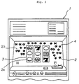
- a display system is applied to a game machine island 10 having at least one row of game machines 1 placed side by side each comprising a display 2 within which an area for playing games is displayed, as shown in Figure 4.
- the system is for indicating the occurrence of events at the game machine island 10.
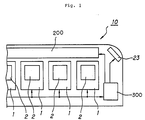
- the display system comprises a dome display 200 for displaying in a specified mode in a display area 22 disposed along a game machine row on the top of a game machine island 10 and a display controller 300, when some event occurs for any game machine 1 in the game machine row, for controlling accordingly so as to change the display modes of the displays 2 of the game machines 1 and the dome display 200 belonging to the same game machine row, as shown in Figure 1.
- the dome display 200 has a plurality of display units 210 for displaying in the specified mode and a plurality of display drive circuits 250 for driving these display units 210, as shown in Figure 6.
- the display units 210 are arranged in the display area 22 shown in Figure 4 in the longitudinal direction of the game machine island 10, namely, along the game machine row. In the embodiment, they are provided in three colors of red, blue, and green.
- light emitting elements or color filters for emitting light of the colors are disposed, for example, as a striped structure.
- the colors are not limited to those mentioned. It is also possible to use only one color.
- the display unit 210 has a plurality of light emitting elements 211 and a circuit 210 for driving the light emitting elements so as to produce light and shade.
- the size of the display unit 210 can be determined so as to conform to the width of the game machine, for example.
- the light emitting elements can be made of fluorescent lamps, tungsten lamps, light emitting diodes, etc., for example.
- the light emitting face form, the number, and arrangement of the light emitting elements 211 are determined so that a light band extending in the width direction of the display area 22 can be generated.
- the light emitting element 211 may be a set of light emitting substances.
- color filters may be used.
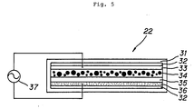
- the light emitting element 211 can also be made of an organic dispersion electro-luminescence lamp which comprises moisture absorption layers 32, a transparent electrode layer 33, a light emitting layer 34, an insulation layer 35, and a back plate layer 36 laminated on each other within a moisture proof film 31 forming a surface layer, as shown in Figure 5.
- This type of element uses light emitted by applying an alternating electric field to phosphor contained in the light emitting layer 34.
- the light emitting element 211 has features of thin form, light weight, shock resistance, uniform face light emission, low power consumption, small heating value, and high flexibility in form.
- the display drive circuit 250 comprises drive circuits 251 each provided for each light emitting element 211 for turning on and blinking their corresponding light emitting elements, a shift register 252 for turning on the drive circuits 251 in cyclic sequence, a selector 253 for selecting the forward or reverse order for the cycle order of turning on the drive circuits 251, a clock circuit 254 for supplying clock pulses to the shift register, and a trigger circuit 255 such as a one-shot multivibrator for supplying trigger pulses to the shift register 252, for example, as shown in Figure 7.
- the shift register 252 consists of a serial in-parallel out shift register. Each time a pulse is input from the trigger circuit 255, the shift register 252 shifts the pulse in order, thereby moving the on state of each parallel-out pin in order. An output at the last stage of the shift register 252 is connected to a serial input for causing the shift operation to cycle. Therefore, once a trigger pulse is input, the shift operation is repeated until reset.
- the drive circuits 251 are also turned on cyclically and blinks of the light emitting elements 211 move in the forward or reverse order in response to the on cycle.
- the order from left to right as viewed when facing the game machine island 10 is assumed to be the forward order and from right to left is the reverse order.
- the clock circuit 254 comprises a variable frequency divider and outputs a clock pulse having a period responsive to an instruction from the display controller 300. For example, to inform personnel in the game house of the occurrence of an emergency, a change can be made so as to accelerate the movement of light and shade, etc.
- the display controller 300 has the main functions of event occurrence information read means 301 for reading event occurrence information indicating the occurrence of an event for any game machine in the game machine row, distribution means 302 for distributing the game machines 1 and the display units 210 into those positioned to the left, when facing the game machine row, and those positioned to the right, with the position of the game machine 1 indicated by the event occurrence information as reference, and control means 303 for instructing the game machines 1 and the display units 210 positioned to the left to display in a display mode representing directionality from the left end to the reference position and the game machines 1 positioned to the right to display in a display mode representing directionality from the right end to the reference position.
- the event occurrence information read means 301 further includes a function of reading information indicating the contents of a specific condition occurring at any game machine 1.
- the events read by the event occurrence information read means 301 include the following events: Some problem occurs at a game machine 1 and the player turns on a call switch (not shown); a game machine problem is detected by a sensor; an illegal act carried out by a player, such as bringing a magnet close to a game machine, is detected by a sensor; a player satisfies a given condition and game play media are paid out from the game machine for the winning game play.
- the display controller 300 can consist of a computer system 310, for example, as shown in Figure 7. That is, it has a central processing unit (CPU) 311 which performs processing such as determination about signals and control of the display drive circuits 250 for providing the above-mentioned means, a memory 312 which stores operation programs of the CPU 311 and data of determination conditions, etc., an input interface 313, and an output interface 314.
- the display controller 300 is not necessarily provided as an independent unit and may be provided as an internal function of a controller which controls the entire game machine island 10 or a controller contained in each game machine 1.
- the memory 312 stores information for specifying a predetermined display mode. That is, it stores data indicating display modes predetermined in response to the event contents. For example, data such as the frequency of a blinking cycle of the light emitting elements and a combination of colors, etc., is stored.
- the game machine island 10 comprises two game machine rows disposed back to back. A plurality of such game machine islands 10 are located in a general game house.
- the game machine 1 comprises a display 2 on the front and the display 2 comprises a game play display area 2a and a peripheral area 2b for displaying a background image outside of the display area 2a.
- Game play symbol patterns 3 corresponding to rotating drums of a slot machine are displayed in the game play display area 2a.
- an image not resembling the game play display contents, such as fish, is displayed in the peripheral area 2b as a still picture or a dynamic image.
- color liquid crystal displays can be used as the displays 2.
- color liquid crystal displays are used.
- the game machine 1 has a storage 110 which stores image data for display in the game play display area in the display 2 and background image data for display in the peripheral area outside the game play display area and display means 120 for reading image data from the storage and displaying the image on the display.
- the storage 110 has a game play image data section 111 and a background image data section 112, which can be formed as different areas in a single memory or provided as different memories.
- the display means 120 is provided to read a background image responsive to an instruction from the control means 303 from the background image data section 112 and display the background image on the display 2.
- the display means 120 can consist of a hardware logic circuit or a computer.
- This information is read into the computer by the event occurrence information read means 301 of the display controller 300. That is, it is input to the CPU 311 as position information of the game machine at which an event has occurred. It can be easily provided by assigning unique numbers or the like to the game machines. Information indicating the contents of the event is also read. It can be easily provided by identifying signal lines or by specific code information.
- the event occurrence position information is sent to the distribution means 30. The information concerning the event contents is sent to the control means 303.
- the display controller 300 distributes the game machines and display units by the distribution means 302 in response to the event occurrence position.
- the distribution result is sent to the control means 303.
- control means 303 specifies the forward or reverse order, colors, cycles, etc., for each display unit for the display drive circuits 250.
- the display drive circuit 250 outputs a clock pulse having the specified period from the clock circuit 254 to the shift register 252.
- the forward or reverse order is specified for the blinking order of the light emitting elements 211 in the corresponding display unit 210.
- a start signal is turned on for starting the trigger circuit 255. The starting is performed by synchronizing the display units with each other.
- the trigger circuit 255 is specified so that it is turned on on the rising edge of an input pulse, the signal to the trigger circuit 255 from the control means 303 is set high, thereby starting the trigger circuit 255. If the shift register 252 is reset on the falling edge of the pulse, the signal is set low, thereby resetting the shift register 252.
- the selector sends the parallel output of the shift register 253 to the drive circuits 251 intact if the forward order is specified, or sends the parallel output to the drive circuits 2512 in the opposite order if the reverse order is specified. This enables the light emitting elements 211 to be selectively blinked from left to right or from right to left, in order.
- the display unit 210 corresponding to a game machine where a problem occurs may display in such a manner that it does not blink its light emitting elements or blinks them without moving.
- control signals from the display controller 300 are also sent to the game machines 1.
- the signals from the display controller 300 are input to the display means 120. That is, information concerning the display mode determined corresponding to the distribution information and event contents is input to the display means 120.
- the display means 120 reads display data of the specified pattern from the background image data section 112 and displays it in the peripheral area 2b of the display 2.
- the pattern a pattern having directionality, such as graphics representing animals like fish, is used.
- the three types of patterns are provided: Rightward, leftward, and random.
- Patterns such as graphics displayed and moved on the display 2 are not limited to pictures of fish swimming in the sea as shown above and may be pictures of cheetahs running across the savannah or birds flying in the sky.
- the object pattern display may be changed to a specific color.
- the light and shade of the entire peripheral area or the graphics pattern may be changed periodically with the display pattern direction remaining random.
- a message may also be displayed as required.
- both moving display of strips of light in the display area 22 and display of a directional pattern on the display of each game machine are performed.
- this invention is not limited to this display mode. For example, only one of them may be performed.
- An indicator lamp 23 is located on both end sections of each game machine island.
- the indicator lamp 23 can also be blinked or turned on in a specific color according to occurrence of an event, whereby personnel in the game house who are away from the game machine islands 10 can easily observe that an event has occurred at any island.
- the event occurrence information read means 301 has at least either of a function of reading information indicating occurrence of an event at any game machine and a function of reading information indicating that any game machine is placed in a winning condition.
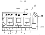
- a display unit 210 has a light emitting element 211 and a graphics pattern display section 260 for displaying a graphics pattern lit by the light emitting element.
- the graphics pattern section 260 is provided with graphics patterns having two types of directions and either one is lit by the light emitting element, thereby producing directionality. For the game machine 1 at which an event occurs, a graphics pattern may be lit without directionality. That is, the graphics pattern display section 260 has a graphics pattern showing directionality from left to right and a graphics pattern showing directionality from right to left and selectively lights either of them by the light emitting element in response to an instruction from the display control means 300.
- each display unit is made of a panel display
- a drive circuit (not shown) having a similar configuration to that shown in Figure 8 is used. That is, it can be provided with a memory which stores image data for generating graphics displayed on the screen of the panel display and display means.
- the display controller of the game machine 1 corresponding thereto can also be used.
- a still further embodiment of the invention is as shown in Figure 9.
- a system according to the embodiment has a display device 222 in each game machine 1 and a display controller (not shown) for controlling the operation of the display device 222.
- the display controller comprises event occurrence information read means 301, when a signal indicating that any game machine in the corresponding game machine row is placed in a predetermined specific condition is input, for reading information indicating the position of the game machine, distribution means 302 for distributing the display devices 222 into those positioned to the left, when facing the game machine row, and those positioned to the right, with the position corresponding to the position indicated by the information as reference, and control means for controlling so as to cause the display devices 222 positioned to the left to display in a display mode representing directionality from the left end to the reference position and to cause the display devices 222 positioned to the right to display in a display mode representing directionality from the right end to the reference position, as shown in Figure 6.
- the display system functions only when a personnel call source has occurred, but the invention is not limited to this mode.
- it may also serve as fever display when a game machine is placed in a winning condition. That is, when a player wins a game play, a winning signal is output from the game machine.
- the display control means causes graphics patterns or the like described above to move on display in a fever display color, for example, in blue.
- each of the display units 210 is provided with a plurality of light emitting elements 211, but the invention is not thus limited to it.
- one display unit 210 may be provided with one light emitting element 211.
- the display drive circuit 250 is not provided for each display unit 210 and one display drive circuit is assigned to a plurality of display units.
- a personnel call source such as a problem occurs at any game machine
- personnel in the game house can be informed immediately and precisely of the game machine where the source such as the problem has occurred.
- Events such as a winning game play can also be displayed in a similar manner.
Landscapes
- Physics & Mathematics (AREA)
- General Physics & Mathematics (AREA)
- Engineering & Computer Science (AREA)
- Multimedia (AREA)
- Pinball Game Machines (AREA)
- Display Devices Of Pinball Game Machines (AREA)
- Control Of El Displays (AREA)
- Control Of Indicators Other Than Cathode Ray Tubes (AREA)
- Electroluminescent Light Sources (AREA)
- Devices For Indicating Variable Information By Combining Individual Elements (AREA)
Abstract
Applications Claiming Priority (5)
| Application Number | Priority Date | Filing Date | Title |
|---|---|---|---|
| JP34369691 | 1991-12-25 | ||
| JP343696/91 | 1991-12-25 | ||
| JP3534092 | 1992-02-21 | ||
| JP35340/92 | 1992-02-21 | ||
| PCT/JP1992/001705 WO1993012849A1 (fr) | 1991-12-25 | 1992-12-25 | Systeme d'affichage pour ilot de machines a sous |
Publications (2)
| Publication Number | Publication Date |
|---|---|
| EP0619128A1 true EP0619128A1 (fr) | 1994-10-12 |
| EP0619128A4 EP0619128A4 (fr) | 1995-12-27 |
Family
ID=26374320
Family Applications (1)
| Application Number | Title | Priority Date | Filing Date |
|---|---|---|---|
| EP93900438A Withdrawn EP0619128A4 (fr) | 1991-12-25 | 1992-12-25 | Systeme d'affichage pour ilot de machines a sous. |
Country Status (6)
| Country | Link |
|---|---|
| US (1) | US5472195A (fr) |
| EP (1) | EP0619128A4 (fr) |
| KR (1) | KR940703700A (fr) |
| AU (1) | AU670422B2 (fr) |
| CA (1) | CA2126559C (fr) |
| WO (1) | WO1993012849A1 (fr) |
Cited By (2)
| Publication number | Priority date | Publication date | Assignee | Title |
|---|---|---|---|---|
| WO2002007838A3 (fr) * | 2000-07-24 | 2002-05-02 | Kevin Docherty | Procede et systeme de gestion de l'entretien de machines de jeu |
| EP1365366A3 (fr) * | 2002-05-21 | 2005-01-19 | Aruze Co., Ltd. | Machine de jeu |
Families Citing this family (54)
| Publication number | Priority date | Publication date | Assignee | Title |
|---|---|---|---|---|
| WO1995005876A1 (fr) * | 1993-08-27 | 1995-03-02 | Christopher Russell Byrne | Super-keno |
| GB2345171B (en) * | 1995-12-19 | 2000-08-09 | Brad Wendkos | A communications system and interactive computerized methods and apparatus for conducting an incentive awards program |
| US5826882A (en) * | 1996-11-12 | 1998-10-27 | Vector Slot Machine Company, L.L.C. | Slot cabinet and base unit therefor |
| US5908354A (en) * | 1997-02-07 | 1999-06-01 | Okuniewicz; Douglas M. | Programmable sound card for electronic devices |
| US8986105B2 (en) * | 1997-02-07 | 2015-03-24 | Douglas M. Okuniewicz | Supplemental bonusing system for an electronic gaming device |
| US9728040B2 (en) * | 1997-02-07 | 2017-08-08 | Aim Management, Inc. | Printing and dispensing system for an electronic gaming device that provides an undisplayed outcome |
| US7871325B2 (en) * | 1997-02-07 | 2011-01-18 | Okuniewicz Douglas M | Means for generating a supplement bonus for an electronic gaming device |
| US6840860B1 (en) * | 1997-02-07 | 2005-01-11 | Douglas M. Okuniewicz | Printing and dispensing bonusing system for gaming devices |
| US8113935B2 (en) | 1997-03-12 | 2012-02-14 | Igt | System and method for presenting payout ranges and audiovisual clips at a gaming device |
| US6234896B1 (en) * | 1997-04-11 | 2001-05-22 | Walker Digital, Llc | Slot driven video story |
| US6050895A (en) * | 1997-03-24 | 2000-04-18 | International Game Technology | Hybrid gaming apparatus and method |
| US8328624B2 (en) * | 1997-04-11 | 2012-12-11 | Igt | Slot driven video story |
| JPH119761A (ja) * | 1997-04-30 | 1999-01-19 | Aruze Kk | 遊技機 |
| US6071192A (en) * | 1997-05-20 | 2000-06-06 | Casino Data Systems | Gaming machine display simulation of minting coins |
| ZA977451B (en) * | 1997-06-30 | 1999-05-19 | Mandiro Trading Ltd | Multiplayer interactive video gaming device |
| JPH11169505A (ja) * | 1997-12-10 | 1999-06-29 | Aruze Corp | 遊技用表示装置及び遊技機 |
| AU3478199A (en) * | 1998-04-13 | 1999-11-01 | Game Data, Inc. | Casino game with combination display |
| AUPP518498A0 (en) * | 1998-08-10 | 1998-09-03 | Aristocrat Leisure Industries Pty Ltd | Gaming machine with transparent sprites |
| US7008324B1 (en) * | 1998-10-01 | 2006-03-07 | Paltronics, Inc. | Gaming device video display system |
| US6605001B1 (en) | 1999-04-23 | 2003-08-12 | Elia Rocco Tarantino | Dice game in which categories are filled and scores awarded |
| US7081050B2 (en) * | 1999-04-23 | 2006-07-25 | Colepat, Llc | Method of playing a multi-player game |
| US20020055381A1 (en) | 1999-04-23 | 2002-05-09 | Tarantino Elia Rocco | Multi-player game and gaming system |
| US6656047B1 (en) | 1999-04-23 | 2003-12-02 | Colepat, Llc | Computer-controlled gaming apparatus and method |
| US7291067B2 (en) | 1999-04-23 | 2007-11-06 | Colepat, Llc | Method and system for playing a multi-player game |
| WO2001019475A1 (fr) | 1999-09-13 | 2001-03-22 | International Game Technology | Dispositif de remise en jeu d'un bonus et procede de jeu presentant flexibilite et interet |
| US8961304B2 (en) * | 1999-09-17 | 2015-02-24 | Aristocrat Technologies, Inc. | Gaming device video display system |
| US6267669B1 (en) | 1999-11-29 | 2001-07-31 | International Game Technology | Hybrid gaming apparatus and method |
| AU2002327664B2 (en) * | 2001-09-18 | 2008-09-04 | Igt | Gaming System whereby game contents is changed based on recorded data about different players |
| US7785194B2 (en) * | 2001-09-18 | 2010-08-31 | Igt | Player specific rewards |
| US6923720B2 (en) * | 2002-01-09 | 2005-08-02 | Wms Gaming Inc. | Synchronization of display indicia on standalone gaming machines |
| US20030144022A1 (en) * | 2002-01-31 | 2003-07-31 | Richard Hatch | Mobile communications device for playing a game |
| JP2004024529A (ja) * | 2002-06-25 | 2004-01-29 | Aruze Corp | 遊技機 |
| US20040209676A1 (en) * | 2002-11-18 | 2004-10-21 | Takahiro Onishi | Gaming machine |
| JP2004166879A (ja) * | 2002-11-19 | 2004-06-17 | Aruze Corp | 遊技機 |
| US7867085B2 (en) * | 2003-01-16 | 2011-01-11 | Wms Gaming Inc. | Gaming machine environment having controlled audio and visual media presentation |
| US20040224758A1 (en) * | 2003-04-30 | 2004-11-11 | Kazuo Okada | Gaming machine |
| US8585479B2 (en) | 2003-10-20 | 2013-11-19 | Tipping Point Group, Llc | System to decode video signal from electronic gaming device and to determine play information |
| US20050130732A1 (en) * | 2003-12-12 | 2005-06-16 | Rothschild Wayne H. | Random bonus delivery mechanism for a gaming system |
| US7922578B2 (en) | 2005-01-11 | 2011-04-12 | Okuniewicz Douglas M | Method for providing an undisplayed outcome of an electronic gaming device |
| US10540842B2 (en) | 2005-01-11 | 2020-01-21 | Aim Management, Inc. | Data storage system for an electronic gaming device |
| US8337309B2 (en) | 2005-01-11 | 2012-12-25 | Okuniewicz Douglas M | Data based awards for an electronic gaming device |
| US20060166727A1 (en) * | 2005-01-24 | 2006-07-27 | Wms Gaming Inc. | Gaming machine with proximity-sensitive input device |
| EP1954362A4 (fr) | 2005-11-22 | 2011-08-24 | Igt Reno Nev | Jeu reglemente mise en scene de jeux a actes multiples regulated gaming-staging multi-act games |
| US7748458B2 (en) | 2006-02-27 | 2010-07-06 | Geosierra Llc | Initiation and propagation control of vertical hydraulic fractures in unconsolidated and weakly cemented sediments |
| JP2007325884A (ja) * | 2006-06-09 | 2007-12-20 | Aruze Corp | 遊技機 |
| US8221215B2 (en) | 2006-09-26 | 2012-07-17 | Igt | Providing and redeeming partial wagering game outcomes |
| US8177637B2 (en) | 2006-11-09 | 2012-05-15 | Igt | Button panel control for a gaming machine |
| US8096884B2 (en) | 2006-11-09 | 2012-01-17 | Igt | Gaming machine with adjustable button panel |
| US7833102B2 (en) | 2006-11-09 | 2010-11-16 | Igt | Gaming machine with consolidated peripherals |
| US20110151965A1 (en) * | 2009-12-17 | 2011-06-23 | Elia Rocco Tarantino | Aggregate game play jackpot game |
| KR20120017243A (ko) * | 2010-08-18 | 2012-02-28 | 삼성전기주식회사 | 전자 선반 라벨 시스템 및 이를 이용한 통신 방법 |
| JP2012100892A (ja) * | 2010-11-10 | 2012-05-31 | Universal Entertainment Corp | ゲーミングマシン |
| US20150018072A1 (en) | 2013-07-09 | 2015-01-15 | Igt | Gaming system and method for resuming a skill-based game after an interruption event |
| CN111260860B (zh) * | 2020-01-21 | 2021-12-07 | 江西光正金属设备集团有限公司 | 一种夏季防水阻止水果淋雨腐烂的快递柜 |
Family Cites Families (11)
| Publication number | Priority date | Publication date | Assignee | Title |
|---|---|---|---|---|
| GB2062922B (en) * | 1979-10-27 | 1983-12-07 | Jpm Automatic Machines Ltd | Coin-operated or coin-feed gaming or amusement machines |
| GB2097160B (en) * | 1981-02-06 | 1984-05-10 | Barcrest Ltd | Entertainment machines |
| GB2157047A (en) * | 1984-04-05 | 1985-10-16 | David Jones | Entertainment machines |
| GB8617044D0 (en) * | 1986-07-12 | 1986-08-20 | Bell Fruit Mfg Co Ltd | Gaming & amusement machines |
| JPH03202084A (ja) * | 1989-12-28 | 1991-09-03 | Nippon Rejiyaa Kaade Syst Kk | パチンコ機等における情報伝達装置 |
| JPH07106261B2 (ja) * | 1990-05-10 | 1995-11-15 | 株式会社三洋物産 | パチンコ機 |
| JPH0437486A (ja) * | 1990-05-31 | 1992-02-07 | Furukawa Electric Co Ltd:The | 金属複合条の製造方法 |
| JPH087900Y2 (ja) * | 1990-07-26 | 1996-03-06 | ユーエフ産業株式会社 | ゲーム機の入賞表示装置 |
| JP2574057B2 (ja) * | 1990-08-06 | 1997-01-22 | 株式会社ニューギン | 図柄組合せ表示式のパチンコ遊技機 |
| JP2869830B2 (ja) * | 1991-12-25 | 1999-03-10 | 株式会社エース電研 | 遊技装置 |
| US5702303A (en) * | 1992-03-10 | 1997-12-30 | Kabushiki Kaisha Ace Denken | Game machine having a playing display screen |
-
1992
- 1992-12-25 AU AU31725/93A patent/AU670422B2/en not_active Ceased
- 1992-12-25 EP EP93900438A patent/EP0619128A4/fr not_active Withdrawn
- 1992-12-25 WO PCT/JP1992/001705 patent/WO1993012849A1/fr not_active Ceased
- 1992-12-25 US US08/256,114 patent/US5472195A/en not_active Expired - Fee Related
- 1992-12-25 CA CA002126559A patent/CA2126559C/fr not_active Expired - Fee Related
- 1992-12-25 KR KR1019940702221A patent/KR940703700A/ko not_active Withdrawn
Non-Patent Citations (2)
| Title |
|---|
| No further relevant documents disclosed * |
| See also references of WO9312849A1 * |
Cited By (5)
| Publication number | Priority date | Publication date | Assignee | Title |
|---|---|---|---|---|
| WO2002007838A3 (fr) * | 2000-07-24 | 2002-05-02 | Kevin Docherty | Procede et systeme de gestion de l'entretien de machines de jeu |
| EP1365366A3 (fr) * | 2002-05-21 | 2005-01-19 | Aruze Co., Ltd. | Machine de jeu |
| US7288026B2 (en) | 2002-05-21 | 2007-10-30 | Aruze Co., Ltd. | Gaming apparatus |
| AU2003204281B2 (en) * | 2002-05-21 | 2009-08-20 | Universal Entertainment Corporation | Gaming Apparatus |
| US8475271B2 (en) | 2002-05-21 | 2013-07-02 | Universal Entertainment Corporation | Gaming apparatus |
Also Published As
| Publication number | Publication date |
|---|---|
| CA2126559A1 (fr) | 1993-07-08 |
| US5472195A (en) | 1995-12-05 |
| CA2126559C (fr) | 1996-05-28 |
| KR940703700A (ko) | 1994-12-12 |
| WO1993012849A1 (fr) | 1993-07-08 |
| AU670422B2 (en) | 1996-07-18 |
| AU3172593A (en) | 1993-07-28 |
| EP0619128A4 (fr) | 1995-12-27 |
Similar Documents
| Publication | Publication Date | Title |
|---|---|---|
| US5472195A (en) | Display system at a game machine island | |
| US4874173A (en) | Slot machine | |
| US5526327A (en) | Spatial displacement time display | |
| US6790140B1 (en) | Game machine | |
| FI94099C (fi) | Näyttöjärjestelmä tietoavusteista bingopeliä varten | |
| JPH10503095A (ja) | パズル装置 | |
| USRE40340E1 (en) | Electronic hand held logic game | |
| US5848788A (en) | Electro-magnetic game board | |
| EP0005930A1 (fr) | Appareils de divertissement | |
| JP4409149B2 (ja) | スロットマシン | |
| US4436308A (en) | Bingo game display | |
| JP4563431B2 (ja) | 回胴式遊技機 | |
| JP2001087458A (ja) | 遊技機 | |
| JP2005137783A (ja) | 遊技機 | |
| JP2927907B2 (ja) | パチンコゲーム機 | |
| US4408762A (en) | Electronic pinball game | |
| US8876585B1 (en) | Method and apparatus for electronic puzzle device | |
| JPH0824735B2 (ja) | 遊技機島における表示装置 | |
| JPH0363082A (ja) | パチンコ機の入賞表示装置 | |
| JP3732368B2 (ja) | 表示装置及びこれを用いた遊技機 | |
| JPWO1993012849A1 (ja) | 遊技機島における表示装置 | |
| JPH0541731Y2 (fr) | ||
| JP3272487B2 (ja) | 遊技機 | |
| JPH0524385Y2 (fr) | ||
| JPH0473079A (ja) | 遊技機の絵柄表示部 |
Legal Events
| Date | Code | Title | Description |
|---|---|---|---|
| PUAI | Public reference made under article 153(3) epc to a published international application that has entered the european phase |
Free format text: ORIGINAL CODE: 0009012 |
|
| 17P | Request for examination filed |
Effective date: 19940713 |
|
| AK | Designated contracting states |
Kind code of ref document: A1 Designated state(s): DE FR GB MC |
|
| A4 | Supplementary search report drawn up and despatched |
Effective date: 19951113 |
|
| AK | Designated contracting states |
Kind code of ref document: A4 Designated state(s): DE FR GB MC |
|
| 17Q | First examination report despatched |
Effective date: 19970207 |
|
| GRAG | Despatch of communication of intention to grant |
Free format text: ORIGINAL CODE: EPIDOS AGRA |
|
| STAA | Information on the status of an ep patent application or granted ep patent |
Free format text: STATUS: THE APPLICATION HAS BEEN WITHDRAWN |
|
| 18W | Application withdrawn |
Withdrawal date: 19980407 |