EP0619692B1 - ContrÔle de la température dans un dispositif de chauffage par induction à haute-fréquence - Google Patents
ContrÔle de la température dans un dispositif de chauffage par induction à haute-fréquence Download PDFInfo
- Publication number
- EP0619692B1 EP0619692B1 EP94302487A EP94302487A EP0619692B1 EP 0619692 B1 EP0619692 B1 EP 0619692B1 EP 94302487 A EP94302487 A EP 94302487A EP 94302487 A EP94302487 A EP 94302487A EP 0619692 B1 EP0619692 B1 EP 0619692B1
- Authority
- EP
- European Patent Office
- Prior art keywords
- high frequency
- resonance
- power supply
- induction heating
- supply unit
- Prior art date
- Legal status (The legal status is an assumption and is not a legal conclusion. Google has not performed a legal analysis and makes no representation as to the accuracy of the status listed.)
- Expired - Lifetime
Links
Images


Classifications
-
- G—PHYSICS
- G01—MEASURING; TESTING
- G01K—MEASURING TEMPERATURE; MEASURING QUANTITY OF HEAT; THERMALLY-SENSITIVE ELEMENTS NOT OTHERWISE PROVIDED FOR
- G01K7/00—Measuring temperature based on the use of electric or magnetic elements directly sensitive to heat ; Power supply therefor, e.g. using thermoelectric elements
- G01K7/36—Measuring temperature based on the use of electric or magnetic elements directly sensitive to heat ; Power supply therefor, e.g. using thermoelectric elements using magnetic elements, e.g. magnets, coils
- G01K7/38—Measuring temperature based on the use of electric or magnetic elements directly sensitive to heat ; Power supply therefor, e.g. using thermoelectric elements using magnetic elements, e.g. magnets, coils the variations of temperature influencing the magnetic permeability
-
- F—MECHANICAL ENGINEERING; LIGHTING; HEATING; WEAPONS; BLASTING
- F01—MACHINES OR ENGINES IN GENERAL; ENGINE PLANTS IN GENERAL; STEAM ENGINES
- F01N—GAS-FLOW SILENCERS OR EXHAUST APPARATUS FOR MACHINES OR ENGINES IN GENERAL; GAS-FLOW SILENCERS OR EXHAUST APPARATUS FOR INTERNAL-COMBUSTION ENGINES
- F01N3/00—Exhaust or silencing apparatus having means for purifying, rendering innocuous, or otherwise treating exhaust
- F01N3/08—Exhaust or silencing apparatus having means for purifying, rendering innocuous, or otherwise treating exhaust for rendering innocuous
- F01N3/10—Exhaust or silencing apparatus having means for purifying, rendering innocuous, or otherwise treating exhaust for rendering innocuous by thermal or catalytic conversion of noxious components of exhaust
- F01N3/18—Exhaust or silencing apparatus having means for purifying, rendering innocuous, or otherwise treating exhaust for rendering innocuous by thermal or catalytic conversion of noxious components of exhaust characterised by methods of operation; Control
- F01N3/20—Exhaust or silencing apparatus having means for purifying, rendering innocuous, or otherwise treating exhaust for rendering innocuous by thermal or catalytic conversion of noxious components of exhaust characterised by methods of operation; Control specially adapted for catalytic conversion
- F01N3/2006—Periodically heating or cooling catalytic reactors, e.g. at cold starting or overheating
- F01N3/2013—Periodically heating or cooling catalytic reactors, e.g. at cold starting or overheating using electric or magnetic heating means
-
- F—MECHANICAL ENGINEERING; LIGHTING; HEATING; WEAPONS; BLASTING
- F01—MACHINES OR ENGINES IN GENERAL; ENGINE PLANTS IN GENERAL; STEAM ENGINES
- F01N—GAS-FLOW SILENCERS OR EXHAUST APPARATUS FOR MACHINES OR ENGINES IN GENERAL; GAS-FLOW SILENCERS OR EXHAUST APPARATUS FOR INTERNAL-COMBUSTION ENGINES
- F01N9/00—Electrical control of exhaust gas treating apparatus
-
- H—ELECTRICITY
- H05—ELECTRIC TECHNIQUES NOT OTHERWISE PROVIDED FOR
- H05B—ELECTRIC HEATING; ELECTRIC LIGHT SOURCES NOT OTHERWISE PROVIDED FOR; CIRCUIT ARRANGEMENTS FOR ELECTRIC LIGHT SOURCES, IN GENERAL
- H05B6/00—Heating by electric, magnetic or electromagnetic fields
- H05B6/02—Induction heating
- H05B6/06—Control, e.g. of temperature, of power
-
- H—ELECTRICITY
- H05—ELECTRIC TECHNIQUES NOT OTHERWISE PROVIDED FOR
- H05B—ELECTRIC HEATING; ELECTRIC LIGHT SOURCES NOT OTHERWISE PROVIDED FOR; CIRCUIT ARRANGEMENTS FOR ELECTRIC LIGHT SOURCES, IN GENERAL
- H05B2213/00—Aspects relating both to resistive heating and to induction heating, covered by H05B3/00 and H05B6/00
- H05B2213/07—Heating plates with temperature control means
-
- Y—GENERAL TAGGING OF NEW TECHNOLOGICAL DEVELOPMENTS; GENERAL TAGGING OF CROSS-SECTIONAL TECHNOLOGIES SPANNING OVER SEVERAL SECTIONS OF THE IPC; TECHNICAL SUBJECTS COVERED BY FORMER USPC CROSS-REFERENCE ART COLLECTIONS [XRACs] AND DIGESTS
- Y02—TECHNOLOGIES OR APPLICATIONS FOR MITIGATION OR ADAPTATION AGAINST CLIMATE CHANGE
- Y02T—CLIMATE CHANGE MITIGATION TECHNOLOGIES RELATED TO TRANSPORTATION
- Y02T10/00—Road transport of goods or passengers
- Y02T10/10—Internal combustion engine [ICE] based vehicles
- Y02T10/12—Improving ICE efficiencies
-
- Y—GENERAL TAGGING OF NEW TECHNOLOGICAL DEVELOPMENTS; GENERAL TAGGING OF CROSS-SECTIONAL TECHNOLOGIES SPANNING OVER SEVERAL SECTIONS OF THE IPC; TECHNICAL SUBJECTS COVERED BY FORMER USPC CROSS-REFERENCE ART COLLECTIONS [XRACs] AND DIGESTS
- Y02—TECHNOLOGIES OR APPLICATIONS FOR MITIGATION OR ADAPTATION AGAINST CLIMATE CHANGE
- Y02T—CLIMATE CHANGE MITIGATION TECHNOLOGIES RELATED TO TRANSPORTATION
- Y02T10/00—Road transport of goods or passengers
- Y02T10/10—Internal combustion engine [ICE] based vehicles
- Y02T10/40—Engine management systems
Definitions
- the present invention relates to a heating temperature control method in high frequency induction heating and high frequency induction heating temperature control apparatus, and more particularly to a control method and apparatus suitable for accurately controlling a heating temperature of an object to be heated when a high frequency induction heating coil is used to high frequency induction heat the object.
- a catalytic converter disposed on the way of an exhaust pipe of an automobile to purify exhaust gas is heated by the exhaust gas to a high temperature during traveling of the automobile and accordingly the purification of the exhaust gas by the catalytic converter is performed effectively, but while the catalytic converter is at the normal temperature upon starting of an engine of the automobile the purification is not performed effectively. Accordingly, in order to perform the purification of exhaust gas upon starting of the engine sufficiently, it is necessary to heat the catalytic converter forcedly upon starting of the engine.
- a DC current flows in the catalytic converter directly to utilize the Joule heat.
- Fig. 12 illustrates a control apparatus 50 for carrying out the conventional heating method.
- the apparatus 50 serves to heat a catalytic converter (object to be heated) 51 to a previously set temperature.
- the conventional temperature control apparatus 50 is configured to supply electric power from a DC power supply 52 to the catalytic converter 51 constituting the object to be heated and Joule-heat it and to detect a heating temperature of the catalytic converter 51 by means of a thermocouple temperature sensor 53 attached to the catalytic converter 51.
- the thermocouple temperature sensor 53 produces a voltage signal proportional to a detected temperature to supply it to a comparator 54, which compares the voltage signal with a predetermined reference voltage.
- thermocouple temperature sensor 53 When the temperature detected by the thermocouple temperature sensor 53 exceeds a predetermined reference voltage, the comparator 54 produces a predetermined control signal. The control signal switches a power switch 55 from an on state to an off state to cut off supply of electric power to the catalytic converter 51, so that heating of the catalytic converter 51 is stopped.
- the catalytic converter 51 is heated to the predetermined set temperature and is controlled not to exceed the set temperature.
- thermocouple temperature sensor 53 is used as detection means of the heating temperature of the catalytic converter 51 and the thermocouple temperature sensor 53 is brought into contact with the catalytic converter 51 to detect the temperature thereof, there are defects as follows. During traveling of the automobile (during continuous operation of an engine), the catalytic converter 51 is heated to a high temperature by exhaust gas heated at a high temperature and the thermocouple temperature sensor 53 is also heated to a high temperature correspondingly. Accordingly, the thermocouple temperature sensor 53 tends to be deteriorated in its early stage. Hence, the durability of the thermocouple temperature sensor 53 comes into question and there is a possibility that an accurate temperature can not be detected.
- thermocouple temperature sensor 53 In addition, mechanical vibration is transmitted to the thermocouple temperature sensor 53 through the catalytic converter 51 easily, so that the thermocouple temperature sensor 53 is separated from the catalytic converter 51 due to large mechanical vibration and there is a possibility that the thermocouple temperature sensor can not attain the temperature detection function.
- a heating time is set to a predetermined time by a timer and high frequency induction heating is performed for the predetermined time without using the thermocouple temperature sensor 53, while in this case the heating time is scattered due to variation in dimension and quality of material of the object to be heated and deterioration in aging of the quality of material, so that high frequency induction heating with high accuracy can not be attained.
- the present invention has been made in order to solve the above problems and an aim of the present invention is to provide a heating temperature control method in high frequency induction heating and a high frequency induction heating temperature control apparatus capable of detecting a temperature of an object to be heated accurately in the non-contact manner without using a contact type thermocouple temperature sensor to high frequency induction to heat the object to a desired temperature and having excellent durability.
- WO 82/02593 discloses a high frequency induction heating temperature control method in accordance with the preamble of claim 1.
- the present invention provides a heating temperature control method in high frequency induction heating, wherein a resonance circuit comprising a high frequency induction heating coil is supplied with electric power from a high frequency power supply unit, the resonance circuit is set to a resonance state, and a heating temperature of an object to be heated by the coil is controlled on the basis of a resonance frequency of the resonance circuit, the resonance frequency varying as a function of the temperature of the object, characterised in that the resonance circuit is a series resonance circuit including a condenser between the power supply unit and the coil, and the method includes controlling the power supply unit so that a phase of a high frequency voltage produced by the power supply unit is substantially coincident with a phase of a high frequency current flowing through the coil, thereby maintaining the resonance circuit in a resonance state.
- the power supply unit comprises an inverter for changing direct current into high frequency alternating current, and the method comprises the steps of:
- the object heated may be a catalytic converter for purifying exhaust gas of an automobile in the above heating temperature control method.
- control apparatus comprises:
- Operation of the present invention is as follows. That is, the resonance frequency in the case where the resonance circuit including the high frequency induction heating coil is set to the resonance state is varied with the increased temperature of the object to be heated. Accordingly, variation of the temperature of the object to be heated is previously obtained for a parameter of the resonance frequency in the case where the resonance circuit is always set to the resonance state, so that a heating temperature of the object to be heated can be detected on the basis of the resonance frequency and heating of the object can be stopped in response to the detection to control the heating temperature.
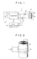
- Fig. 1 schematically illustrates a portion of a high frequency induction heating temperature control apparatus 1 used to implement a heating temperature control method in high frequency induction heating according to the present invention.
- numeral 2 denotes a DC power supply
- 3 an inverter for converting electric power supplied from the DC power supply 2 into high frequency electric power
- 4 a resonance circuit constituted by a series circuit of a resonance condenser 5 and a high frequency induction heating coil 6 supplied with the high frequency electric power from the inverter 3
- 7 a current transformer (CT) for detecting a high frequency current flowing through the high frequency induction heating coil 6
- 8 a PLL oscillation circuit supplied with a current flowing through the current transformer 7 and an output voltage of the inverter 3.
- CT current transformer
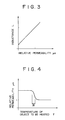
- numeral 9 denotes an object to be high frequency induction heated by the high frequency induction heating coil 6, and the object to be heated of the embodiment is a catalytic converter for purifying exhaust gas used in an exhaust pipe of an automobile.
- the catalytic converter 9 includes a sheet of steel plate wound spirally and having a catalytic layer of platinum or the like formed on the surface thereof.
- the high frequency induction hating coil 6 is disposed about the catalytic converter 9 concentrically.
- the inverter 3 is controlled to be operated on the basis of a frequency f of a control signal produced by the PLL oscillation circuit 8 and the inverter 3 produces high frequency electric power having the same frequency as the frequency f so that the resonance circuit 4 is always set to the resonance state.
- an impedance Zr of the high frequency induction heating coil 6 is expressed as described by the following equation (a)
- an impedance Zo as viewed from the power supply side is expressed as described by the following equation (b) since the resonance condenser C and the high frequency induction heating coil 6 constitute a series circuit.
- Zr r + i ⁇ 2 ⁇ f ⁇ L ( a )
- r is a pure resistance component of the coil 6 when the catalytic converter 9 is inserted into the high frequency induction heating coil 6
- L is an inductance of the coil 6
- f is a frequency.
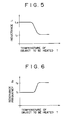
- a relation of the relative permeability ⁇ s and a temperature T of the object to be heated is in correlative relation as shown in Fig. 4 and has a linear function in its specific area R as shown in the following equation (f).
- a relation of the temperature T of the object and the inductance L of the high frequency induction heating coil 6 is as shown in Fig. 5.
- ⁇ s F ( T ) ( f )
- the temperature T and the resonance frequency f o have one-to-one correspondence to each other in the specific range. Accordingly, it can be understood that the temperature T of the object to be heated (catalytic converter 9) can be detected on the basis of the resonance frequency f o .
- the resonance circuit 4 is set to the resonance state always by means of operation of the PLL oscillation circuit 8 so as to follow the variation of the relative permeability. In this manner, when the resonance frequency is gradually changed and reaches a predetermined frequency, supply of electric power from the high frequency power supply unit 10 is stopped.
- Fig. 7 schematically illustrates a definite example using the circuit of Fig. 1, that is, a high frequency induction heating control apparatus 12 according to the present invention.
- Fig. 7 like elements to those of Fig. 1 are designated by like numerals and its detailed description is omitted.
- the apparatus 12 of this example includes the high frequency power supply unit 10 composed of the DC power supply 2 and the inverter 3, the resonance circuit 4 composed of the resonance condenser 5 and the high frequency induction heating coil 6, a phase control circuit 15 composed of the PLL oscillation circuit 8 and first and second gate circuits 13 and 14, a flag signal generating circuit 16 for generating a predetermined flag signal on the basis of an output frequency of the PLL oscillation circuit 8, and a flip-flop 18 for producing a change-over signal for changing over a change-over switch 17 for stopping of the heating from an on state to an off state on the basis of the flag signal.
- the PLL oscillation circuit 8 includes a phase comparator 20 for comparing a phase of the high frequency voltage v from the inverter 3 with a phase of the high frequency current i from the current transformer 7, a low pass filter 21 through which an output of the phase comparator 20 passes, and a voltage controlled oscillator 22 which is operated on the basis of a control voltage from the low pass filter 21.
- the flag signal generating circuit 16 includes a frequency counter 24 supplied with an output of the voltage controlled oscillator 22 of the PLL oscillation circuit 8, a frequency setting device 25 capable of setting a desired frequency, and a frequency comparator 26 for comparing an output of the frequency counter 24 with an output of the frequency setting device 25 to supply the flag signal to the flip-flop 18 when a predetermined condition is satisfied.
- the output of the voltage controlled oscillator 22 of the PLL oscillation circuit 8 is supplied to the first gate circuit 13.
- the second gate circuit 14 is supplied with an output signal of the flip-flop 18 and is also supplied with a predetermined input voltage +V through the change-over switch 17.
- an output signal from the second gate circuit 14 is supplied to the first gate circuit 13 and an output signal of the first gate circuit 13 is supplied to the inverter 3 as the frequency control signal.
- the change-over switch is turned on and the output frequency of the PLL oscillation circuit 8 is supplied through the first gate circuit 13 to the inverter 3.
- the high frequency voltage v is supplied to the resonance circuit 4, so that the high frequency current flows into the high frequency induction heating coil 6 to thereby induction-heat the catalytic converter 9 (object to be heated) inserted into the high frequency induction heating coil 6 so that temperature of the catalytic converter is increased.
- the catalytic converter 9 is gradually heated from its outer periphery as shown in Fig. 8 and the temperature T of the catalytic converter 9 is varied with the elapse of the heating time t as shown in Fig. 9.
- the high frequency current flowing through the high frequency induction heating coil 6 is supplied to the phase comparator 20 through the current transformer 7.
- the phase comparator 20 compares the phase of the high frequency current i from the current transformer 7 with the phase of the output voltage v from the inverter 3 to produce the voltage signal proportional to a phase difference between the high frequency current i and the output voltage v.
- An output voltage of the phase comparator 20 is supplied to the low pass filter 21 in which harmonics of the output voltage are removed to be converted into a DC voltage.
- the DC voltage is supplied to the voltage controlled oscillator 22.
- the PLL oscillation circuit 8 is operated so that the frequency f of the oscillation output of the voltage controlled oscillator 22 is made high when the phase of the high frequency current i is advanced ( ⁇ 0°)as compared with the phase of the output voltage v and on the contrary the frequency f is made low when the phase of the high frequency current i is delayed ( ⁇ >0°) as compared with the phase of the output voltage v.
- the oscillation circuit 4 including the series circuit of the resonance condenser 5 and the high frequency induction heating 6, when the frequency of the power supply voltage supplied from the inverter 3 (that is, the oscillation frequency f of the voltage controlled oscillator 22) is made high, the phase of the high frequency current i is delayed as compared with the phase of the output voltage v and on the contrary when the frequency f of the power supply voltage is made low, the phase of the high frequency current i is advanced as compared with the phase of the output voltage v.
- the output voltage of the phase comparator 20 in the PLL oscillation circuit 8 is in the negative feedback state with respect to the oscillation frequency f of the voltage controlled oscillator 22 and finally the phase difference ⁇ of the output voltage v and the high frequency current i automatically controlled to be equal to 0°, that is, the resonance circuit 4 is automatically controlled to be in the resonance state.
- the relative permeability ⁇ s is varied with increase of the heating temperature of the catalytic converter 9 as described above to thereby shift the resonance frequency f o , while the resonance state is always set automatically by means of the phase lock operation by the PLL oscillation circuit 8 and the following operation to the resonance state is automatically performed for a parameter of the oscillation frequency f.
- the resonance frequency f o is varied with the elapse of the heating time t as shown in Fig. 10.
- the output frequency of the voltage controlled oscillator 22 is supplied to the frequency counter 24 so that the oscillation frequency f is converted into a digital signal by the frequency counter 24.
- the digital signal is supplied to the frequency comparator 26 to be compared with a set value of the frequency setting device 25.
- the setting operation of the set value is made so that a relation of the resonance frequency and the heating temperature in the catalytic converter 9 to be heated is previously obtained and the output frequency of the voltage controlled oscillator is set to be equal to the numerical value of the resonance frequency corresponding to a desired heating temperature.
- the flag signal is generated by the frequency comparator 26 and is supplied to the flip-flop 18 to be held in the flip-flop.
- the flip-flop 18 produces a predetermined heating stop signal in response to the flag signal to be supplied to a controller not shown.
- the heating stop signal is supplied to the second gate circuit 14 and the change-over switch 17 is changed over from the on state to the off state in accordance with the heating stop signal to thereby cut off supply of the electric power +V to the second gate circuit 14. Consequently, the frequency output of the PLL circuit 8 is cut off by the first gate circuit 13 and is not supplied to the inverter 3.
- the resonance circuit 4 can be always set to the resonance state and the catalytic converter 9 can be induction-heated accurately to the desired temperature for a parameter of the resonance frequency f o varied with increase of the heating temperature of the catalytic converter 9. That is, since the temperature T of the catalytic converter 9 has one-to-one correspondence to the resonance frequency f o as shown in Fig. 11, the heating temperature of the catalytic converter 9 can be set to the desired temperature by previously inputting the numerical value of the resonance frequency f o to the frequency setting device 25. Accordingly, it can be prevented exactly that the catalytic converter 9 is heated to the set temperature or is overheated to a temperature higher than the set temperature.
- the object to be heated is the catalytic converter 9, which is a spirally wound body as described above. Accordingly, when the catalytic converter is induction-heated, a large difference in temperature between the outer periphery and the inner periphery thereof occurs. Accordingly, how the heating temperature of the catalytic converter 9 is determined comes into question. Accordingly, for example, the relation of the heating temperature and the resonance frequency may be previously obtained on condition that a temperature of the outer peripheral portion having about 75 % of the whole sectional area perpendicular to an axial line of the catalytic converter 9 exceeds a desired heating temperature.
- the detection means and the detection location of the flag signal, the heating cutting off means based on the flag signal, and the like can be changed properly if necessary.
- the heating temperature control method and the high frequency induction heating temperature control apparatus of the present invention can be applied to not only the catalytic converter 9 but also various objects to be induction heated.
- the resonance circuit having the high frequency induction heating coil is set to the resonance state and the heating temperature of the object to be heated is controlled on the basis of the resonance frequency varied with increased temperature of the object under the resonance state, the object can be heated to a desired temperature accurately and rapidly without using a thermocouple sensor and a timer.
- the heating temperature of the object to be heated is detected for a parameter of the resonance frequency upon the induction heating, the object can be induction-heated with high accuracy and the heating temperature can be detected extremely rapidly as compared with the case where a thermocouple sensor is used, to thereby reduce a necessary time for heating.
- the conventional method using a timer has the possibility that the object is not heated to a predetermined temperature due to scattering of a dimension of the object (deformation in shape and eccentricity) existing in no small quantities and deterioration in material quantity caused by secular change even if a predetermined electric power is supplied, although according to the present invention since the resonance frequency is utilized as the detection means of the heating temperature, the object can be always induction heated to a desired temperature without influence of secular change for individual objects and is very practical.
Landscapes
- Engineering & Computer Science (AREA)
- Chemical & Material Sciences (AREA)
- Mechanical Engineering (AREA)
- Chemical Kinetics & Catalysis (AREA)
- Combustion & Propulsion (AREA)
- Physics & Mathematics (AREA)
- General Engineering & Computer Science (AREA)
- Electromagnetism (AREA)
- Health & Medical Sciences (AREA)
- Toxicology (AREA)
- General Physics & Mathematics (AREA)
- General Induction Heating (AREA)
- Exhaust Gas After Treatment (AREA)
Claims (4)
- Procédé de commande de la température de chauffage lors d'un chauffage par induction à haute fréquence, dans lequel un circuit résonnant comprenant une bobine de chauffage par induction à haute fréquence est alimenté en énergie électrique à partir d'une unité d'alimentation en énergie à haute fréquence, le circuit résonant est mis à un état de résonance, et la température de chauffage d'un objet à chauffer par la bobine est commandée sur la base d'une fréquence de résonance du circuit résonnant, la fréquence de résonance variant en fonction de la température de l'objet, caractérisé en ce que le circuit résonnant est un circuit résonnant monté en série comportant un condensateur entre l'unité d'alimentation en énergie et la bobine, et le procédé comprend la commande de l'unité d'alimentation en énergie de sorte qu'une phase d'une tension à haute fréquence produite par l'unité d'alimentation en énergie coïncide sensiblement avec une phase d'un courant à haute fréquence circulant à travers la bobine, maintenant ainsi le circuit résonnant dans un état de résonance.
- Procédé selon la revendication 1, dans lequel l'unité d'alimentation en énergie comprend un onduleur destiné à transformer le courant continu en courant alternatif à haute fréquence, le procédé comprenant les étapes consistant à:déterminer l'inductance (L) de la bobine en la faisant entrer en résonance à la fréquence élevée;en déduire une perméabilité relative (µs) proportionnelle à l'inductance (L);calculer une température (T) correspondant à la perméabilité relative (µs) selon les données stockées dans une mémoire; et commander la température.
- Procédé selon la revendication 1 ou 2, dans lequel l'objet à chauffer est un convertisseur catalytique destiné à purifier les gaz d'échappement d'une automobile.
- Dispositif de commande de la température de chauffage par induction à haute fréquence comprenant une unité d'alimentation en énergie à haute fréquence (10) et un circuit résonnant (4) devant être alimenté en énergie électrique à partir de l'unité d'alimentation en énergie à haute fréquence (10), le circuit résonnant (4) comprenant une bobine de chauffage par induction à haute fréquence (6) destinée à chauffer par induction à haute fréquence un objet (9),
caractérisé en ce que:le circuit résonnant (4) est un circuit résonnant monté en série comportant un condensateur (5) entre l'unité d'alimentation en énergie à haute fréquence (10) et la bobine de chauffage par induction à haute fréquence (6);par un circuit de commande de phase (15) destiné à commander la fréquence d'alimentation en énergie de l'unité d'alimentation en énergie à haute fréquence (10) de sorte qu'une phase d'une tension à haute fréquence produite par l'unité d'alimentation en énergie à haute fréquence (10) coïncide sensiblement avec une phase d'un courant à haute fréquence circulant à travers la bobine de chauffage par induction à haute fréquence (6), pour mettre toujours le circuit résonnant (4) à un état de résonance; etpar un circuit de production d'un signal indicateur (16) destiné à détecter le moment où l'unité d'alimentation en énergie (10) atteint une fréquence prédéterminée, et à produire un signal indicateur prédéterminé;ce par quoi l'objet (9) est chauffé par induction à haute fréquence de façon continue pendant que le circuit résonnant (4) est toujours mis à l'état de résonance par le circuit de commande (15) en réponse à la variation de l'impédance de la bobine de chauffage par induction à haute fréquence (6) à cause de la température croissante dudit objet (9) qui est chauffé, et l'alimentation en énergie électrique du circuit résonnant (4) depuis l'unité d'alimentation en énergie à haute fréquence (10) est coupée sur la base du signal indicateur produit lorsque la fréquence de résonance du circuit résonnant (4) atteint la fréquence prédéterminée.
Applications Claiming Priority (2)
| Application Number | Priority Date | Filing Date | Title |
|---|---|---|---|
| JP08295493A JP3398172B2 (ja) | 1993-04-09 | 1993-04-09 | 高周波誘導加熱における加熱温度制御方法及び高周波誘導加熱温度制御装置 |
| JP82954/93 | 1993-04-09 |
Publications (3)
| Publication Number | Publication Date |
|---|---|
| EP0619692A2 EP0619692A2 (fr) | 1994-10-12 |
| EP0619692A3 EP0619692A3 (fr) | 1994-11-17 |
| EP0619692B1 true EP0619692B1 (fr) | 1998-12-16 |
Family
ID=13788621
Family Applications (1)
| Application Number | Title | Priority Date | Filing Date |
|---|---|---|---|
| EP94302487A Expired - Lifetime EP0619692B1 (fr) | 1993-04-09 | 1994-04-08 | ContrÔle de la température dans un dispositif de chauffage par induction à haute-fréquence |
Country Status (4)
| Country | Link |
|---|---|
| US (1) | US5477035A (fr) |
| EP (1) | EP0619692B1 (fr) |
| JP (1) | JP3398172B2 (fr) |
| DE (1) | DE69415200T2 (fr) |
Families Citing this family (47)
| Publication number | Priority date | Publication date | Assignee | Title |
|---|---|---|---|---|
| CH690252A5 (de) * | 1995-04-27 | 2000-06-15 | Buehler Ag | Vorrichtung zum Bestimmen des Feststoffanteiles. |
| DE19714701B4 (de) * | 1997-04-09 | 2011-02-10 | Innovat Gesellschaft für Sondermaschinenbau, Meß- und Steuerungstechnik mbH | Geregeltes induktives Erwärmungssystem |
| JPH11172402A (ja) * | 1997-12-05 | 1999-06-29 | Mitsubishi Heavy Ind Ltd | 高品位亜鉛めっき鋼板の合金化装置及び加熱制御装置 |
| US6255635B1 (en) | 1998-07-10 | 2001-07-03 | Ameritherm, Inc. | System and method for providing RF power to a load |
| GB9826232D0 (en) * | 1998-12-01 | 1999-01-20 | Coreflux Systems International | Magnetic heating system |
| DE10253198B4 (de) * | 2002-11-15 | 2007-07-05 | Electrolux Home Products Corporation N.V. | Verfahren und Vorrichtung zur thermischen Überwachung eines induktiv erwärmbaren Gargefäßes |
| ES2246640B1 (es) † | 2003-05-15 | 2006-11-01 | Bsh Electrodomesticos España, S.A. | Regulacion de la temperatura para un elemento calentador de calentamiento inducido. |
| JP2005015906A (ja) | 2003-06-30 | 2005-01-20 | Kikuchi Co Ltd | 薄板製物品の誘導加熱方法及びその装置 |
| US6864108B1 (en) * | 2003-10-20 | 2005-03-08 | Texas Instruments Incorporated | Measurement of wafer temperature in semiconductor processing chambers |
| JPWO2005104622A1 (ja) * | 2004-04-23 | 2008-03-13 | 独立行政法人科学技術振興機構 | コイル装置及び磁界発生装置 |
| DE102005050036A1 (de) * | 2005-10-14 | 2007-05-31 | E.G.O. Elektro-Gerätebau GmbH | Induktionsheizeinrichtung und zugehöriges Betriebs- und Topferkennungsverfahren |
| JP5764283B2 (ja) * | 2007-12-27 | 2015-08-19 | エドワーズ株式会社 | 真空ポンプ |
| JP4821791B2 (ja) * | 2008-03-19 | 2011-11-24 | パナソニック株式会社 | 誘導加熱調理器 |
| CN103090695B (zh) | 2008-12-15 | 2015-08-19 | 康奈可关精株式会社 | 换热器 |
| ITBO20090691A1 (it) * | 2009-10-23 | 2011-04-24 | Ada Applic Digitali E Analo Giche S R L | Metodo e dispositivo per controllare la temperatura di un riscaldatore a induzione |
| DE102009047185B4 (de) | 2009-11-26 | 2012-10-31 | E.G.O. Elektro-Gerätebau GmbH | Verfahren und Induktionsheizeinrichtung zum Ermitteln einer Temperatur eines mittels einer Induktionsheizspule erwärmten Kochgefäßbodens |
| WO2012023154A1 (fr) | 2010-08-16 | 2012-02-23 | Empire Technology Development Llc | Convertisseur et procédé de commande de convertisseur |
| EP2518889A1 (fr) * | 2011-04-29 | 2012-10-31 | AEG Power Solutions B.V. | Onduleur à circuit oscillant doté d'un point de travail réglable |
| WO2013034459A1 (fr) | 2011-09-06 | 2013-03-14 | British American Tobacco (Investments) Limited | Chauffage de matériau fumable |
| US8667779B2 (en) * | 2011-11-10 | 2014-03-11 | Ford Global Technologies, Llc | Systems and methods for an exhaust gas treatment system |
| EP2605616B1 (fr) * | 2011-12-13 | 2016-03-02 | Samsung Electronics Co., Ltd. | Dispositif de fusion de chauffage par induction et appareil de formation d'image |
| KR20130073477A (ko) * | 2011-12-23 | 2013-07-03 | 삼성전자주식회사 | 유도가열조리기 및 그 제어방법 |
| DE102012207847A1 (de) * | 2012-05-10 | 2013-11-14 | Behr-Hella Thermocontrol Gmbh | Vorrichtung zur induktiven Erwärmung eines Heizkörpers |
| US10590818B2 (en) | 2016-11-24 | 2020-03-17 | Advanced Technology Emission Solutions Inc. | Emission control system with frequency controlled induction heating and methods for use therewith |
| US10450915B2 (en) | 2013-09-18 | 2019-10-22 | Advanced Technology Emission Solutions Inc. | Emission control system with induction heating and methods for use therewith |
| US10557392B2 (en) * | 2013-09-18 | 2020-02-11 | Advanced Technology Emission Solutions Inc. | Emission control system with temperature measurement and methods for use therewith |
| US9657622B2 (en) | 2013-09-18 | 2017-05-23 | Advanced Technology Emission Solutions Inc. | Catalytic converter system with control and methods for use therewith |
| US10590819B2 (en) * | 2013-09-18 | 2020-03-17 | Advanced Technology Emission Solutions Inc. | Emission control system with resonant frequency measurement and methods for use therewith |
| US8795444B1 (en) | 2014-02-21 | 2014-08-05 | Ut-Battelle, Llc | Method of and apparatus for thermomagnetically processing a workpiece |
| EP2987975B1 (fr) * | 2014-08-23 | 2017-09-20 | Advanced Technology Emission Solutions Inc. | Système de convertisseur catalytique et procédé de contrôle correspondant |
| US20170055584A1 (en) | 2015-08-31 | 2017-03-02 | British American Tobacco (Investments) Limited | Article for use with apparatus for heating smokable material |
| US11924930B2 (en) | 2015-08-31 | 2024-03-05 | Nicoventures Trading Limited | Article for use with apparatus for heating smokable material |
| US20170119046A1 (en) | 2015-10-30 | 2017-05-04 | British American Tobacco (Investments) Limited | Apparatus for Heating Smokable Material |
| EP3174369B1 (fr) * | 2015-11-20 | 2021-03-31 | Advanced Technology Emission Solutions Inc. | Système de commande d'émission à chauffage par induction contrôlée et procédés d'utilisation associés |
| CN106363030B (zh) * | 2016-08-22 | 2018-08-03 | 重庆伟铭金属有限公司 | 基于阻抗测量的pc钢筋电感应激励频率控制装置及方法 |
| GB201705206D0 (en) | 2017-03-31 | 2017-05-17 | British American Tobacco Investments Ltd | Apparatus for a resonance circuit |
| JP6866729B2 (ja) * | 2017-03-31 | 2021-04-28 | スミダコーポレーション株式会社 | 位相調整回路、インバータ回路及び給電装置 |
| GB201705208D0 (en) * | 2017-03-31 | 2017-05-17 | British American Tobacco Investments Ltd | Temperature determination |
| EP3530896B1 (fr) * | 2018-02-27 | 2020-02-12 | Advanced Technology Emission Solutions Inc. | Système de contrôle d'émission à mesure de fréquence de résonance et procédés d'utilisation associés |
| US20200018488A1 (en) * | 2018-07-13 | 2020-01-16 | Haier Us Appliance Solutions, Inc. | Determining cookware location on a cooktop appliance based on response to an electromagnetic pulse |
| GB2582930B (en) * | 2019-04-08 | 2023-01-11 | Edwards Ltd | Induction heating method and apparatus |
| CN111928969B (zh) * | 2019-05-13 | 2022-06-03 | 惠州拓邦电气技术有限公司 | 锅具温度检测装置、电磁加热装置及锅具温度检测方法 |
| JP7341408B2 (ja) * | 2019-06-04 | 2023-09-11 | 三菱重工業株式会社 | 磁場加熱成形システム及び磁場加熱成形方法 |
| EP3796755A1 (fr) * | 2019-09-18 | 2021-03-24 | Siemens Aktiengesellschaft | Système de chauffage à induction compact pourvu de bobine mobile |
| KR102226324B1 (ko) * | 2019-11-21 | 2021-03-11 | (주)링크솔루션 | 마이크로파를 활용한 3d 프린터 노즐 장치 |
| CN121220797A (zh) * | 2024-06-27 | 2025-12-30 | 深圳市合元科技有限公司 | 电子雾化装置及控制方法 |
| WO2026025127A1 (fr) * | 2024-07-24 | 2026-01-29 | Welgun Technology Corporation | Dispositif de chauffage par résonance magnétique |
Family Cites Families (9)
| Publication number | Priority date | Publication date | Assignee | Title |
|---|---|---|---|---|
| US2945112A (en) * | 1958-07-28 | 1960-07-12 | Allis Chalmers Mfg Co | Motor generator induction heating system |
| US3581489A (en) * | 1968-12-17 | 1971-06-01 | Sun Oil Co | Apparatus for inductive heating nonconductive exhaust treatment catalyst |
| US3761667A (en) * | 1971-12-27 | 1973-09-25 | Gen Electric | Output power control of induction cooking inverter |
| DE2425468C3 (de) * | 1974-05-27 | 1979-01-04 | Siemens Ag, 1000 Berlin Und 8000 Muenchen | Vorrichtung zum tiegellosen Zonenschmelzen eines kristallisierbaren Stabes |
| US4280038A (en) * | 1978-10-24 | 1981-07-21 | Ajax Magnethermic Corporation | Method and apparatus for inducting heating and melting furnaces to obtain constant power |
| US4392040A (en) * | 1981-01-09 | 1983-07-05 | Rand Robert W | Induction heating apparatus for use in causing necrosis of neoplasm |
| WO1982002593A1 (fr) * | 1981-01-21 | 1982-08-05 | Nicholas John Payne | Detection des variations de temperature dans un materiau |
| US4578552A (en) * | 1985-08-01 | 1986-03-25 | Inductotherm Corporation | Levitation heating using single variable frequency power supply |
| JPH0349561A (ja) * | 1989-07-14 | 1991-03-04 | Mitsubishi Heavy Ind Ltd | 合金化用誘導加熱における電源制御装置 |
-
1993
- 1993-04-09 JP JP08295493A patent/JP3398172B2/ja not_active Expired - Fee Related
-
1994
- 1994-04-08 EP EP94302487A patent/EP0619692B1/fr not_active Expired - Lifetime
- 1994-04-08 DE DE69415200T patent/DE69415200T2/de not_active Expired - Fee Related
- 1994-04-08 US US08/225,154 patent/US5477035A/en not_active Expired - Lifetime
Also Published As
| Publication number | Publication date |
|---|---|
| JPH06295782A (ja) | 1994-10-21 |
| DE69415200D1 (de) | 1999-01-28 |
| JP3398172B2 (ja) | 2003-04-21 |
| DE69415200T2 (de) | 1999-07-15 |
| EP0619692A2 (fr) | 1994-10-12 |
| US5477035A (en) | 1995-12-19 |
| EP0619692A3 (fr) | 1994-11-17 |
Similar Documents
| Publication | Publication Date | Title |
|---|---|---|
| US5477035A (en) | High frequency induction and method with temperature control | |
| US7692121B2 (en) | Temperature control for an inductively heated heating element | |
| KR940005465B1 (ko) | 유도식 노의 전원용 위상차 제어회로 | |
| KR910001322A (ko) | 전자조리기 | |
| EP0482900A2 (fr) | Régulateur adaptatif dans un système de commande de processus et procédé à cet effet | |
| WO1997011578A1 (fr) | Controleur de temperature pour chauffage a induction electromagnetique et son systeme de demarrage | |
| GB2091428A (en) | Measuring temperature electrically while welding plastics | |
| US6350971B1 (en) | Apparatus and method for detecting vessel movement on a cooktop surface | |
| US4677275A (en) | Method and sensor arrangement for tool/workpiece spacing control in electric arc processing machines | |
| US7139495B2 (en) | Fixing apparatus and image forming apparatus | |
| US4891495A (en) | Temperature control device for heat-roll fusing apparatus | |
| EP0739508A1 (fr) | Dispositif de commande de temperature de fonctionnement dans une zone de cuisson | |
| JP3873353B2 (ja) | 誘導加熱装置 | |
| RU2317657C2 (ru) | Индукционная установка | |
| KR100261518B1 (ko) | 유도가열조리기의구동장치와그구동방법 | |
| KR100241449B1 (ko) | 전자 유도 가열 조리기의 소물부하 판정장치 및 방법 | |
| US6988047B1 (en) | Method for determining the instantaneous temperature of a medium | |
| JPH03190082A (ja) | 誘導加熱用インバータの制御方法 | |
| JPS568563A (en) | Measuring device for reactance change | |
| JP3490777B2 (ja) | 誘導加熱装置とその入力電力特性調整方法 | |
| JPH03205779A (ja) | 高周波誘導加熱制御装置 | |
| KR100360224B1 (ko) | 복합조리기및그의제어방법 | |
| JP2001331060A (ja) | 定着装置及び定着方法 | |
| SU742064A1 (ru) | Способ регулировани процесса сварки тонкостенных изделий на повышенных скорост х | |
| JPH07199722A (ja) | 抵抗変化を利用した温度制御装置 |
Legal Events
| Date | Code | Title | Description |
|---|---|---|---|
| PUAI | Public reference made under article 153(3) epc to a published international application that has entered the european phase |
Free format text: ORIGINAL CODE: 0009012 |
|
| PUAL | Search report despatched |
Free format text: ORIGINAL CODE: 0009013 |
|
| AK | Designated contracting states |
Kind code of ref document: A2 Designated state(s): DE GB |
|
| AK | Designated contracting states |
Kind code of ref document: A3 Designated state(s): DE GB |
|
| 17P | Request for examination filed |
Effective date: 19950126 |
|
| 17Q | First examination report despatched |
Effective date: 19970324 |
|
| GRAG | Despatch of communication of intention to grant |
Free format text: ORIGINAL CODE: EPIDOS AGRA |
|
| GRAG | Despatch of communication of intention to grant |
Free format text: ORIGINAL CODE: EPIDOS AGRA |
|
| GRAH | Despatch of communication of intention to grant a patent |
Free format text: ORIGINAL CODE: EPIDOS IGRA |
|
| GRAH | Despatch of communication of intention to grant a patent |
Free format text: ORIGINAL CODE: EPIDOS IGRA |
|
| GRAA | (expected) grant |
Free format text: ORIGINAL CODE: 0009210 |
|
| AK | Designated contracting states |
Kind code of ref document: B1 Designated state(s): DE GB |
|
| REF | Corresponds to: |
Ref document number: 69415200 Country of ref document: DE Date of ref document: 19990128 |
|
| PLBE | No opposition filed within time limit |
Free format text: ORIGINAL CODE: 0009261 |
|
| STAA | Information on the status of an ep patent application or granted ep patent |
Free format text: STATUS: NO OPPOSITION FILED WITHIN TIME LIMIT |
|
| 26N | No opposition filed | ||
| REG | Reference to a national code |
Ref country code: GB Ref legal event code: IF02 |
|
| REG | Reference to a national code |
Ref country code: GB Ref legal event code: 732E |
|
| PGFP | Annual fee paid to national office [announced via postgrant information from national office to epo] |
Ref country code: DE Payment date: 20090402 Year of fee payment: 16 |
|
| PGFP | Annual fee paid to national office [announced via postgrant information from national office to epo] |
Ref country code: GB Payment date: 20090408 Year of fee payment: 16 |
|
| GBPC | Gb: european patent ceased through non-payment of renewal fee |
Effective date: 20100408 |
|
| PG25 | Lapsed in a contracting state [announced via postgrant information from national office to epo] |
Ref country code: DE Free format text: LAPSE BECAUSE OF NON-PAYMENT OF DUE FEES Effective date: 20101103 |
|
| PG25 | Lapsed in a contracting state [announced via postgrant information from national office to epo] |
Ref country code: GB Free format text: LAPSE BECAUSE OF NON-PAYMENT OF DUE FEES Effective date: 20100408 |