EP0622495A1 - Défense marine - Google Patents
Défense marine Download PDFInfo
- Publication number
- EP0622495A1 EP0622495A1 EP94302086A EP94302086A EP0622495A1 EP 0622495 A1 EP0622495 A1 EP 0622495A1 EP 94302086 A EP94302086 A EP 94302086A EP 94302086 A EP94302086 A EP 94302086A EP 0622495 A1 EP0622495 A1 EP 0622495A1
- Authority
- EP
- European Patent Office
- Prior art keywords
- marine fender
- buckling
- body portion
- point
- rubber body
- Prior art date
- Legal status (The legal status is an assumption and is not a legal conclusion. Google has not performed a legal analysis and makes no representation as to the accuracy of the status listed.)
- Granted
Links
- 230000035939 shock Effects 0.000 claims abstract description 23
- 230000002093 peripheral effect Effects 0.000 claims abstract description 14
- 238000006243 chemical reaction Methods 0.000 abstract description 26
- 238000010521 absorption reaction Methods 0.000 description 8
- 229910000831 Steel Inorganic materials 0.000 description 7
- 239000010959 steel Substances 0.000 description 7
- 238000000418 atomic force spectrum Methods 0.000 description 4
- 230000006835 compression Effects 0.000 description 3
- 238000007906 compression Methods 0.000 description 3
- 229910001294 Reinforcing steel Inorganic materials 0.000 description 2
- 230000015572 biosynthetic process Effects 0.000 description 1
- 230000007423 decrease Effects 0.000 description 1
- 230000003247 decreasing effect Effects 0.000 description 1
- 230000003111 delayed effect Effects 0.000 description 1
- 238000010586 diagram Methods 0.000 description 1
- 238000006073 displacement reaction Methods 0.000 description 1
- 230000000694 effects Effects 0.000 description 1
- 230000001747 exhibiting effect Effects 0.000 description 1
- 238000009877 rendering Methods 0.000 description 1
Images


Classifications
-
- F—MECHANICAL ENGINEERING; LIGHTING; HEATING; WEAPONS; BLASTING
- F16—ENGINEERING ELEMENTS AND UNITS; GENERAL MEASURES FOR PRODUCING AND MAINTAINING EFFECTIVE FUNCTIONING OF MACHINES OR INSTALLATIONS; THERMAL INSULATION IN GENERAL
- F16F—SPRINGS; SHOCK-ABSORBERS; MEANS FOR DAMPING VIBRATION
- F16F1/00—Springs
- F16F1/36—Springs made of rubber or other material having high internal friction, e.g. thermoplastic elastomers
- F16F1/42—Springs made of rubber or other material having high internal friction, e.g. thermoplastic elastomers characterised by the mode of stressing
- F16F1/422—Springs made of rubber or other material having high internal friction, e.g. thermoplastic elastomers characterised by the mode of stressing the stressing resulting in flexion of the spring
-
- B—PERFORMING OPERATIONS; TRANSPORTING
- B63—SHIPS OR OTHER WATERBORNE VESSELS; RELATED EQUIPMENT
- B63B—SHIPS OR OTHER WATERBORNE VESSELS; EQUIPMENT FOR SHIPPING
- B63B59/00—Hull protection specially adapted for vessels; Cleaning devices specially adapted for vessels
- B63B59/02—Fenders integral with waterborne vessels or specially adapted therefor, e.g. fenders forming part of the hull or incorporated in the hull; Rubbing-strakes
-
- E—FIXED CONSTRUCTIONS
- E02—HYDRAULIC ENGINEERING; FOUNDATIONS; SOIL SHIFTING
- E02B—HYDRAULIC ENGINEERING
- E02B3/00—Engineering works in connection with control or use of streams, rivers, coasts, or other marine sites; Sealings or joints for engineering works in general
- E02B3/20—Equipment for shipping on coasts, in harbours or on other fixed marine structures, e.g. bollards
- E02B3/26—Fenders
-
- Y—GENERAL TAGGING OF NEW TECHNOLOGICAL DEVELOPMENTS; GENERAL TAGGING OF CROSS-SECTIONAL TECHNOLOGIES SPANNING OVER SEVERAL SECTIONS OF THE IPC; TECHNICAL SUBJECTS COVERED BY FORMER USPC CROSS-REFERENCE ART COLLECTIONS [XRACs] AND DIGESTS
- Y02—TECHNOLOGIES OR APPLICATIONS FOR MITIGATION OR ADAPTATION AGAINST CLIMATE CHANGE
- Y02A—TECHNOLOGIES FOR ADAPTATION TO CLIMATE CHANGE
- Y02A30/00—Adapting or protecting infrastructure or their operation
- Y02A30/30—Adapting or protecting infrastructure or their operation in transportation, e.g. on roads, waterways or railways
Definitions
- This invention relates to a marine fender and more particularly, to an improvement of a rubbery buckling-type marine fender such as hollow cylindrical marine fender, V-shaped marine fender, frustoconical marine fender or the like causing a buckling phenomenon in the compression deformation.
- a rubbery buckling-type marine fender such as hollow cylindrical marine fender, V-shaped marine fender, frustoconical marine fender or the like causing a buckling phenomenon in the compression deformation.
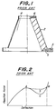
- a rubbery hollow cylindrical marine fender of a conical trapezoidal form as shown in Fig. 1.
- This marine fender comprises a main cylindrical rubber portion 2, a securing flange portion 3 for a quay wall, a shock receiving portion 4 and reinforcing steel plates 5, 6 embedded in the portions 3, 4.
- a deflection - reaction force curve absorbing a berthing energy as shown in Fig. 2.
- the reaction force increases with the increase of the deflection to arrive at an upper peak (point A), it decreases to arrive at a point C though the deflection increases, and again rapidly increases with further increase of the deflection.
- the marine fender exhibiting such a characteristic curve is actually used up to a point B showing the reaction force equal to the point A, in which the absorption energy of the marine fender is represented by an area surrounded by the deflection - reaction force curve and an abscissa up to the point B.
- the reaction force is actually decreased to the point C, so that the absorption energy is lost only by a portion S corresponding to an area surrounded by dotted line A-B and a curved line A-C-B. Therefore, it is demanded to raise the falling of reaction force represented by the point C to the dotted line A-B to increase the energy absorption by the area S.
- V-shaped marine fender subjected to a berthing load in a direction perpendicular to the axial direction thereof.
- This marine fender comprises a main cylindrical portion of a frustoconical form and a shock receiving portion of a cylindrical form, in which the loss of the absorption energy is attempted to be reduced by specifying relationships between height of the main cylindrical portion and height of the shock receiving portion and between outer diameter of the shock receiving portion and inner diameter of a base of the main cylindrical portion.
- a timing of contacting an outer surface of the buckled main cylindrical portion with a hull of the berthing vessel is delayed by mainly making the height of the shock receiving portion relatively high, whereby the energy absorbing quantity is increased.
- the shock receiving portion becomes higher, the deformation is necessarily caused in the shock receiving portion to create the same falling of the reaction force as in Fig. 2, so that it is not so better to use such a marine fender in view of the energy efficiency.
- an object of the invention to provide a rubbery buckling-type marine fender capable of reducing the loss of the absorption energy as far as possible.
- the invention is to provide a rubbery buckling-type marine fender capable of efficiently preventing the falling phenomenon of reaction force produced through the buckling deformation of the main rubber body portion of the conventional marine fender by rendering a region of the main rubber body portion adjacent or close to an inner buckling point thereof into a thickened region.
- a rubbery buckling-type marine fender comprising a main rubber body portion, a securing flange portion, and a shock receiving portion, in which an inner peripheral surface of the main rubber body portion is expanded inward in a region adjacent or close to a buckling point produced by buckling deformation of the main rubber body portion at at least one side with respect to the buckling point to form a rubber thickened region.
- the invention is based on results of actually observing the buckling deformation of the buckling-type marine fender such as cylindrical marine fender or the like in detail.
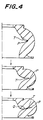
- the inner peripheral surface of the main rubber body portion corresponding to the region between the points P and Q is expanded inward to form a rubber thickened region T for filling in the uncontacted space between the points P and Q as shown in Fig. 4, whereby the contact compressed region of the main rubber body portion can positively be increased between the points P and Q of Fig. 4 to increase the reaction force between the points A and B of Fig. 2.
- the buckling deformation proceeds as shown by arrow in Fig.
- the inner peripheral surface regions of the main rubber body portion sandwiching the buckling point P gradually contact with each other to enlarge the contact compression area and hence the falling of the reaction force between the points A and B can be compensated by the compression reaction force owing to the presence of the rubber thickened region.
- the buckling point P is always held at a given position by the rubber thickened region formed on the inner peripheral surface of the main rubber body portion.
- the buckling point P is not specified in the conventional marine fender, so that the position of the buckling point P scatters every buckling deformation even in a lot of products or the same product and hence the scattering of the reaction force is caused. As seen from this fact, the scattering of the reaction force can be reduced by the formation of the rubber thickened region according to the invention.
- annular groove is formed on an outer surface of the main rubber body portion at a given position, whereby the main rubber body portion can efficiently be buckled in view of energy to improve the durability of the marine fender and to always provide a given reaction force. That is, the annular groove is formed on the outer surface of the main rubber body portion at a position somewhat separated from a reinforcing steel plate embedded in the securing flange portion, whereby the buckling is caused in the annular groove, so that the concentration of stress in the steel plate can be prevented to prevent the peeling of the steel plate from the adhesion surface to rubber and the rubber breakage to thereby improve the durability.
- a length L of the rubber thickened region is usually within a range of L ⁇ 0.5H because when it is too long, the displacement amount becomes small and the increase of the reaction force is prematurely caused.
- a thickness of the rubber thickened region may properly be selected in accordance with the size of the marine fender, length of the rubber thickened region, thickness of the main rubber body portion and the like.
- a first embodiment of the rubbery buckling-type marine fender according to the invention is a hollow cylindrical marine fender 10 of a frustoconical shape, which comprises a main rubber body portion 12, a securing flange portion 13 for a quay wall, and a shock receiving portion 14 for a vessel.
- a shock receiving plate (not shown) directly subjected to berthing of the vessel.
- the shock receiving portion 14 is reinforced with a steel plate 15 embedded therein, wherein an internal thread 16 is screwed in the steel plate 15, through which the shock receiving plate is secured to the shock receiving portion.
- the securing flange portion 13 is reinforced with a steel plate 17 embedded therein and also a bolt hole 18 is formed in the steel plate for fixing to a quay wall or the like through a bolt (not shown).
- a point P located in the inner peripheral surface of the main rubber body portion 12 is a buckling point when a load is applied to the shock receiving plate in the berthing of the vessel.
- the position h of the point P locates within a range of about 0.3H to 0.4H.
- the main rubber body portion 12 is largely bulged outward by starting from the buckling point P to cause the buckling, whereby the berthing load is absorbed.Z
- a rubber thickened region 19 is formed on an inner peripheral surface of the main rubber body portion 12 adjacent to the buckling point (at the side of the shock receiving portion in the illustrated embodiment).
- the dimensions of the marine fender are naturally different in accordance with the size of the vessel to be berthed.
- the height H of the marine fender 10 is 100 cm
- the main rubber body portion 12 has an outer diameter d1 of 90 cm, an inner diameter d2 of 6 0 cm and a diameter d3 (corresponding to the diameter of the shock receiving portion 14) of 80 cm, while the diameter D of the securing flange portion 13 is 130 cm.
- the thickness t of the main rubber body portion 12 is about 15 cm.
- the position h of the buckling point P is about 40 cm, while the rubber thickened region 19 has a length L of 23 cm and a thickness t1 of 3 cm.
- the marine fender 10 When the marine fender 10 is deformed by receiving the berthing load of the vessel or the like to cause the buckling deformation from the buckling point P, since the rubber thickened region 19 is arranged in the vicinity of the buckling point P, the inner peripheral surface parts of the main rubber body portion sandwiching the buckling point P contact with each other as shown in Fig. 4 to produce an effective reaction force. That is, the marine fender 10 according to the invention is small in the falling of the reaction force between the points A and B in the reaction force - deflection curve as shown in Fig. 2 because the reaction force changes in a substantially horizontal direction (broken line) between the points A and B, so that the loss of absorption energy can be prevented.
- the effect of increasing the absorption energy as mentioned above can sufficiently be developed when the marine fender satisfies conditions of 0.1H ⁇ t ⁇ 0.35H, 0.01t ⁇ t1 ⁇ 0.1H and L ⁇ 0.4H.
- annular grooves 20 and 21 are formed in the outer peripheral surface of the main rubber body portion 12 in the vicinities of the securing flange portion 13 and the shock receiving portion 14, respectively. These annular grooves 20 and 21 have a certain curvature. These annular grooves 20 and 21 serve as buckling points of the main rubber body portion 12 to prevent the peeling of the steel plates 15 and 17 from the adhesion surface to rubber and the rubber breakage.
- the rubber thickened region 19 is formed at one side of the inner peripheral surface of the main rubber body portion with respect to the buckling point P, but the rubber thickened region may be arranged at both sides sandwiching the buckling point P. Furthermore, the sectional shape of the rubber thickened region is not particularly restricted.
- Figs. 6 to 8 are modified embodiments of the rubbery buckling-type marine fender shown in Fig. 5, respectively.
- the rubber thickened region 19 has a square shape at the position corresponding to the buckling point P.
- the rubber thickened region 19 is formed at a side of the securing flange portion 13 with respect to the buckling point P.
- the rubber thickened regions 19-1 and 19-2 are formed at both sides with respect to the buckling point P.
- the annular grooves 20 and 21 are V-shaped in section.
- Figs. 9 to 11 are the other embodiments of the rubbery buckling-type marine fender according to the invention, respectively.
- the marine fender 30 of Fig. 9 is a cell-type marine fender comprising a main rubber body portion provided with two rubber thickened regions 19 sandwiching the buckling point P.
- the marine fender 40 of Fig. 10 is a V-shaped marine fender comprising a main rubber body portion provided with the rubber thickened region 19 at one side with respect to the buckling point P.
- the marine fender 50 of Fig. 11 is a V-shaped marine fender comprising a main rubber body portion provided with two rubber thickened regions 19 sandwiching the buckling point P.
- the uncontacted space formed between the buckling point P and the point Q in Fig. 3 is filled with the rubber thickened region formed in the inner peripheral surface of the main rubber body portion adjacent or close to the buckling point P, so that there are provided rubbery buckling-type marine fenders developing an excellent absorption performance against berthing shock without falling of the reaction force in the deflection - reaction force curve.
Landscapes
- Engineering & Computer Science (AREA)
- General Engineering & Computer Science (AREA)
- Mechanical Engineering (AREA)
- Ocean & Marine Engineering (AREA)
- Environmental & Geological Engineering (AREA)
- Civil Engineering (AREA)
- Structural Engineering (AREA)
- Health & Medical Sciences (AREA)
- Child & Adolescent Psychology (AREA)
- Chemical & Material Sciences (AREA)
- Combustion & Propulsion (AREA)
- Vibration Dampers (AREA)
- Body Structure For Vehicles (AREA)
Applications Claiming Priority (4)
| Application Number | Priority Date | Filing Date | Title |
|---|---|---|---|
| JP5095220A JPH06280237A (ja) | 1993-03-29 | 1993-03-29 | 防舷材 |
| JP95220/93 | 1993-03-29 | ||
| JP645170/94 | 1994-02-18 | ||
| JP6045170A JPH07229129A (ja) | 1994-02-18 | 1994-02-18 | ゴム製筒型防舷材 |
Publications (2)
| Publication Number | Publication Date |
|---|---|
| EP0622495A1 true EP0622495A1 (fr) | 1994-11-02 |
| EP0622495B1 EP0622495B1 (fr) | 1998-07-29 |
Family
ID=26385146
Family Applications (1)
| Application Number | Title | Priority Date | Filing Date |
|---|---|---|---|
| EP94302086A Expired - Lifetime EP0622495B1 (fr) | 1993-03-29 | 1994-03-23 | Défense marine |
Country Status (5)
| Country | Link |
|---|---|
| US (1) | US5458077A (fr) |
| EP (1) | EP0622495B1 (fr) |
| KR (1) | KR100309057B1 (fr) |
| CN (1) | CN1034647C (fr) |
| AU (1) | AU664794B2 (fr) |
Cited By (7)
| Publication number | Priority date | Publication date | Assignee | Title |
|---|---|---|---|---|
| WO1997001479A1 (fr) * | 1995-06-26 | 1997-01-16 | Lee Sang Choon | Defense |
| EP0812961A3 (fr) * | 1996-06-13 | 1998-05-20 | Bridgestone Corporation | Défense marine caoutchouteuse |
| US6572307B2 (en) | 1999-12-20 | 2003-06-03 | Sumitomo Rubber Industries, Ltd. | Fender with step and/or projection |
| WO2003056106A1 (fr) * | 2001-12-26 | 2003-07-10 | Shibata Industrial Co., Ltd. | Defense |
| AU2005200291B2 (en) * | 1999-12-20 | 2006-09-28 | Sumitomo Rubber Industries, Ltd. | Fender |
| WO2006125277A1 (fr) * | 2005-05-27 | 2006-11-30 | Harbour & Marine Engineering Pty Ltd | Systeme de controle de defense |
| DE102010053907A1 (de) | 2010-12-09 | 2012-06-14 | Gerhard Meissner | Starre stoßfeste Fendertafel und Fender mit einer solchen Fendertafel |
Families Citing this family (13)
| Publication number | Priority date | Publication date | Assignee | Title |
|---|---|---|---|---|
| US5791637A (en) * | 1996-01-11 | 1998-08-11 | Iso Dynamics, Inc. | Energy absorbing compression spring body and method of making the same |
| US6053664A (en) * | 1997-03-03 | 2000-04-25 | The United States Of America As Represented By The Secretary Of The Navy | Elastomeric composite bumper system and method for absorbing high energy impact |
| SE520131C2 (sv) * | 2000-04-25 | 2003-05-27 | Sumitomo Rubber Ind | Fender samt framställning av densamma |
| US6604735B2 (en) * | 2000-12-22 | 2003-08-12 | Lockheed Martin Corporation | Elastomer variants |
| US6701860B2 (en) | 2001-10-01 | 2004-03-09 | Metso Minerals (Trelleborg) Ab | Fender |
| SE520216C2 (sv) * | 2001-10-01 | 2003-06-10 | Metso Minerals Trelleborg Ab | Fender |
| NL1028679C2 (nl) * | 2005-04-01 | 2006-10-09 | Orca V O F | Schip met van vervormingsopnemers voorziene vloeistoftransporttanks. |
| US8061698B2 (en) * | 2006-07-27 | 2011-11-22 | Chemtura Corporation | Geometric shaped side bearing pad |
| US8992129B2 (en) * | 2011-02-08 | 2015-03-31 | Bridgestone Corporation | Marine fender |
| CN102995606B (zh) * | 2012-12-11 | 2015-04-29 | 烟台泰鸿橡胶有限公司 | 充填式转鼓护舷及其制备方法 |
| SE539552C2 (en) * | 2015-01-26 | 2017-10-10 | Ab Halmstads Gummifabrik | Fender system |
| JP6740952B2 (ja) * | 2017-04-12 | 2020-08-19 | 住友ゴム工業株式会社 | 防舷装置 |
| CN117966998A (zh) * | 2024-04-02 | 2024-05-03 | 洛阳双瑞橡塑科技有限公司 | 一种抗冲击防护地板 |
Citations (4)
| Publication number | Priority date | Publication date | Assignee | Title |
|---|---|---|---|---|
| GB1197534A (en) * | 1967-11-02 | 1970-07-08 | Bridgestone Tire Kabushiki Kti | Marine Fender |
| FR2441683A1 (fr) * | 1978-11-13 | 1980-06-13 | Bridgestone Tire Co Ltd | Pare-chocs marins creux en matiere caoutchoutee elastique |
| EP0092893A1 (fr) * | 1982-04-28 | 1983-11-02 | Bridgestone Tire Company Limited | Pare-choc marin |
| EP0135997A2 (fr) * | 1983-08-22 | 1985-04-03 | Bridgestone Corporation | Amortisseur marin |
Family Cites Families (6)
| Publication number | Priority date | Publication date | Assignee | Title |
|---|---|---|---|---|
| DE2104212A1 (de) * | 1971-01-29 | 1972-08-03 | Clouth Gummiwerke Ag | Puffer oder Fender |
| FR2238091B1 (fr) * | 1973-07-18 | 1976-07-23 | Kleber Colombes | |
| JPS5952243B2 (ja) * | 1977-04-28 | 1984-12-19 | 株式会社ブリヂストン | 防げん材 |
| JPS5470592A (en) * | 1977-11-17 | 1979-06-06 | Bridgestone Corp | Fender |
| JPS58145321U (ja) * | 1982-03-20 | 1983-09-30 | 住友ゴム工業株式会社 | ゴム製筒形防舷材 |
| JPS6055111A (ja) * | 1983-09-05 | 1985-03-30 | Bridgestone Corp | 防舷材 |
-
1994
- 1994-03-18 AU AU57868/94A patent/AU664794B2/en not_active Ceased
- 1994-03-23 EP EP94302086A patent/EP0622495B1/fr not_active Expired - Lifetime
- 1994-03-28 US US08/218,176 patent/US5458077A/en not_active Expired - Lifetime
- 1994-03-28 KR KR1019940006288A patent/KR100309057B1/ko not_active Expired - Lifetime
- 1994-03-29 CN CN94103765A patent/CN1034647C/zh not_active Expired - Fee Related
Patent Citations (4)
| Publication number | Priority date | Publication date | Assignee | Title |
|---|---|---|---|---|
| GB1197534A (en) * | 1967-11-02 | 1970-07-08 | Bridgestone Tire Kabushiki Kti | Marine Fender |
| FR2441683A1 (fr) * | 1978-11-13 | 1980-06-13 | Bridgestone Tire Co Ltd | Pare-chocs marins creux en matiere caoutchoutee elastique |
| EP0092893A1 (fr) * | 1982-04-28 | 1983-11-02 | Bridgestone Tire Company Limited | Pare-choc marin |
| EP0135997A2 (fr) * | 1983-08-22 | 1985-04-03 | Bridgestone Corporation | Amortisseur marin |
Cited By (9)
| Publication number | Priority date | Publication date | Assignee | Title |
|---|---|---|---|---|
| WO1997001479A1 (fr) * | 1995-06-26 | 1997-01-16 | Lee Sang Choon | Defense |
| EP0812961A3 (fr) * | 1996-06-13 | 1998-05-20 | Bridgestone Corporation | Défense marine caoutchouteuse |
| US5975000A (en) * | 1996-06-13 | 1999-11-02 | Bridgestone Corporation | Rubbery marine fenders |
| US6572307B2 (en) | 1999-12-20 | 2003-06-03 | Sumitomo Rubber Industries, Ltd. | Fender with step and/or projection |
| SG96592A1 (en) * | 1999-12-20 | 2003-06-16 | Sumitomo Rubber Ind | Fender |
| AU2005200291B2 (en) * | 1999-12-20 | 2006-09-28 | Sumitomo Rubber Industries, Ltd. | Fender |
| WO2003056106A1 (fr) * | 2001-12-26 | 2003-07-10 | Shibata Industrial Co., Ltd. | Defense |
| WO2006125277A1 (fr) * | 2005-05-27 | 2006-11-30 | Harbour & Marine Engineering Pty Ltd | Systeme de controle de defense |
| DE102010053907A1 (de) | 2010-12-09 | 2012-06-14 | Gerhard Meissner | Starre stoßfeste Fendertafel und Fender mit einer solchen Fendertafel |
Also Published As
| Publication number | Publication date |
|---|---|
| AU664794B2 (en) | 1995-11-30 |
| CN1034647C (zh) | 1997-04-23 |
| EP0622495B1 (fr) | 1998-07-29 |
| US5458077A (en) | 1995-10-17 |
| CN1103371A (zh) | 1995-06-07 |
| AU5786894A (en) | 1994-10-27 |
| KR100309057B1 (ko) | 2001-12-15 |
| KR940021357A (ko) | 1994-10-17 |
Similar Documents
| Publication | Publication Date | Title |
|---|---|---|
| US5458077A (en) | Marine fenders | |
| US5975000A (en) | Rubbery marine fenders | |
| US4355792A (en) | Hollow marine fender | |
| US4277055A (en) | Cushioning fender | |
| US4601611A (en) | Marine fender | |
| US4515502A (en) | Marine fenders | |
| US6572307B2 (en) | Fender with step and/or projection | |
| US5018641A (en) | End construction with hollow beam construction for a drum | |
| US4721414A (en) | Marine fenders | |
| US8408413B2 (en) | Pallet container | |
| JPH07229129A (ja) | ゴム製筒型防舷材 | |
| JP4190816B2 (ja) | 防舷材 | |
| JP2775388B2 (ja) | 防舷材 | |
| JPH0649826A (ja) | 防舷材 | |
| JPS6319279Y2 (fr) | ||
| JPH08326815A (ja) | 衝撃荷重の吸収構造 | |
| JP2006207680A (ja) | 積層ゴム支承体 | |
| JPH0874225A (ja) | 防舷材 | |
| JPS6117618A (ja) | 防舷材 | |
| JPS6220488Y2 (fr) | ||
| JPH041129B2 (fr) | ||
| JP3308202B2 (ja) | 防舷装置 | |
| JPH06280237A (ja) | 防舷材 | |
| JP2001172940A (ja) | 防舷材 | |
| JP2018178520A (ja) | 防舷装置 |
Legal Events
| Date | Code | Title | Description |
|---|---|---|---|
| PUAI | Public reference made under article 153(3) epc to a published international application that has entered the european phase |
Free format text: ORIGINAL CODE: 0009012 |
|
| AK | Designated contracting states |
Kind code of ref document: A1 Designated state(s): GB NL SE |
|
| 17P | Request for examination filed |
Effective date: 19950427 |
|
| 17Q | First examination report despatched |
Effective date: 19961024 |
|
| GRAG | Despatch of communication of intention to grant |
Free format text: ORIGINAL CODE: EPIDOS AGRA |
|
| GRAG | Despatch of communication of intention to grant |
Free format text: ORIGINAL CODE: EPIDOS AGRA |
|
| GRAH | Despatch of communication of intention to grant a patent |
Free format text: ORIGINAL CODE: EPIDOS IGRA |
|
| GRAH | Despatch of communication of intention to grant a patent |
Free format text: ORIGINAL CODE: EPIDOS IGRA |
|
| GRAA | (expected) grant |
Free format text: ORIGINAL CODE: 0009210 |
|
| AK | Designated contracting states |
Kind code of ref document: B1 Designated state(s): GB NL SE |
|
| PLBE | No opposition filed within time limit |
Free format text: ORIGINAL CODE: 0009261 |
|
| STAA | Information on the status of an ep patent application or granted ep patent |
Free format text: STATUS: NO OPPOSITION FILED WITHIN TIME LIMIT |
|
| 26N | No opposition filed | ||
| REG | Reference to a national code |
Ref country code: GB Ref legal event code: IF02 |
|
| PGFP | Annual fee paid to national office [announced via postgrant information from national office to epo] |
Ref country code: GB Payment date: 20030319 Year of fee payment: 10 |
|
| PGFP | Annual fee paid to national office [announced via postgrant information from national office to epo] |
Ref country code: NL Payment date: 20030327 Year of fee payment: 10 |
|
| PG25 | Lapsed in a contracting state [announced via postgrant information from national office to epo] |
Ref country code: GB Free format text: LAPSE BECAUSE OF NON-PAYMENT OF DUE FEES Effective date: 20040323 |
|
| PG25 | Lapsed in a contracting state [announced via postgrant information from national office to epo] |
Ref country code: NL Free format text: LAPSE BECAUSE OF NON-PAYMENT OF DUE FEES Effective date: 20041001 |
|
| GBPC | Gb: european patent ceased through non-payment of renewal fee |
Effective date: 20040323 |
|
| NLV4 | Nl: lapsed or anulled due to non-payment of the annual fee |
Effective date: 20041001 |
|
| PGFP | Annual fee paid to national office [announced via postgrant information from national office to epo] |
Ref country code: SE Payment date: 20130312 Year of fee payment: 20 |
|
| REG | Reference to a national code |
Ref country code: SE Ref legal event code: EUG |