EP0622677A2 - Entwicklungsgerät - Google Patents
Entwicklungsgerät Download PDFInfo
- Publication number
- EP0622677A2 EP0622677A2 EP94201120A EP94201120A EP0622677A2 EP 0622677 A2 EP0622677 A2 EP 0622677A2 EP 94201120 A EP94201120 A EP 94201120A EP 94201120 A EP94201120 A EP 94201120A EP 0622677 A2 EP0622677 A2 EP 0622677A2
- Authority
- EP
- European Patent Office
- Prior art keywords
- rollers
- wall structure
- roller
- structure according
- opening
- Prior art date
- Legal status (The legal status is an assumption and is not a legal conclusion. Google has not performed a legal analysis and makes no representation as to the accuracy of the status listed.)
- Granted
Links
Images




Classifications
-
- G—PHYSICS
- G03—PHOTOGRAPHY; CINEMATOGRAPHY; ANALOGOUS TECHNIQUES USING WAVES OTHER THAN OPTICAL WAVES; ELECTROGRAPHY; HOLOGRAPHY
- G03D—APPARATUS FOR PROCESSING EXPOSED PHOTOGRAPHIC MATERIALS; ACCESSORIES THEREFOR
- G03D3/00—Liquid processing apparatus involving immersion; Washing apparatus involving immersion
- G03D3/08—Liquid processing apparatus involving immersion; Washing apparatus involving immersion having progressive mechanical movement of exposed material
- G03D3/13—Liquid processing apparatus involving immersion; Washing apparatus involving immersion having progressive mechanical movement of exposed material for long films or prints in the shape of strips, e.g. fed by roller assembly
- G03D3/132—Liquid processing apparatus involving immersion; Washing apparatus involving immersion having progressive mechanical movement of exposed material for long films or prints in the shape of strips, e.g. fed by roller assembly fed by roller assembly
Definitions
- the present invention relates to processing apparatus and is more particularly concerned with such apparatus which include through-wall structures for separating processing chambers within the apparatus.
- a sheet of photosensitive material typically undergoes a number of sequential processing steps; that is, at least one developing step, one fixing step, and a washing operation.
- the photosensitive material is brought into contact with a processing liquid (developer, fixer solution, and so forth) to produce a desired chemical interaction with the film substrate or to wash chemical residue away from the substrate surface.
- a processing liquid developer, fixer solution, and so forth
- processors of the prior art a sheet of photosensitive material is passed through a series of open topped containers, each containing a quantity of processing fluid, by a series of rollers over a generally sinusoidal transport path into and out of each open topped container.
- a typical processor of this kind is shown in US-A-4 994 837.
- the photosensitive material is more susceptible to scratching or marring due to the stresses induced as the material remains in substantial contact with the multiple sets of rollers which are required to traverse a serpentine transport path in a processor of this type.
- processors of this type photosensitive material enters a chamber partially full of a processing liquid through an opening in the chamber wall, the opening being above the level of the processing liquid which is contained therein. The material is then brought into contact with the processing fluid by either pumping additional processing material into the chamber, thereby raising the level of liquid present in the chamber to contact the passing web, or by downwardly conveying the material to the level of processing liquid. Examples of processors of this type are disclosed in US-A- 4 023 190 and US-A-4 142 194.
- Processors using methods such as those taught by the preceding examples require exposing the photosensitive material to atmospheric conditions for extended periods, prior to immersion into a processing solution, thereby also affecting the throughput of a processing apparatus.
- US-A-4 987 438 discloses a processor in which a continuous sheet of photosensitive material passes directly through an integrated wall structure positioned to separate adjacent closed containers which are filled with a processing fluid, the wall structure having a pair of parallel, contacting rollers which are rotatably driven and disposed therein.
- the wall structure is sized to receive the web of photosensitive material, and the rollers act as a transport means for moving the web from and through one processing station to the next adjacent station.
- a processing apparatus having a through-wall structure as described provides a means for the photosensitive material to traverse a direct transport path by way of rollers already incorporated within the wall structure, without the need for additional rollers or other transport means.
- the processors described require a rather complex sealing means, particularly at the interface where the roller end(s) are attached to either the chamber sidewall or the sidewall of the through-wall structure.
- a rather complex sealing means particularly at the interface where the roller end(s) are attached to either the chamber sidewall or the sidewall of the through-wall structure.
- To provide an effective seal at this interface is relatively difficult because the rollers must be allowed to rotate to allow the web of photosensitive material to pass therethrough, while also preventing the passage through the ends of processing liquid between adjacent chambers.
- roller ends In order to prevent significant leakage of processing liquid between adjacent chambers separated by a through-wall structure as described requires that either the roller ends be very tightly manufactured (that is, toleranced on the order of thousandths of an inch) to adequately match the roller ends to the sidewall, or that gasketing or other sealing material be used between the sidewall and the roller end.
- a wall structure for use in processing apparatus for processing photosensitive material, the apparatus having at least one chamber for containing a processing fluid, the wall structure forming a portion of at least one chamber and allowing the photosensitive material to pass therethrough, the wall structure comprising:- a top surface; a bottom surface; a pair of side surfaces defining a first opening; and at least one pair of substantially parallel contacting rollers having respective longitudinal axes, the roller pair being positioned in the first opening so that each longitudinal axis is aligned with centerline of the wall structure, the combined outer diameters of the roller pair being slightly greater than the first opening when the rollers are not positioned in the wall structure; characterized in that the rollers are radially deformable so as to fit within the first opening, the side surfaces each having a recessed portion for receiving respective ends of the rollers, each recessed portion defining a second opening which is slightly smaller than the outer diameter of the roller ends.
- apparatus for processing photosensitive material comprising:- a plurality of processing chambers each containing processing fluid, and at least one internal wall structure as described above.
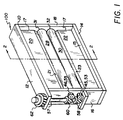
- a wall structure 100 is provided, made up of a support frame 10, comprising a top and bottom support 12, 14 respectively, and a pair of sidewalls 16 and 18, which are assembled together using threaded fasteners, (not shown), though other known mounting means can be used.
- Support frame 10 is made preferably from a light-weight thermoplastic material.
- support frame 10 is made of Acrylonitrile-Butadiene-Styrene polymer (commonly referred to as ABS), although other suitable materials which are non-reactive in the presence of processing fluid may also be used.
- Upper wall member 20 is mounted to the lower surface 13 of top support 12.
- lower wall member 22 is mounted to the upper surface 15 of bottom support 14.
- the ends 17 of each wall member 20, 22 are fastened to the interior side of sidewalls 16, 18 by known means to provide sealed surfaces at their respective interfaces.
- wall members 20, 22 are each tapered at their lower and upper ends, 21, 23, respectively, to form rounded wiping surfaces 24, 26.
- Wall members 20, 22 can be provided having a variety of configurations to provide an adequate internal wall structure.
- a wall structure 100A is provided wherein wall members 20A, 22A are slightly tapered and substantially flat wiping surfaces 24A, 26A are inset at ends 21A, 23A, rather than providing rounded ends for providing contact with a pair of rollers 28A, 30A inserted therebetween as discussed below.
- wall members 20A, 22A need not be identical, according to Figure 2B.
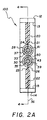
- Each roller 28, 30 comprises a rigid inner core 33, 35 extending over length L, Figure 4, which is covered over substantially most of its length L1, Figure 4, by a sublayer 37, 39, made of a compliant/resilient material.
- An outer layer 41, 43 made of a material having a low coefficient of friction covers compliant sublayer 37, 39.
- rollers 28, 30 are identical in this embodiment, each having steel inner cores 33, 35 having a diameter D of 2.54cm (1.00in), a silicone rubber sublayer 37, 39 having a uniform thickness T of 0.64cm (0.250in) and a substantially uniform outer layer 41, 43 made from PFA, a form of tetrafluoroethylene (Teflon TM) and having a thickness T1 of 0.012cm (0.005in).
- the silicone rubber sublayer 37, 39 preferably has a Shore A hardness of 20A, though other compliant materials having a Shore A hardness of 20A to 40A have been found to be acceptable for the present embodiment.
- the coefficient of friction of outer layer 41, 43 is 0.10, though this coefficient can be varied.
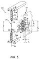
- rollers 28, 30 have the same outer diameter, D1.
- opening 34 is approximately 0.076cm (0.030in) smaller than the combined unstressed outer diameters D2 of rollers 28, 30. Providing the size of opening 34 smaller than the combined outer diameters D2 of the rollers 28, 30 produces an interference fit. This interference fit is produced between the nip 50 of the rollers 28, 30, as well as between the individual rollers 28, 30 and adjacent wiping surfaces 24, 26 when rollers 28, 30 are inserted into longitudinal opening 34, as shown in Figure 2A. The interference fit provides a seal between the rollers and wiping surfaces at each interface.
- rollers 28, 30 are positioned within longitudinal opening 34 so that roller central axes 31, 32 are substantially parallel.
- Central axes 31 and 32 form a plane 44, Figure 3, which is preferably arranged coincident to the centerline 36 of wall structure 100.
- an interference of 0.254cm (0.010in) per interface between the rollers 28, 30 and the opening 34 is useful in this embodiment, the exact amount of interference created between opening 34 and the outer diameters of rollers 28, 30 may be varied to accommodate the material of the rollers.
- An amount of interference is provided so as to produce an effective seal whcih will prevent significant quantities of liquid from migrating through wall structure 100. Additional interference must be provided to compensate for any manufacturing tolerance buildups to ensure a nominal interference is achieved.
- core shaft end sections 45, 46 extend through clearance holes (not shown) provided in sidewall 16.
- Mounted to end sections 45, 46 are left and right hand helical gears 53, 55 respectively, which mate with matching worm gears 58, 60, Figure 1, mounted to drive shaft 57, vertically extending along the exterior side of sidewall 16.
- Additional drive gearing 62, provided at the upper end of drive shaft 57, and positioned along top support 12 is engagable with a second drive means.
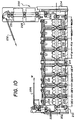
- An example of a second drive means is partially shown in Figure 10.
- Other conventional driving means may be utilized to drive the rollers 28, 30 and are not considered a part of the present invention.
- rollers 28, 30 The low frictional coefficient of outer roller surfaces 41, 43 allow rollers 28, 30 to be easily rotated, in spite of the interference fit of the rollers 28, 30 into opening 34.
- Drive means are only required at one end of the rollers 28, 30.
- the remaining shaft end sections 47, 48 preferably extend into clearance holes (not shown) extending through sidewall 18 to allow for easier roller access.
- sidewall 16 is provided with a recessed portion 64 shaped so as to receive roller ends 66, 68.
- Recessed portion 64 is preferably defined by two overlapping and substantially circular sections 70, 72, each defined by a diameter D3, and by interior sidewalls 78, 80, respectively, which extend somewhat circumferentially along the interior of sidewall 16.
- Each circular section 70, 72 is also defined by a central axis 74, 76, respectively, which is coincident with the position of central axes 31, 32, Figure 3, of rollers 28, 30, and preferably coplanar with roller plane 44 when rollers 28, 30 are positioned within longitudinal opening 34.
- Diameter D3 is slightly smaller than the outer diameter D1 of a corresponding roller end 66, 68, the outer roller diameter D1, Figure 3, being measured in an uncompressed state.
- This undersizing of each circular opening 70, 72 provides an interference fit between the rollers 28, 30 and sidewall 16 when the roller ends 66, 68 are inserted into recess 64.
- Circular sections 70, 72 terminate at back surfaces 82, 84 which define the rear portions of recess 64.
- a similar recess (not shown) is provided in sidewall 18 to accommodate roller ends 67, 69 of rollers 28, 30 respectively.
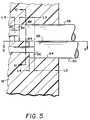
- Each roller end 66, 68 is partially, but not fully engaged into recess 64, creating gaps 94, 96 between the roller ends 66, 68 and back surfaces 82, 84 respectively. Similar gaps 95, 97 are provided between roller ends 67, 69 and back surfaces 83, 85, respectively.
- each gap provides sufficient margin for longitudinal roller misalignment, and minimizes or avoids premature wearability of the roller ends 66, 68 against the back surfaces 82, 84.
- Providing gaps 94, 96 between the roller ends and the back surfaces of each sidewall 16, 18 also allows each roller 28, 30 to "float" in a longitudinal direction along central axes 31, 32.
- each gap is approximately 0.157cm (0.062in) in depth, though this distance can be varied.
- recessed portion 64 is preferably defined as a single opening, having a substantially figure-of-eight configuration over the distance L2 in which roller ends 66, 68 equally extend into sidewall 16.
- roller end 66 is inset an additional distance L3 into sidewall 16. Because a tight circumferential seal is provided between outer surface 41 and the interior surface 78 of circular section 70, Figure 6, over this distance, there is no leakage into gap 94.
- roller end 68 extends a distance L2 of 0.63cm (0.25in), and roller end 66 extends an additional distance L2 + L3 of 1.27cm (0.50in) into sidewall 16.
- L2 0.63cm (0.25in
- roller end 66 extends an additional distance L2 + L3 of 1.27cm (0.50in) into sidewall 16.
- the longitudinal offsetting of roller ends 67, 69 into sidewall 18 is similar, but roller ends 67, 69 are preferably oppositely staggered. This arrangement allows the use of identical rollers which simplifies replacement and maintenance of rollers.
- protrusions 86, 88 which define the preferred figure eight configuration of recess 64.
- Protrusions 86, 88 each extend to form two rounded edges 87, 89 which are adjacent the nip 50 of the rollers 28, 30 when rollers 28,30 are inserted into recess 64, as shown most clearly in Figure 7.
- edges 87, 89 could be made to conform more closely to the nip 50 to provide a more complete circumferential seal, it is preferable that edges 87, 89 be rounded because a sharpened corner could more easily tear a roller surface.
- the effect of rounding the edges 87, 89 is that two small openings 90 and 92 adjacent nip 50 are formed.
- roller sublayers 37, 39 allow each roller end 66, 68 to be radially compressed to accommodate the roller ends within recess 64.
- the effect of the interference fit is that fluid seals are formed between the outer surfaces 41, 43 of rollers 28, 30 and adjacent interior sidewalls 78, 80, respectively as well as between the outer surfaces 41, 43 of the rollers 28, 30 which are in contact at the nip 50. Similar seals (not shown) are provided at sidewall 18. Further, outer layer 41, 43 assists the roller ends to be easily rotated even though compressive forces are created due to the interference fit.
- roller ends 66, 68 and recess 64 can be varied, provided that a nominal amount of interference is provided for.
- the 0.254cm (0.010 in) interference between recess 64 and rollers 28, 30 has been found to provide the desired sealing while still allowing the structure to be manufactured and assembled at a relatively low cost.
- the compliant nature of sublayer 37, 39 coupled with the wear resistance and low coefficient of friction of outer layer 41, 43 produce an effective liquid seal without exact dimensioning or tolerancing of the component parts of previously known wall structures.
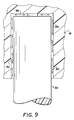
- openings 90, 92 are substantially triangularly-shaped channels, disposed on either side of the nip 50 of rollers 28, 30, which extend inwardly into sidewall 16 and terminate at gap 96. Because of the longitudinal offsetting of roller end 66 relative to roller end 68, a seal is provided over the entirety of circular opening 70 over the distance L4 ( Figure 5) which roller end 66 additionally extends into sidewall 16. This is shown most clearly in Figure 9.
- channels 90, 92 provide a potential leak path indicated by arrows 99 by which processing liquid (not shown) could possibly migrate through wall structure 100.
- a processing liquid (not shown) can enter sidewall 16 through either channel 90 or 92, flow around the roller end 66 through gap 96 and exit through the remaining channel 92 or 90 thereby migrating through wall structure 100.
- the potential leak path represented is relatively small, however, in that each channel 90, 92 is defined by a substantially triangular opening having dimensions of approximately 0.038cm x 0.076cm x 0.635cm (0.015in x 0.03in x 0.25in).
- the potential leak path 99 can optionally be lengthened by increasing this distance, thereby further minimizing the amount of potential leakage through wall structure 100.
- a washer such as made from a closed cell foam or other light weight material or other gasketing material can be positioned within gap 96 to block the small quantity of liquid which could enter from either channel 90 or 92.
- a similar arrangement (not shown) can be provided within sidewall 18.
- the present invention can be described in the embodiment shown in Figure 8 wherein a wall structure 100, as described above, divides adjacent chambers 110, 120, each adjacent chamber being filled with a processing fluid 130, 140 respectively.
- a continuous web W of photosensitive material is introduced between parallel contacting rollers 28, 30 though individual sheets of material can also be suitably introduced using the described wall structure.
- the rollers being driven by left and right hand gear trains, see Figures 1 and 3, cooperate to permit rollers 28, 30 to act as a web transport means.
- roller 28 is rotating in a counterclockwise direction and roller 30 is driven to rotate in a clockwise direction so as to provide a transport direction from chamber 110 toward chamber 120 as shown in Figure 8.
- rollers 28, 30, can be varied for processing apparatus having any known processing path.
- the web W having a typical thickness of 0.018cm (0.007in) in the embodiment illustrated, is allowed to pass between rollers 28, 30 at nip 50 to be taken up and horizontally transported into chamber 120 due to the compliancy of sublayers 37, 39 which radially deform in the presence of the introduced web. This further compresses the rollers 28, 30, but because the compliant sublayers 37, 39 ( Figure 2A) absorb the additional compressive forces which are created there is no substantial increase in drive torque required to rotate the rollers 28, 30.
- the low coefficient of friction of outer layer 41, 43 ( Figure 2A) allows the photosensitive web to easily pass through nip 50 per arrow 102 with a reduced chance of the web adhering to the rollers or premature stretching or tearing of the web.
- the compressive forces created provide an effective seal at nip 50 between contacting rollers 28, 30, while the low coefficient of friction of outer layer 41, 43 assists the rollers 28, 30 so that they can be easily rotated despite the action of the compressive forces, represented by arrows 108, 111. This minimizes significant quantities of processing liquid 130 from passing between rollers 28, 30 and into adjacent chamber 120.
- rollers 28, 30 provide a similar seal between the individual rollers 28, 30 and adjacent wiping surfaces 24, 26.
- processing liquid 140 present in chamber 120 and carried by the rotation of rollers 28, 30 is squeegeed from the outer roller surfaces 41, 43 ( Figure 2A) by wiping surfaces 24, 26 due to compressive contact with rollers 28, 30 respectively, thereby preventing significant migration of liquid into processing chamber 110.
- the compressive forces created due to the interference fit are indicated by arrows 112 and 114.
- Other contact means between rollers 28, 30 and upper and lower wall sections 20, 22 can be provided, though in the preferred embodiment illustrated wiping surfaces 24, 26 provide a single point of contact which produces a minimal amount of roller wear.
- each roller end-sidewall interface processing liquid 130 is prevented from substantially migrating through wall structure 100 and into chamber 120 by the placement of roller ends 66, 68 and 67, 69 into sidewalls 16, 18 respectively.
- roller ends 66, 68 and 67, 69 into sidewalls 16, 18 respectively.
- an interference fit is created between the outer surfaces 41, 43 of each roller end 66, 68 and sidewall 16, placing the interior sidewalls 78, 80 of the recessed portion 64 and the outer surfaces 41, 43 of roller ends 66, 68 into compressive contact.
- the creation of the compressive contact provides seals along those surfaces brought into contact as well as at the nip 50 of roller ends 66, 68. This is most clearly seen in Figure 5.
- processor 200 consists of an elongated housing 201, divided by suitable partitions to define a web entrance chamber 202, a series of developing chambers 206, 208, 210 and 212, a rinse chamber 214, a series of fixing chambers 216 and 218, a series of wash chambers 220 and 222, a web exit chamber 224 and a final drying module 225.
- the web W is fed into the apparatus 200 by an entrance chute 226 and transported through entrance chamber 202 and through each chamber by means of transport rollers 228.
- the web is transported from the final wash chamber 222 to the drying module 225 by transport rollers 230 from which it is exited by additional rollers 231 and chute 232.
- some or all of the chambers 206, 208, 210, 212 and 216, 218, 220, 222 may contain a web processing module 234. It can be seen, however, that the present invention can be used in conjunction with modules 234 or other means of applying processing liquid to a web passing through a chamber.
- Each processing chamber 206, 208, 210, 212 and 216, 218, 220, 222 is separated by a wall structure 100 as described above and referred to in Figures 1 to 9.
- Wall structures 100 provide a means of horizontally transporting the web of photosensitive material between adjacent chambers which can be filled with a processing liquid, while also providing an effective sealing means to prevent cross-contamination between the chambers.
- each wall structure 100 can be independently removed and positioned within processor 200 to provide for a number of possible processing arrays by which the size and number of processing chambers can be varied.
- the effect of the modularity and indexing features described by this reference is that the apparatus 200 becomes more versatile such that differing photosensitive materials can be processed using the same piece of apparatus.
Landscapes
- Physics & Mathematics (AREA)
- General Physics & Mathematics (AREA)
- Photographic Processing Devices Using Wet Methods (AREA)
- Delivering By Means Of Belts And Rollers (AREA)
Applications Claiming Priority (2)
| Application Number | Priority Date | Filing Date | Title |
|---|---|---|---|
| US54487 | 1993-04-27 | ||
| US08/054,487 US5313242A (en) | 1993-04-27 | 1993-04-27 | Thru-wall web processing apparatus |
Publications (3)
| Publication Number | Publication Date |
|---|---|
| EP0622677A2 true EP0622677A2 (de) | 1994-11-02 |
| EP0622677A3 EP0622677A3 (de) | 1995-05-10 |
| EP0622677B1 EP0622677B1 (de) | 1998-09-23 |
Family
ID=21991427
Family Applications (1)
| Application Number | Title | Priority Date | Filing Date |
|---|---|---|---|
| EP94201120A Expired - Lifetime EP0622677B1 (de) | 1993-04-27 | 1994-04-23 | Entwicklungsgerät |
Country Status (5)
| Country | Link |
|---|---|
| US (1) | US5313242A (de) |
| EP (1) | EP0622677B1 (de) |
| JP (1) | JPH06324459A (de) |
| CA (1) | CA2115338A1 (de) |
| DE (1) | DE69413447T2 (de) |
Cited By (2)
| Publication number | Priority date | Publication date | Assignee | Title |
|---|---|---|---|---|
| EP0789276A1 (de) * | 1996-02-08 | 1997-08-13 | Agfa-Gevaert N.V. | Vorrichtung zur Behandlung von fotographischen Blattmaterial |
| US6063571A (en) * | 1996-09-13 | 2000-05-16 | Hoechst Aktiengesellschaft | Process for amplifying nucleic acids using DNA/PNA primers |
Families Citing this family (9)
| Publication number | Priority date | Publication date | Assignee | Title |
|---|---|---|---|---|
| EP0744658A1 (de) * | 1995-05-20 | 1996-11-27 | Agfa-Gevaert N.V. | Gerät zum Entwickeln eines fotographischen Blattmaterials mittels Flüssigkeit |
| EP0744657A1 (de) * | 1995-05-20 | 1996-11-27 | Agfa-Gevaert N.V. | Gerät zur Entwicklung eines fotografischen Blattmaterials mittels Flüssigkeit |
| EP0769719A1 (de) * | 1995-10-17 | 1997-04-23 | Agfa-Gevaert N.V. | Apparat zur Nassbehandlung von photographischem Blattmaterial |
| EP0779547A1 (de) * | 1995-12-13 | 1997-06-18 | Agfa-Gevaert N.V. | Gerät zur Nassbehandlung von fotographischem blattförmigem Material |
| EP0779548A1 (de) * | 1995-12-13 | 1997-06-18 | Agfa-Gevaert N.V. | Gerät zur Nassbehandlung von Folienmaterial |
| EP0866370B1 (de) * | 1997-03-21 | 2003-07-02 | Agfa-Gevaert | Rolle zur Verwendung in Nassbehandlungsgerät |
| EP0896251A1 (de) * | 1997-07-28 | 1999-02-10 | Agfa-Gevaert N.V. | Verfahren zur Herstellung einer Litho-Druckplatte |
| EP0918253A1 (de) * | 1997-11-21 | 1999-05-26 | Agfa-Gevaert N.V. | Dichtungsanordnung |
| JP2005031199A (ja) * | 2003-07-08 | 2005-02-03 | Fuji Photo Film Co Ltd | 感光材料現像処理装置 |
Family Cites Families (34)
| Publication number | Priority date | Publication date | Assignee | Title |
|---|---|---|---|---|
| US3120795A (en) * | 1957-03-21 | 1964-02-11 | Polaroid Corp | Photographic products |
| US2918069A (en) * | 1958-01-15 | 1959-12-22 | Hanson Van Winkle Munning Co | Sealing rolls for tanks |
| US3057282A (en) * | 1959-04-06 | 1962-10-09 | Eastman Kodak Co | Fluid treating device for sheet or strip materials |
| US3277810A (en) * | 1964-04-22 | 1966-10-11 | Seymour L Hersh | Linear photographic processing system |
| US3662660A (en) * | 1970-08-05 | 1972-05-16 | Ronald P Layne | Apparatus for processing sensitized material |
| US3857040A (en) * | 1972-01-27 | 1974-12-24 | E Zwettler | Automatic film processing machine |
| US4023190A (en) * | 1975-06-02 | 1977-05-10 | Sybron Corporation | Film processor |
| DE2702335C3 (de) * | 1976-02-09 | 1984-06-07 | E.I. Du Pont De Nemours And Co., Wilmington, Del. | Vorrichtung zum Behandeln einer lichtempfindlichen Schicht auf einem Substrat |
| DE2633145A1 (de) * | 1976-07-23 | 1978-06-08 | Agfa Gevaert Ag | Vorrichtung zur nassbehandlung fotografischer schichttraeger |
| US4101919A (en) * | 1976-08-02 | 1978-07-18 | Quantor Corporation | Film processing apparatus |
| US4166688A (en) * | 1977-04-28 | 1979-09-04 | Sachs Emanuel M | Automatic photographic film processor and fluid-tight seals therefor |
| DE2731045A1 (de) * | 1977-07-08 | 1979-01-25 | Agfa Gevaert Ag | Vorrichtung zur nassbehandlung fotografischer schichttraeger |
| US4324479A (en) * | 1979-11-01 | 1982-04-13 | Sachs Emanuel M | Film processing method and apparatus |
| DE2951847A1 (de) * | 1979-12-21 | 1981-07-02 | Agfa-Gevaert Ag, 5090 Leverkusen | Vorrichtung zum entwickeln von fotografischen schichttraegern |
| DE3017946C2 (de) * | 1980-05-10 | 1986-06-12 | Agfa-Gevaert Ag, 5090 Leverkusen | Vorrichtung zur Naßbehandlung fotografischer Schichttträger |
| DD207131A3 (de) * | 1981-10-28 | 1984-02-15 | Pentacon Dresden Veb | Vorrichtung zum nassbehandeln fotografischer schichttraeger |
| FR2547073B1 (fr) * | 1983-06-02 | 1985-09-13 | Photomeca Sa | Cuve pour le traitement de plaques offset par ultrasons |
| DE3345084C2 (de) * | 1983-12-13 | 1985-10-10 | Agfa-Gevaert Ag, 5090 Leverkusen | Entwicklungsvorrichtung für horizontal geführte Schichtträger |
| US4588277A (en) * | 1984-06-22 | 1986-05-13 | Robert Buckler | Waterless lithographic plate processor |
| US4616915A (en) * | 1984-11-30 | 1986-10-14 | Polaroid Corporation | Immersion type film processing apparatus |
| US4758857A (en) * | 1986-04-03 | 1988-07-19 | Nix Company, Ltd. | Automatic film developing machine |
| US4977422A (en) * | 1986-06-06 | 1990-12-11 | Visicon, Inc. | Apparatus for transporting flat sheets, especially photosensitive sheet materials |
| US4875067A (en) * | 1987-07-23 | 1989-10-17 | Fuji Photo Film Co., Ltd. | Processing apparatus |
| JPH0284642A (ja) * | 1988-06-17 | 1990-03-26 | Fuji Photo Film Co Ltd | 感光材料処理装置 |
| US4987438A (en) * | 1988-06-27 | 1991-01-22 | Konica Corporation | Apparatus for processing light-sensitive material |
| US5043756A (en) * | 1988-08-31 | 1991-08-27 | Konica Corporation | Automatic developing apparatus for a photosensitive material |
| US4933699A (en) * | 1988-09-05 | 1990-06-12 | Fuji Photo Film Co., Ltd. | Rack for processing photosensitive material |
| US5144474A (en) * | 1989-03-29 | 1992-09-01 | Delphi Technology, Inc. | Perforated processing apparatus and method |
| US4980714A (en) * | 1989-04-19 | 1990-12-25 | Fuji Photo Film Co., Ltd. | Photosensitive material processing apparatus |
| US4965618A (en) * | 1989-08-02 | 1990-10-23 | Eastman Kodak Company | Method and apparatus for transporting and liquid treating indeterminate lengths of web material |
| JPH03231746A (ja) * | 1990-02-07 | 1991-10-15 | Fuji Photo Film Co Ltd | ハロゲン化銀感光材料の処理方法 |
| US4994837A (en) * | 1990-03-16 | 1991-02-19 | Eastman Kodak Company | Processor with temperature responsive film transport lockout |
| US4994840A (en) * | 1990-03-16 | 1991-02-19 | Eastman Kodak Company | Apparatus for processing photosensitive material |
| US5059997A (en) * | 1990-12-17 | 1991-10-22 | Eastman Kodak Company | Apparatus for processing photosensitive material |
-
1993
- 1993-04-27 US US08/054,487 patent/US5313242A/en not_active Expired - Fee Related
-
1994
- 1994-02-09 CA CA002115338A patent/CA2115338A1/en not_active Abandoned
- 1994-04-23 DE DE69413447T patent/DE69413447T2/de not_active Expired - Fee Related
- 1994-04-23 EP EP94201120A patent/EP0622677B1/de not_active Expired - Lifetime
- 1994-04-27 JP JP6089776A patent/JPH06324459A/ja active Pending
Cited By (3)
| Publication number | Priority date | Publication date | Assignee | Title |
|---|---|---|---|---|
| EP0789276A1 (de) * | 1996-02-08 | 1997-08-13 | Agfa-Gevaert N.V. | Vorrichtung zur Behandlung von fotographischen Blattmaterial |
| US6102588A (en) * | 1996-02-08 | 2000-08-15 | Agfa-Gevaert | Apparatus for the processing of photographic sheet material |
| US6063571A (en) * | 1996-09-13 | 2000-05-16 | Hoechst Aktiengesellschaft | Process for amplifying nucleic acids using DNA/PNA primers |
Also Published As
| Publication number | Publication date |
|---|---|
| US5313242A (en) | 1994-05-17 |
| EP0622677B1 (de) | 1998-09-23 |
| JPH06324459A (ja) | 1994-11-25 |
| DE69413447D1 (de) | 1998-10-29 |
| EP0622677A3 (de) | 1995-05-10 |
| CA2115338A1 (en) | 1994-10-28 |
| DE69413447T2 (de) | 1999-04-15 |
Similar Documents
| Publication | Publication Date | Title |
|---|---|---|
| EP0622677B1 (de) | Entwicklungsgerät | |
| US5379087A (en) | Processing apparatus | |
| US4616915A (en) | Immersion type film processing apparatus | |
| JPH08314104A (ja) | 写真シート材料の湿式処理装置 | |
| EP0495288B1 (de) | Aus Rollen bestehender Entwicklungstank | |
| EP0647882B1 (de) | Fotografisches Behandlungsgerät mit Reinigungsrollen | |
| JPH09179269A (ja) | 写真用シート材料の湿潤処理方法 | |
| EP0629914B1 (de) | Entwicklungsgerät für fotografische Filme | |
| JP2696762B2 (ja) | 感光材料処理装置 | |
| JP2002055422A (ja) | 感光材料の液中搬送構造 | |
| EP0695970A1 (de) | Entwicklungsgerät für fotografische Filme | |
| JP2717570B2 (ja) | 感光材料処理装置 | |
| JP3545509B2 (ja) | 感光材料処理装置 | |
| JPH02205846A (ja) | 感光材料処理装置 | |
| JP2652736B2 (ja) | ブレード組立体および感光材料処理装置 | |
| JPS6239855A (ja) | 自動現像装置 | |
| EP0779546A1 (de) | Behandlungsgerät für fotografisches blattförmiges Material | |
| JPH02204741A (ja) | 感光材料処理装置 | |
| JPH03110556A (ja) | 感光材料処理装置 | |
| WO1991008519A1 (en) | Slotted processing apparatus and method | |
| JPH11125892A (ja) | 感光材料処理装置 | |
| JPH11109589A (ja) | 感光材料の現像処理装置 | |
| JPH0277062A (ja) | 写真感光材料処理用ラック | |
| JPH05158203A (ja) | ブレード組立体および感光材料処理装置 | |
| JP2001215676A (ja) | 感光材料処理装置 |
Legal Events
| Date | Code | Title | Description |
|---|---|---|---|
| PUAI | Public reference made under article 153(3) epc to a published international application that has entered the european phase |
Free format text: ORIGINAL CODE: 0009012 |
|
| AK | Designated contracting states |
Kind code of ref document: A2 Designated state(s): CH DE FR GB IT LI |
|
| PUAL | Search report despatched |
Free format text: ORIGINAL CODE: 0009013 |
|
| AK | Designated contracting states |
Kind code of ref document: A3 Designated state(s): CH DE FR GB IT LI |
|
| 17P | Request for examination filed |
Effective date: 19951026 |
|
| GRAG | Despatch of communication of intention to grant |
Free format text: ORIGINAL CODE: EPIDOS AGRA |
|
| GRAG | Despatch of communication of intention to grant |
Free format text: ORIGINAL CODE: EPIDOS AGRA |
|
| GRAH | Despatch of communication of intention to grant a patent |
Free format text: ORIGINAL CODE: EPIDOS IGRA |
|
| 17Q | First examination report despatched |
Effective date: 19980303 |
|
| GRAH | Despatch of communication of intention to grant a patent |
Free format text: ORIGINAL CODE: EPIDOS IGRA |
|
| GRAA | (expected) grant |
Free format text: ORIGINAL CODE: 0009210 |
|
| ITF | It: translation for a ep patent filed | ||
| AK | Designated contracting states |
Kind code of ref document: B1 Designated state(s): CH DE FR GB IT LI |
|
| REG | Reference to a national code |
Ref country code: CH Ref legal event code: EP |
|
| REF | Corresponds to: |
Ref document number: 69413447 Country of ref document: DE Date of ref document: 19981029 |
|
| REG | Reference to a national code |
Ref country code: CH Ref legal event code: NV Representative=s name: KIRKER & CIE SA |
|
| ET | Fr: translation filed | ||
| PLBE | No opposition filed within time limit |
Free format text: ORIGINAL CODE: 0009261 |
|
| STAA | Information on the status of an ep patent application or granted ep patent |
Free format text: STATUS: NO OPPOSITION FILED WITHIN TIME LIMIT |
|
| 26N | No opposition filed | ||
| PGFP | Annual fee paid to national office [announced via postgrant information from national office to epo] |
Ref country code: GB Payment date: 20000317 Year of fee payment: 7 |
|
| PGFP | Annual fee paid to national office [announced via postgrant information from national office to epo] |
Ref country code: FR Payment date: 20000405 Year of fee payment: 7 |
|
| PGFP | Annual fee paid to national office [announced via postgrant information from national office to epo] |
Ref country code: DE Payment date: 20000427 Year of fee payment: 7 |
|
| PGFP | Annual fee paid to national office [announced via postgrant information from national office to epo] |
Ref country code: CH Payment date: 20000621 Year of fee payment: 7 |
|
| PG25 | Lapsed in a contracting state [announced via postgrant information from national office to epo] |
Ref country code: GB Free format text: LAPSE BECAUSE OF NON-PAYMENT OF DUE FEES Effective date: 20010423 |
|
| PG25 | Lapsed in a contracting state [announced via postgrant information from national office to epo] |
Ref country code: FR Free format text: THE PATENT HAS BEEN ANNULLED BY A DECISION OF A NATIONAL AUTHORITY Effective date: 20010430 |
|
| PG25 | Lapsed in a contracting state [announced via postgrant information from national office to epo] |
Ref country code: LI Free format text: LAPSE BECAUSE OF NON-PAYMENT OF DUE FEES Effective date: 20010522 Ref country code: CH Free format text: LAPSE BECAUSE OF NON-PAYMENT OF DUE FEES Effective date: 20010522 |
|
| GBPC | Gb: european patent ceased through non-payment of renewal fee |
Effective date: 20010423 |
|
| REG | Reference to a national code |
Ref country code: CH Ref legal event code: PL |
|
| PG25 | Lapsed in a contracting state [announced via postgrant information from national office to epo] |
Ref country code: DE Free format text: LAPSE BECAUSE OF NON-PAYMENT OF DUE FEES Effective date: 20020201 |
|
| REG | Reference to a national code |
Ref country code: FR Ref legal event code: ST |
|
| PG25 | Lapsed in a contracting state [announced via postgrant information from national office to epo] |
Ref country code: IT Free format text: LAPSE BECAUSE OF NON-PAYMENT OF DUE FEES Effective date: 20050423 |