EP0623732A2 - Dispositif de sécurité pour stores vénitiens ou stores à rouleau - Google Patents
Dispositif de sécurité pour stores vénitiens ou stores à rouleau Download PDFInfo
- Publication number
- EP0623732A2 EP0623732A2 EP94106877A EP94106877A EP0623732A2 EP 0623732 A2 EP0623732 A2 EP 0623732A2 EP 94106877 A EP94106877 A EP 94106877A EP 94106877 A EP94106877 A EP 94106877A EP 0623732 A2 EP0623732 A2 EP 0623732A2
- Authority
- EP
- European Patent Office
- Prior art keywords
- curtain
- guide
- locking lever
- rail
- guide carriage
- Prior art date
- Legal status (The legal status is an assumption and is not a legal conclusion. Google has not performed a legal analysis and makes no representation as to the accuracy of the status listed.)
- Granted
Links
Images
Classifications
-
- E—FIXED CONSTRUCTIONS
- E06—DOORS, WINDOWS, SHUTTERS, OR ROLLER BLINDS IN GENERAL; LADDERS
- E06B—FIXED OR MOVABLE CLOSURES FOR OPENINGS IN BUILDINGS, VEHICLES, FENCES OR LIKE ENCLOSURES IN GENERAL, e.g. DOORS, WINDOWS, BLINDS, GATES
- E06B9/00—Screening or protective devices for wall or similar openings, with or without operating or securing mechanisms; Closures of similar construction
- E06B9/56—Operating, guiding or securing devices or arrangements for roll-type closures; Spring drums; Tape drums; Counterweighting arrangements therefor
- E06B9/80—Safety measures against dropping or unauthorised opening; Braking or immobilising devices; Devices for limiting unrolling
- E06B9/82—Safety measures against dropping or unauthorised opening; Braking or immobilising devices; Devices for limiting unrolling automatic
- E06B9/84—Safety measures against dropping or unauthorised opening; Braking or immobilising devices; Devices for limiting unrolling automatic against dropping
-
- E—FIXED CONSTRUCTIONS
- E06—DOORS, WINDOWS, SHUTTERS, OR ROLLER BLINDS IN GENERAL; LADDERS
- E06B—FIXED OR MOVABLE CLOSURES FOR OPENINGS IN BUILDINGS, VEHICLES, FENCES OR LIKE ENCLOSURES IN GENERAL, e.g. DOORS, WINDOWS, BLINDS, GATES
- E06B9/00—Screening or protective devices for wall or similar openings, with or without operating or securing mechanisms; Closures of similar construction
- E06B9/56—Operating, guiding or securing devices or arrangements for roll-type closures; Spring drums; Tape drums; Counterweighting arrangements therefor
- E06B9/80—Safety measures against dropping or unauthorised opening; Braking or immobilising devices; Devices for limiting unrolling
- E06B9/82—Safety measures against dropping or unauthorised opening; Braking or immobilising devices; Devices for limiting unrolling automatic
- E06B9/86—Safety measures against dropping or unauthorised opening; Braking or immobilising devices; Devices for limiting unrolling automatic against unauthorised opening
Definitions
- the present invention relates to a safety device for venetian blinds or roller blinds with a curtain made of parallel profiled bars, which are attached to laterally interconnected adjustment legs and which are attached to one another by means of supporting members and guided in rails located on the side of the window or door frame, of which adjustment legs (15) one , which carries the lowest profile bar, is rotatably supported on a guide slide guided in lateral guide rails.
- Safety devices are known. A distinction is made between security devices to protect the venetian blind or roller blind and security devices to protect against unwanted intruders.
- the safety devices of the second type consist of one or two laterally displaceable bars on the lowest slat, which engage in recesses in the guide rails.
- Such manually operated bolts are inherently safe if a burglar cannot reach through between two slats and unlock the security.
- this type of security requires at least a second job, namely the operation of the bolt on the store, which is known to be often forgotten.
- CH-A-653090 shows a clamping member consisting of a lever, which is rotatably mounted on a pivot pin on a plate.
- the plate is part of a carriage that can be moved in the guide rail. If this plate is lifted by lifting a slat, the lever is pivoted and it presses against the guide rail and jams.
- the lever with the band is brought into an ineffective position.
- the blind is not lowered completely, so that the lever is under a tensile force and therefore does not come into a clamping position. If the store is then raised, it can be reached under the lowest slat and the lever can be brought into the ineffective position by hand.
- this is achieved in that at least one of the adjustment legs assigned to the lowest profile rod is provided with a brake shoe for engagement with the respective guide rail having securing bar, and in that the guide carriage provides a support for one-sided loading of the securing bar when the lamella is detected when a displacement force is present, either by pushing up or by the dead weight of the stack of profiled bars while preventing the lowering by an obstacle, and a setting plate for releasing the securing bar (31) by pulling up the guide carriage.
- a support is provided on the guide carriage for the horizontal positioning of the securing bar, a release guide with a tape guide attached to it for fastening the tension band and an upper stop surface for attaching to the securing bar to release the stop position and a shoe integrally connected to the tape guide for pushing up the slide.
- the two supporting members assigned to the lowermost profile bar are each rotatably held in an elongated tab by means of a hinge pin, which tab is provided with a slot into which a pin of a locking lever engages.
- the brake shoes rest on two opposite surfaces of the guide rail at a distance from the journal.
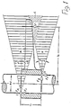
- the invention takes advantage of the knowledge of friction on a cylindrical guide, as shown in Fig.1.
- the force F is shown with its line of action.
- the bushing turns clockwise and attaches itself to the cylinder at the top left at point I and at the bottom right at point II.
- the associated normal forces F A andF B are directed against the socket.
- the force F tries to move the bushing downwards and the friction forces Fr are thus directed upwards.
- the lines of action of the normal and the frictional forces lie within the friction cone R because the frictional force never exceeds the value R ⁇ F ⁇ tan ⁇ of the two friction cones R can lie.
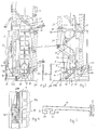
- FIG. 2 and 3 show the arrangement in the right-hand rail arrangement, with the illustration in FIG. 2 seen from the rear and with the illustration in FIG. 3 seen from the slat side.
- Parallel T-rails 21 are integrally connected to the wall 20 of a guide box 19 for accommodating the support members 15 and lamellar carriers.
- a guide carriage 2 slides on these rails 21.
- a tension band 1 slides freely through this guide carriage 2 and is fastened between a band fastening 39 and a release guide 40 by means of a screw connection 39a.
- the trigger guide 40 is in one piece with a shoe 30, which is rigidly connected in the event of a malfunction by which the curtain is stuck.
- the guide carriage 2 carries a support 22 on the curtain side, which is operatively connected to the lumella carrier 15.
- An elongated tab 4 is articulated centrally on the disk carrier 15 by means of a pivot pin 14.
- This tab 4 is provided in its lower part with a slot 7 into which a pin 6 engages, which can be moved up and down in the slot 7 to a limited extent.
- the pin 6 is located at the end of a locking lever 8, which locking lever 8 is equipped with two opposing brake flaps 32, 33 (FIG: 5). These brake flaps 32, 33 encompass the yoke of the T-shaped rail 21, each with a rear engagement tab 34, 35 (FIG. 5).
- the locking lever 8 is located between two cams 12a and 12b located vertically one above the other as a rotary bearing. Under the pin 6 there is a support 10 for the locking lever 8 on the guide carriage 2.
- This support 10 has the task of holding the locking lever 8 in a horizontal position when lowering and lifting the curtain so that it does not rotate under the weight of the curtain can and would thus exert frictional forces on the rail.
- the securing bar 31 At its end opposite the brake shoes, has a guide slot 36 for the tension band 1.
- the safety bar 31 rests on the side of the brake shoes 32, 33 on a support surface of the strap fastener 40, so that when the curtain is lifted up, the safety bar rests on one end on this support surface and on the other hand on a support 38 integrally formed on the guide carriage 2.
- the safety bar 31 is thus in a horizontal position during normal lifting of the curtain by means of the elevator belt 1 and the brake shoes 32, 33 cannot exert any frictional forces on the rail.
- the guide carriage 2 stops and supports the securing beam 31 on one side with the support, while the shoe 30 pulls the strap fastener 40 with the contact surface downward, so that the securing bar is inclined and the brake shoes 32, 33 generate a frictional force on the guide rail.
- the drawstring 1 can thus move downward with the weight of the shoe 30 without the curtain moving. Only when the drawstring 1 is pulled up again, and the strap fastener 40 with the support surface has brought the securing bar 31 back into the horizontal position and thus the brake shoes 32, 33 no longer lie against the guide rail 21, can the curtain move up again will. In this way, it can be reliably prevented that the blinds cannot be damaged if they are handled incorrectly.
- the brake flaps of the locking lever 8 act in exactly the same way as the securing bar. These brake flaps each enclose the yoke of the rail a back tab.
- the locking lever 8 lies between two vertically superimposed cams 12a and 12b as a rotary bearing.
- This support 10 has the task of holding the locking lever in a horizontal position when lowering and lifting the curtain so that it cannot rotate under the weight of the curtain and thus exerts frictional forces on the rail, so that a similar case could occur as described above.
- the carriage 2 With the elevator belt 1, the carriage 2 is pulled up and by resting on the support 22 the profiles are horizontal and can be gathered. When lowering, the elevator belt 1 brakes the otherwise free fall of the carriage 2 so that it slides downwards in synchronization with the curtain due to its own weight.
- the plate pack 3, of which only the bottom plate is shown, is supported by the tab 4 on the slide 2 in a shell 5 by means of a pin 11.
- the support 10 is also located on this pin.
- the tab 4 is pivotally connected to the lowermost lamella of the disk pack 3 via the hinge pin 14. If the completely lowered curtain on its lowermost slat 3 of the slat package is now pushed up, the pin 6 on the locking lever 8 in the slot 7 is pulled upward. The positive engagement of the brake flaps 9 on the yoke 17b of the rail 21 causes the brake flaps 9 to exert frictional forces Fr on the web 17b of the rail 21, as described above in FIG become large, and it is therefore not possible for the locking lever 8. the tab 4 and thus the lowest slat of the curtain moved can be. This guarantees an absolutely flawless securing of the curtain.
- the locking lever 8 comes to rest in the horizontal position due to the support 10 and the cams 12a, 12b and the brake flaps 9 slide up smoothly on the rail.
- the locking only takes effect when the lowermost profile bar 3 is raised, without any further action by the operator being necessary. If the brake flaps 9 also came into effect, nobody notices this, because when the brake flaps 9 are pulled up, they detach themselves from the rail 21 and the curtain can be operated without any additional effort.
Landscapes
- Engineering & Computer Science (AREA)
- Structural Engineering (AREA)
- Architecture (AREA)
- Civil Engineering (AREA)
- Operating, Guiding And Securing Of Roll- Type Closing Members (AREA)
- Blinds (AREA)
- Filtering Of Dispersed Particles In Gases (AREA)
Applications Claiming Priority (4)
| Application Number | Priority Date | Filing Date | Title |
|---|---|---|---|
| CH136093A CH687635A5 (de) | 1993-05-04 | 1993-05-04 | Hubsicherung an Raffjalousien. |
| CH1360/93 | 1993-05-04 | ||
| CH189793A CH688005A5 (de) | 1993-06-24 | 1993-06-24 | Fallsicherung bei einer Raff- oder Rolljalousie. |
| CH1897/93 | 1993-06-24 |
Publications (3)
| Publication Number | Publication Date |
|---|---|
| EP0623732A2 true EP0623732A2 (fr) | 1994-11-09 |
| EP0623732A3 EP0623732A3 (fr) | 1995-07-05 |
| EP0623732B1 EP0623732B1 (fr) | 1999-01-13 |
Family
ID=25687446
Family Applications (1)
| Application Number | Title | Priority Date | Filing Date |
|---|---|---|---|
| EP94106877A Expired - Lifetime EP0623732B1 (fr) | 1993-05-04 | 1994-05-03 | Dispositif de sécurité pour stores vénitiens ou stores à rouleau |
Country Status (3)
| Country | Link |
|---|---|
| EP (1) | EP0623732B1 (fr) |
| AT (1) | ATE175752T1 (fr) |
| DE (1) | DE59407616D1 (fr) |
Family Cites Families (5)
| Publication number | Priority date | Publication date | Assignee | Title |
|---|---|---|---|---|
| DE3037733A1 (de) * | 1980-10-06 | 1982-07-22 | Emil Schenker AG, 5012 Schönenwerd | Rafflamellenstore |
| DE3037701A1 (de) * | 1980-10-06 | 1982-07-15 | Emil Schenker AG, 5012 Schönenwerd | Rafflamellenstore, rolladen o.dgl. |
| EP0127749B1 (fr) * | 1983-05-18 | 1989-01-25 | Baumann AG Rolladenfabrik | Dispositif de sécurité contre le levage et store à lamelles comportant un tel dispositif |
| CH673872A5 (fr) * | 1986-12-19 | 1990-04-12 | Griesser Ag | |
| DE3809058A1 (de) * | 1988-02-25 | 1989-09-07 | Jan Hofman | Rolladen fuer oeffnungsabschluesse |
-
1994
- 1994-05-03 AT AT94106877T patent/ATE175752T1/de not_active IP Right Cessation
- 1994-05-03 EP EP94106877A patent/EP0623732B1/fr not_active Expired - Lifetime
- 1994-05-03 DE DE59407616T patent/DE59407616D1/de not_active Expired - Fee Related
Also Published As
| Publication number | Publication date |
|---|---|
| DE59407616D1 (de) | 1999-02-25 |
| EP0623732B1 (fr) | 1999-01-13 |
| EP0623732A3 (fr) | 1995-07-05 |
| ATE175752T1 (de) | 1999-01-15 |
Similar Documents
| Publication | Publication Date | Title |
|---|---|---|
| DE69802919T2 (de) | Führungsvorrichtung für flexibles hubtor | |
| CH660507A5 (de) | Vorrichtung zum betaetigen einer schiebetuer. | |
| CH653090A5 (de) | Rafflamellenstore. | |
| WO1999015754A1 (fr) | Porte roulante avec vantail flexible | |
| EP3231979B1 (fr) | Ascenseur, en particulier monte-charges, pour le transport en hauteur de charges et agencement comprenant une échelle et un tel ascenseur | |
| DE3744590C1 (de) | Schraegmarkise mit anschliessendem vertikalem Bereich | |
| DE3511246A1 (de) | Abschirm- oder schutzvorrichtung fuer wandoeffnungen o.dgl., insbesondere ein rolladen oder eine jalousie | |
| CH671264A5 (fr) | ||
| EP0623732B1 (fr) | Dispositif de sécurité pour stores vénitiens ou stores à rouleau | |
| DE19928574C2 (de) | Arbeitsbühne | |
| CH682339A5 (fr) | ||
| EP0675261B1 (fr) | Porte enroulable avec un vantail de porte souple | |
| EP0887509A1 (fr) | Store vénitien avec lamelles horizontales | |
| DE3038315C2 (fr) | ||
| CH687635A5 (de) | Hubsicherung an Raffjalousien. | |
| DE4315427A1 (de) | Schrank | |
| DE2814345A1 (de) | Tor, vorzugsweise fuer industriegebaeude | |
| EP0621391B1 (fr) | Store vénitien | |
| CH688005A5 (de) | Fallsicherung bei einer Raff- oder Rolljalousie. | |
| EP3741953A1 (fr) | Système de fermeture roulante pour former un agencement de fermeture roulante sur un angle et agencement de fermeture roulante en coin | |
| DE4114446C2 (de) | Vorrichtung zum Einbau eines Türblatts in eine Türöffnung | |
| DE202005015152U1 (de) | Vorrichtung zum Transportieren von Türen | |
| DE3139202A1 (de) | "gardinenleiste" | |
| DE1759993B2 (de) | Selbsttaetige sicherung eines rolladens od.dgl. gegen unbefugtes hochschieben von aussen | |
| DE3702545C2 (fr) |
Legal Events
| Date | Code | Title | Description |
|---|---|---|---|
| PUAI | Public reference made under article 153(3) epc to a published international application that has entered the european phase |
Free format text: ORIGINAL CODE: 0009012 |
|
| AK | Designated contracting states |
Kind code of ref document: A2 Designated state(s): AT BE CH DE DK ES FR GB GR IT LI LU NL SE |
|
| PUAL | Search report despatched |
Free format text: ORIGINAL CODE: 0009013 |
|
| AK | Designated contracting states |
Kind code of ref document: A3 Designated state(s): AT BE CH DE DK ES FR GB GR IT LI LU NL SE |
|
| 17P | Request for examination filed |
Effective date: 19950817 |
|
| 17Q | First examination report despatched |
Effective date: 19961227 |
|
| GRAG | Despatch of communication of intention to grant |
Free format text: ORIGINAL CODE: EPIDOS AGRA |
|
| GRAG | Despatch of communication of intention to grant |
Free format text: ORIGINAL CODE: EPIDOS AGRA |
|
| GRAG | Despatch of communication of intention to grant |
Free format text: ORIGINAL CODE: EPIDOS AGRA |
|
| GRAH | Despatch of communication of intention to grant a patent |
Free format text: ORIGINAL CODE: EPIDOS IGRA |
|
| GRAH | Despatch of communication of intention to grant a patent |
Free format text: ORIGINAL CODE: EPIDOS IGRA |
|
| GRAA | (expected) grant |
Free format text: ORIGINAL CODE: 0009210 |
|
| AK | Designated contracting states |
Kind code of ref document: B1 Designated state(s): AT BE CH DE DK ES FR GB GR IT LI LU NL SE |
|
| PG25 | Lapsed in a contracting state [announced via postgrant information from national office to epo] |
Ref country code: SE Free format text: THE PATENT HAS BEEN ANNULLED BY A DECISION OF A NATIONAL AUTHORITY Effective date: 19990113 Ref country code: NL Free format text: LAPSE BECAUSE OF FAILURE TO SUBMIT A TRANSLATION OF THE DESCRIPTION OR TO PAY THE FEE WITHIN THE PRESCRIBED TIME-LIMIT Effective date: 19990113 Ref country code: GR Free format text: LAPSE BECAUSE OF NON-PAYMENT OF DUE FEES Effective date: 19990113 Ref country code: GB Free format text: LAPSE BECAUSE OF NON-PAYMENT OF DUE FEES Effective date: 19990113 Ref country code: ES Free format text: THE PATENT HAS BEEN ANNULLED BY A DECISION OF A NATIONAL AUTHORITY Effective date: 19990113 |
|
| REF | Corresponds to: |
Ref document number: 175752 Country of ref document: AT Date of ref document: 19990115 Kind code of ref document: T |
|
| REG | Reference to a national code |
Ref country code: CH Ref legal event code: EP |
|
| REG | Reference to a national code |
Ref country code: CH Ref legal event code: NV Representative=s name: NOVATOR AG |
|
| REF | Corresponds to: |
Ref document number: 59407616 Country of ref document: DE Date of ref document: 19990225 |
|
| ET | Fr: translation filed | ||
| ITF | It: translation for a ep patent filed | ||
| PG25 | Lapsed in a contracting state [announced via postgrant information from national office to epo] |
Ref country code: DK Free format text: LAPSE BECAUSE OF FAILURE TO SUBMIT A TRANSLATION OF THE DESCRIPTION OR TO PAY THE FEE WITHIN THE PRESCRIBED TIME-LIMIT Effective date: 19990413 |
|
| PG25 | Lapsed in a contracting state [announced via postgrant information from national office to epo] |
Ref country code: LU Free format text: LAPSE BECAUSE OF NON-PAYMENT OF DUE FEES Effective date: 19990503 |
|
| NLV1 | Nl: lapsed or annulled due to failure to fulfill the requirements of art. 29p and 29m of the patents act | ||
| GBV | Gb: ep patent (uk) treated as always having been void in accordance with gb section 77(7)/1977 [no translation filed] |
Effective date: 19990113 |
|
| PLBE | No opposition filed within time limit |
Free format text: ORIGINAL CODE: 0009261 |
|
| STAA | Information on the status of an ep patent application or granted ep patent |
Free format text: STATUS: NO OPPOSITION FILED WITHIN TIME LIMIT |
|
| 26N | No opposition filed | ||
| PGFP | Annual fee paid to national office [announced via postgrant information from national office to epo] |
Ref country code: CH Payment date: 20000515 Year of fee payment: 7 |
|
| PGFP | Annual fee paid to national office [announced via postgrant information from national office to epo] |
Ref country code: FR Payment date: 20000530 Year of fee payment: 7 Ref country code: AT Payment date: 20000530 Year of fee payment: 7 |
|
| PGFP | Annual fee paid to national office [announced via postgrant information from national office to epo] |
Ref country code: BE Payment date: 20000531 Year of fee payment: 7 |
|
| PGFP | Annual fee paid to national office [announced via postgrant information from national office to epo] |
Ref country code: DE Payment date: 20000722 Year of fee payment: 7 |
|
| PG25 | Lapsed in a contracting state [announced via postgrant information from national office to epo] |
Ref country code: AT Free format text: LAPSE BECAUSE OF NON-PAYMENT OF DUE FEES Effective date: 20010503 |
|
| PG25 | Lapsed in a contracting state [announced via postgrant information from national office to epo] |
Ref country code: BE Free format text: LAPSE BECAUSE OF NON-PAYMENT OF DUE FEES Effective date: 20010531 |
|
| PG25 | Lapsed in a contracting state [announced via postgrant information from national office to epo] |
Ref country code: LI Free format text: LAPSE BECAUSE OF NON-PAYMENT OF DUE FEES Effective date: 20010602 Ref country code: CH Free format text: LAPSE BECAUSE OF NON-PAYMENT OF DUE FEES Effective date: 20010602 |
|
| BERE | Be: lapsed |
Owner name: E. KINDT AG VORMALS HANS KIEFER A.G. Effective date: 20010531 |
|
| REG | Reference to a national code |
Ref country code: CH Ref legal event code: PL |
|
| PG25 | Lapsed in a contracting state [announced via postgrant information from national office to epo] |
Ref country code: FR Free format text: LAPSE BECAUSE OF NON-PAYMENT OF DUE FEES Effective date: 20020131 |
|
| PG25 | Lapsed in a contracting state [announced via postgrant information from national office to epo] |
Ref country code: DE Free format text: LAPSE BECAUSE OF NON-PAYMENT OF DUE FEES Effective date: 20020301 |
|
| PG25 | Lapsed in a contracting state [announced via postgrant information from national office to epo] |
Ref country code: IT Free format text: LAPSE BECAUSE OF NON-PAYMENT OF DUE FEES;WARNING: LAPSES OF ITALIAN PATENTS WITH EFFECTIVE DATE BEFORE 2007 MAY HAVE OCCURRED AT ANY TIME BEFORE 2007. THE CORRECT EFFECTIVE DATE MAY BE DIFFERENT FROM THE ONE RECORDED. Effective date: 20050503 |