EP0625103B1 - Kommunikationssystem - Google Patents
Kommunikationssystem Download PDFInfo
- Publication number
- EP0625103B1 EP0625103B1 EP93917406A EP93917406A EP0625103B1 EP 0625103 B1 EP0625103 B1 EP 0625103B1 EP 93917406 A EP93917406 A EP 93917406A EP 93917406 A EP93917406 A EP 93917406A EP 0625103 B1 EP0625103 B1 EP 0625103B1
- Authority
- EP
- European Patent Office
- Prior art keywords
- fault
- end station
- stations
- medium
- station
- Prior art date
- Legal status (The legal status is an assumption and is not a legal conclusion. Google has not performed a legal analysis and makes no representation as to the accuracy of the status listed.)
- Expired - Lifetime
Links
Images

Classifications
-
- H—ELECTRICITY
- H04—ELECTRIC COMMUNICATION TECHNIQUE
- H04L—TRANSMISSION OF DIGITAL INFORMATION, e.g. TELEGRAPHIC COMMUNICATION
- H04L43/00—Arrangements for monitoring or testing data switching networks
- H04L43/50—Testing arrangements
-
- G—PHYSICS
- G06—COMPUTING OR CALCULATING; COUNTING
- G06F—ELECTRIC DIGITAL DATA PROCESSING
- G06F11/00—Error detection; Error correction; Monitoring
- G06F11/22—Detection or location of defective computer hardware by testing during standby operation or during idle time, e.g. start-up testing
-
- H—ELECTRICITY
- H04—ELECTRIC COMMUNICATION TECHNIQUE
- H04L—TRANSMISSION OF DIGITAL INFORMATION, e.g. TELEGRAPHIC COMMUNICATION
- H04L12/00—Data switching networks
- H04L12/28—Data switching networks characterised by path configuration, e.g. LAN [Local Area Networks] or WAN [Wide Area Networks]
- H04L12/42—Loop networks
-
- H—ELECTRICITY
- H04—ELECTRIC COMMUNICATION TECHNIQUE
- H04L—TRANSMISSION OF DIGITAL INFORMATION, e.g. TELEGRAPHIC COMMUNICATION
- H04L12/00—Data switching networks
- H04L12/28—Data switching networks characterised by path configuration, e.g. LAN [Local Area Networks] or WAN [Wide Area Networks]
- H04L12/42—Loop networks
- H04L12/427—Loop networks with decentralised control
- H04L12/433—Loop networks with decentralised control with asynchronous transmission, e.g. token ring, register insertion
-
- H—ELECTRICITY
- H04—ELECTRIC COMMUNICATION TECHNIQUE
- H04L—TRANSMISSION OF DIGITAL INFORMATION, e.g. TELEGRAPHIC COMMUNICATION
- H04L12/00—Data switching networks
- H04L12/28—Data switching networks characterised by path configuration, e.g. LAN [Local Area Networks] or WAN [Wide Area Networks]
- H04L12/42—Loop networks
- H04L12/437—Ring fault isolation or reconfiguration
Definitions
- the invention relates to a communication system, for example a ring communication system or an open ended system, having a number of end station ports which enable respective end stations (such as computers and word processing terminals) to transmit onto and receive signals from a signal carrying medium.
- a communication system for example a ring communication system or an open ended system, having a number of end station ports which enable respective end stations (such as computers and word processing terminals) to transmit onto and receive signals from a signal carrying medium.
- Communication systems of this type are highly sophisticated and rely on complex protocols to enable communication to be achieved between end stations connected to the signal carrying medium. Examples of such protocols are the token ring protocol and the FDDI system. These protocols incorporate certain fault recovery procedures if a fault should arise within the system. However, with increasing numbers of end stations being connected to communication systems, the existing fault recovery techniques tend to be slow and in addition the existing fault recovery procedures provide incomplete protection against the erroneous operation of the end stations themselves, against any out of specification operation of the system or major cable faults.
- ports are connected via so-called hub units which themselves can incorporate certain intelligence to enable faults to be detected.
- hub units which themselves can incorporate certain intelligence to enable faults to be detected.
- additional end stations within the hub are incorporated on the system which are used simply to detect if the network or system is operational or faulty.
- Internal control circuits can then process the information returned by the end stations and force other end stations connected to the hub to be removed in turn until the network or system is again operational.
- fault recovery techniques can be slow particularly in practical implementations where 80 or more end stations may be connected to a single hub. Multiple faults will further increase fault recovery time.
- EP-A-0244775 discloses a ring network system in which terminal stations are connected through branch lines to a number of line concentrators.
- Each line concentrator includes control switches capable of disconnecting branch lines from the ring network whilst allowing the network to continue functioning.
- the disconnected branch line forms a local ring through cooperation with an internal transmission line.
- the line concentrator can then undergo internal diagnosis without disturbing communication among other line concentrators.
- EP-A-0431635 discloses a ring type LAN with a fault processing system.
- Each station is provided with a timer for measuring the transmission time of a beacon or fault notifying frame. Should the timer run out of time, the station forms a loop back with the adjoining station temporarily removing both stations from the ring. The stations then undergo internal fault analysis and rejoin the network if they are normal thus leaving the faulty station removed from the ring.
- a method of analysing a communication system to locate the source of a fault comprising a signal carrying medium coupled to a series of end station ports which enable respective end stations to transmit signals onto and receive signals from the medium; and control means for controlling the connection of end stations to the medium via the ports, comprises, upon detection of the fault by fault analysis means (10), disconnecting end stations in series from the medium and detecting whether or not a fault condition still exists, characterized in that said fault analysis means, in response to the detection of a fault, causes the control means firstly to disconnect an end station which has previously been characterised as the most likely to be the source of the fault.
- this aspect of the invention enables at least the first station which is disconnected to be one which is more likely to have caused the fault.
- the first end station to be disconnected could be the most recent end station to have been connected to the system or the last end station which has been diagnosed as causing a fault.
- the next end station to be disconnected could be the one which is characterised as the next likely to be the source of the fault. For example, if the first station to be disconnected is the last to have joined then the next to be disconnected could be the last to have been diagnosed as causing a previous fault. Alternatively, the second and succeeding stations to be disconnected could be those which have joined the system in increasing times.
- This method provides a rapid and systematic way of locating a faulty end station.
- the group of stations which are disconnected at each stage will be substantially half of the remaining end stations.
- a communication system comprises a signal carrying medium coupled to a series of end station ports which enable respective end stations to transmit signals onto and receive signals from the medium; and control means for controlling the connection of end stations to the medium via the ports characterized in that the system further comprises a memory for storing the address of the station characterized as most likely to develop a fault, and fault analysis means for detecting the source of the fault on the system, the fault analysis means including means which, upon detection of the fault, disconnects end stations in series from the medium and detects whether or not the fault condition still exists and wherein the fault analysis means is adapted to respond to the detection of a fault to cause the control means to disconnect the end station which has previously been characterised as the most likely to be the source of the fault and whose address is stored in the memory.
- control means and fault analysis means are provided within a concentrator unit and will be defined at least in part by a suitably programmed microprocessor.
- the protocol provides a so-called error recovery facility in which when a fault is detected, an error recovery frame is transmitted around the ring indicating the address of one or more end stations adjacent to the fault.
- error recovery facility in which when a fault is detected, an error recovery frame is transmitted around the ring indicating the address of one or more end stations adjacent to the fault.
- this information has simply been displayed on a monitor and the operator has had to deduce from that information the source of the fault.
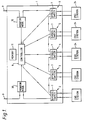
- FIG 1 illustrates a concentrator 1 having a number of ports 2-6 each of which comprises a ring bypass switch 7 controlled by a control circuit 8 incorporating a microprocessor.
- Each bypass switch 7 can be controlled either to pass received signals directly from an input port to an output port or to an end station 24 coupled to the switch.
- the concentrator 1 is connected to the remainder of the network via a uni-directional communication medium 9 such as copper wire or optical fibre.
- a uni-directional communication medium 9 such as copper wire or optical fibre.
- the concentrator 1 also includes a pair of monitor end stations or nodes 10,30 one of whose purposes is to detect the presence of faults on the ring.
- the controller 8 records in a memory 11 the addresses of either or both of the most recent end station to be connected to the ring and the last end station to have been the source of a fault.
- the controller 8 commences its analysis to locate the source of the fault by firstly actuating the bypass switch 7 associated with one of the end stations whose address is stored in the memory 11. The likelihood is that it is the last end station to have joined the ring or the last to have been the source of a fault which is the source of the current fault.
- the controller 8 will a) revert to conventional procedures to locate the actual source of the fault, b) make use of the procedures to be described below in connection with Figure 2, or c) next check the penultimate end station to have joined the system if this is recorded in the memory 11.
- Process c) could be extended to successively older end stations or end stations which have been the source of successively older faults.
- An alternative approach to locating the source of the fault involves a so-called binary chop process.
- the controller 8 when one of the monitor nodes 10, 30 detects a fault, the controller 8 initially bypasses half the end stations connected to the concentrator 1. If therefore there are N such stations then the controller 8 will firstly bypass stations 1 to N/2 inclusive (step 20). The controller 8 will then determine whether the downstream monitor node 10 continues to detect a fault (step 21). If a fault is still detected, this indicates that one of the non-bypassed stations is the source of the fault. Consequently the controller 8 will then bypass half of the remaining non-bypassed stations, for example, stations (N/2)+1 to 3N/4 inclusive (step 22). The controller 8 again determines whether the downstream monitor node 10 has detected the fault and the process continues until only one station is present, namely the faulty station.
- step 21 If in step 21 no fault is detected, this indicates that it is one of the bypassed stations which has caused the fault. Ccnsequently, half of those bypassed stations are reinserted on the ring while the remaining stations, for example 1 to N/4 inclusive remain bypassed (step 23). The presence or absence of a fault is then detected and the process repeated until an end station is isolated as the source of the fault.
Landscapes
- Engineering & Computer Science (AREA)
- Computer Networks & Wireless Communication (AREA)
- Signal Processing (AREA)
- Theoretical Computer Science (AREA)
- General Engineering & Computer Science (AREA)
- Physics & Mathematics (AREA)
- Quality & Reliability (AREA)
- General Physics & Mathematics (AREA)
- Computer Hardware Design (AREA)
- Small-Scale Networks (AREA)
- Data Exchanges In Wide-Area Networks (AREA)
- Maintenance And Management Of Digital Transmission (AREA)
- Monitoring And Testing Of Transmission In General (AREA)
Claims (9)
- Verfahren zur Analyse eines Kommunikationssystems, um eine Fehlerquelle zu lokalisieren, wobei das System ein signaltragendes Medium (9) enthält, das mit einer Anzahl von Ports (2-6) für Datenendstationen verbunden ist, die es den jeweiligen Datenendstationen (24) ermöglichen, Signale an das Medium abzugeben und von dem Medium zu empfangen; sowie eine Kontrolleinrichtung (8) um die Verbindung der Datenendstationen über die Ports zu dem Medium zu kontrollieren, und wobei das Verfahren einschließt, daß nach der Feststellung eines Fehlers durch eine Fehleranalyseeinrichtung (10) der Reihe nach die Datenendstationen (24) von dem Medium (9) ausgekoppelt werden und dabei festgestellt wird, ob weiterhin noch ein Fehlerzustand besteht oder nicht, dadurch gekennzeichnet, daß die Fehleranalyseeinrichtung (10) nach der Feststellung eines Fehlers bewirkt, daß die Kontrolleinrichtung (8) zuerst eine Datenendstation (24) auskoppelt, die zuvor als die wahrscheinlichste Fehlerquelle gekennzeichnet wurde.
- Verfahren nach Anspruch 1, bei dem die Datenendstation (24), die als erste ausgekoppelt wird, eine der Datenendstationen ist, die zuletzt mit dem System verbunden und als Fehlerquelle identifiziert wurde.
- Verfahren nach Anspruch 1 oder 2, bei dem, wenn die erste ausgekoppelte Datenendstation nicht als Fehlerquelle identifiziert wird, die als nächste ausgekoppelte Datenendstationen (24), die als nächstwahrscheinliche Fehlererquelle gekennzeichnete Datenendstation ist, und bei dem dieser Vorgang wiederholbar ist, so daß die als nächste ausgekoppelte Datenendstation wiederum als die nächstwahrscheinliche Fehlerquelle gekennzeichnet ist.
- Verfahren nach Anspruch 3, bei dem die Datenendstationen ausgekoppelt werden bis die Datenendstation, die den Fehler verursacht, lokalisiert ist.
- Verfahren nach Anspruch 1 oder 2, bei dem, wenn die erste ausgekoppelte Datenendstation nicht als Fehlerquelle identifiziert wird, das Verfahren dann weiterhina) bewirkt, daß die Kontrolleinrichtung (8) eine Gruppe von zwei oder mehr der verbleibenden Datenendstationen auskoppelt,b) feststellt, ob ein Fehler vorhanden ist,c)i) wenn ein Fehler vorhanden ist, eine Gruppe der verbleibenden Endstationen (24) auskoppelt, oderii) wenn kein Fehler vorhanden ist, eine Gruppe der zuvor ausgekoppelten Datenendstationen wieder einkoppelt,d) feststellt, ob ein Fehler vorhanden ist, unde) die Schritte (c) und (d) wiederholt bis die Datenendstation (24), die den Fehler verursacht, lokalisiert ist.
- Verfahren nach Anspruch 5, bei dem die Gruppe der Datenendstationen, die bei jedem Schritt ausgekoppelt werden im wesentlichen die Hälfte der verbleibenden Datenendstationen umfaßt.
- Kommunikationssystem, wobei das System ein signaltragendes Medium enthält, das mit einer Anzahl von Ports (2-6) für Datenendstationen verbunden ist, die es den jeweiligen Datenendstationen (24) ermöglichen, Signale an das Medium (9) abzugeben und von dem Medium zu empfangen, sowie eine Kontrolleinrichtung (8) um die Verbindung der Datenendstationen (24) über die Ports (2-6) zu dem Medium (9) zu kontrollieren, dadurch gekennzeichnet, daß das System weiterhin einen Speicher (11) zur Speicherung der Adresse der Datenendstation enthält, die als wahrscheinlichste Fehlerquelle gekennzeichnet ist, sowie eine Fehleranalyseeinrichtung (10), um die Fehlerquelle im System festzustellen, wobei die Fehleranalyseeinrichtung Einrichtungen einschließt, die nach der Feststellung eines Fehlers die Datenendstationen (24) der Reihe nach vom dem Medium (9) auskoppelt und feststellt, ob der Fehlerzustand noch weiterhin besteht, und wobei die Fehleranalyseeinrichtung derart ausgebildet ist, daß nach der Feststellung eines Fehlers die Kontrolleinrichtung (8) die Datenendstation (24) auskoppelt, die zuvor als die wahrscheinlichste Fehlerquelle gekennzeichnet wurde und deren Adresse noch in dem Speicher (11) gespeichert ist.
- System nach Anspruch 7, bei dem die Kontrolleinrichtung (8) und die Fehleranalyseeinrichtung (10) in einer Konzentratoreinheit (1) vorgesehen sind und wenigstens teilweise durch einen entsprechend programmierten Mikroprozessor definiert sind.
- System nach Anspruch 7 oder 8, wobei das System ein Ringkommunikationssystem ist.
Priority Applications (2)
| Application Number | Priority Date | Filing Date | Title |
|---|---|---|---|
| EP96201129A EP0727896A3 (de) | 1992-02-07 | 1993-01-29 | Kommunikationssystem |
| EP96201128A EP0727895A3 (de) | 1992-02-07 | 1993-01-29 | Kommunikationssystem |
Applications Claiming Priority (3)
| Application Number | Priority Date | Filing Date | Title |
|---|---|---|---|
| GB929202666A GB9202666D0 (en) | 1992-02-07 | 1992-02-07 | Communication system |
| GB9202666 | 1992-02-07 | ||
| PCT/GB1993/000198 WO1993016540A2 (en) | 1992-02-07 | 1993-01-29 | Communication system |
Related Child Applications (2)
| Application Number | Title | Priority Date | Filing Date |
|---|---|---|---|
| EP96201129.2 Division-Into | 1996-05-07 | ||
| EP96201128.4 Division-Into | 1996-05-07 |
Publications (2)
| Publication Number | Publication Date |
|---|---|
| EP0625103A1 EP0625103A1 (de) | 1994-11-23 |
| EP0625103B1 true EP0625103B1 (de) | 1997-07-16 |
Family
ID=10710030
Family Applications (3)
| Application Number | Title | Priority Date | Filing Date |
|---|---|---|---|
| EP96201128A Withdrawn EP0727895A3 (de) | 1992-02-07 | 1993-01-29 | Kommunikationssystem |
| EP96201129A Withdrawn EP0727896A3 (de) | 1992-02-07 | 1993-01-29 | Kommunikationssystem |
| EP93917406A Expired - Lifetime EP0625103B1 (de) | 1992-02-07 | 1993-01-29 | Kommunikationssystem |
Family Applications Before (2)
| Application Number | Title | Priority Date | Filing Date |
|---|---|---|---|
| EP96201128A Withdrawn EP0727895A3 (de) | 1992-02-07 | 1993-01-29 | Kommunikationssystem |
| EP96201129A Withdrawn EP0727896A3 (de) | 1992-02-07 | 1993-01-29 | Kommunikationssystem |
Country Status (6)
| Country | Link |
|---|---|
| US (1) | US5710777A (de) |
| EP (3) | EP0727895A3 (de) |
| JP (2) | JP3183668B2 (de) |
| DE (1) | DE69312267T2 (de) |
| GB (1) | GB9202666D0 (de) |
| WO (1) | WO1993016540A2 (de) |
Families Citing this family (39)
| Publication number | Priority date | Publication date | Assignee | Title |
|---|---|---|---|---|
| SE514658C2 (sv) * | 1994-12-21 | 2001-03-26 | Ericsson Telefon Ab L M | Nodarkitektur för tillämpning av optisk optimering (OADM) |
| US6441931B1 (en) | 1996-02-23 | 2002-08-27 | Nortel Networks Limited | Method and apparatus for monitoring a dedicated communications medium in a switched data network |
| US6047321A (en) * | 1996-02-23 | 2000-04-04 | Nortel Networks Corporation | Method and apparatus for monitoring a dedicated communications medium in a switched data network |
| DE19745021B4 (de) * | 1996-10-29 | 2008-08-28 | Keymile Ag | Netzwerk für paketorientierten Datenverkehr |
| US6138199A (en) * | 1997-01-23 | 2000-10-24 | Sun Microsystems, Inc. | System for data transfer in a ring topology comprising selectors to selectively bypass external devices or a downstream device based upon presence indications |
| US6411598B1 (en) | 1997-03-12 | 2002-06-25 | Mci Communications Corporation | Signal conversion for fault isolation |
| EP0972410B1 (de) | 1997-03-12 | 2006-10-04 | Alcatel Network Systems, Inc. | Verfahren und system zur verteilter wiederherstellung eines fernmeldenetzes |
| US6496476B1 (en) * | 1997-03-12 | 2002-12-17 | Worldcom, Inc. | System and method for restricted reuse of intact portions of failed paths |
| JPH10262000A (ja) * | 1997-03-19 | 1998-09-29 | Fujitsu Ltd | パッシブオプチカルネットワークにおける障害復旧方法及び装置 |
| JPH11168488A (ja) * | 1997-12-05 | 1999-06-22 | Sumitomo Wiring Syst Ltd | ハブ切換装置、これを用いた配線システム及びハブ切換装置の使用方法 |
| US6295146B1 (en) * | 1998-01-14 | 2001-09-25 | Mci Communications Corporation | System and method for sharing a spare channel among two or more optical ring networks |
| US6167026A (en) * | 1998-05-01 | 2000-12-26 | Emulex Corporation | Programmable error control circuit |
| US6882620B1 (en) * | 1998-05-27 | 2005-04-19 | Emc Corporation | Token exchange system with fault protection |
| US6404733B1 (en) | 1998-09-08 | 2002-06-11 | Mci Worldcom, Inc. | Method of exercising a distributed restoration process in an operational telecommunications network |
| US6418117B1 (en) | 1998-09-08 | 2002-07-09 | Mci Worldcom, Inc. | Out of band messaging in a DRA network |
| US6337846B1 (en) | 1998-09-08 | 2002-01-08 | Mci Worldcom, Inc. | Quantification of the quality of spare links in a telecommunications network |
| US6294991B1 (en) | 1998-09-08 | 2001-09-25 | Mci Communications Corporation | Method and system therefor for ensuring a true activation of distributed restoration in a telecommunications network |
| US6888800B1 (en) * | 1998-11-14 | 2005-05-03 | Emulex Design & Manufacturing Corporation | High performance digital loop diagnostic technology |
| US6898184B1 (en) * | 1998-11-15 | 2005-05-24 | Hewlett-Packard Development Company, L.P. | Private arbitrated loop self-test management for a fibre channel storage enclosure |
| US7382736B2 (en) | 1999-01-12 | 2008-06-03 | Mcdata Corporation | Method for scoring queued frames for selective transmission through a switch |
| US6813240B1 (en) | 1999-06-11 | 2004-11-02 | Mci, Inc. | Method of identifying low quality links in a telecommunications network |
| AU2611701A (en) * | 1999-12-30 | 2001-07-16 | Computer Associates Think, Inc. | System and method for topology based monitoring of networking devices |
| US6574753B1 (en) * | 2000-01-10 | 2003-06-03 | Emc Corporation | Peer link fault isolation |
| FR2814559B1 (fr) * | 2000-09-27 | 2003-01-24 | Sagem | Procede de codage d'une matrice de connexion d'une artere de transmission de donnees et processeur et produit de logiciel pour la mise en oeuvre du procede |
| DE10047923C2 (de) * | 2000-09-27 | 2003-04-10 | Siemens Ag | Verfahren zur Erzeugung einer Verbindungs-Redundanz für ein serielles Kommunikationssystem mit einer Mastereinheit und einer Mehrzahl von Slaveeinheiten, die untereinander als Aneinanderreihung von Punkt-zu-Punkt-Verbindungen in Linientopologie verbunden sind, sowie korrespondierendes serielles Kommunikationssystem |
| US6889345B2 (en) * | 2001-10-19 | 2005-05-03 | Hewlett-Packard Development Company, Lp. | System and method for locating a failed storage device in a data storage system |
| US6766482B1 (en) | 2001-10-31 | 2004-07-20 | Extreme Networks | Ethernet automatic protection switching |
| US7746604B2 (en) * | 2002-04-02 | 2010-06-29 | General Electric Company | Method, system, and computer software code for detection and isolation of electrical ground failure and secondary failure |
| US7035065B2 (en) * | 2002-04-02 | 2006-04-25 | General Electric Company | Electrical ground isolation and secondary failure reduction detection and isolation |
| US20040010330A1 (en) * | 2002-07-11 | 2004-01-15 | Ling Chen | Speed control of digital audio playback |
| US7489105B2 (en) * | 2005-03-21 | 2009-02-10 | Eveready Battery Company, Inc. | Portable power supply |
| US7344202B2 (en) * | 2005-05-11 | 2008-03-18 | General Electric Company | System and method for dealing with ground fault conditions that can arise in an electrical propulsion system |
| US7498820B2 (en) * | 2006-03-21 | 2009-03-03 | General Electric Company | Method, apparatus and computer-readable code for detecting an incipient ground fault in an electrical propulsion system |
| US7501830B2 (en) * | 2006-03-21 | 2009-03-10 | General Electric Company | Method, apparatus and computer-readable code for detecting an incipient ground fault in an electrical propulsion system |
| US7102355B1 (en) | 2006-03-21 | 2006-09-05 | General Electric Company | Method, apparatus and computer-readable code for magnifying an incipient ground fault and enable quick detection of such fault |
| US7248057B1 (en) | 2006-03-21 | 2007-07-24 | General Electric Company | Method, apparatus and computer-readable code for detecting on the fly an incipient ground fault in an electrical propulsion system of a locomotive |
| US7498819B2 (en) * | 2006-03-21 | 2009-03-03 | General Electric Company | Method, apparatus and computer-readable code for detecting an incipient ground fault in an electrical propulsion system |
| JP6074099B1 (ja) * | 2016-05-02 | 2017-02-01 | 一夫 有▲吉▼ | 円形つかみ付き介護用立上り器 |
| US10284607B2 (en) | 2016-06-28 | 2019-05-07 | Simmonds Precision Products, Inc. | Selective bypassing of daisy-chained network devices |
Family Cites Families (16)
| Publication number | Priority date | Publication date | Assignee | Title |
|---|---|---|---|---|
| US4145734A (en) * | 1975-04-22 | 1979-03-20 | Compagnie Honeywell Bull (Societe Anonyme) | Method and apparatus for implementing the test of computer functional units |
| US4360870A (en) * | 1980-07-30 | 1982-11-23 | International Business Machines Corporation | Programmable I/O device identification |
| JPS57164636A (en) * | 1981-04-03 | 1982-10-09 | Hitachi Ltd | Control method for transmission system |
| GB8328317D0 (en) * | 1983-10-22 | 1983-11-23 | Gen Electric Co Plc | Communication networks |
| US4683563A (en) * | 1984-10-11 | 1987-07-28 | American Telephone And Telegraph Company, At&T Bell Laboratories | Data communication network |
| EP0244775B1 (de) * | 1986-05-02 | 1993-10-27 | Hitachi, Ltd. | Ringnetzsystem und Verfahren zur Konfigurationssteuerung |
| DE3865232D1 (de) * | 1987-05-14 | 1991-11-07 | Siemens Ag | Verfahren zum einleiten des konfigurierens nach dem unterbrechen mindestens zweier parallel angeordneter, ringfoermiger netze. |
| JPH0744556B2 (ja) * | 1987-06-27 | 1995-05-15 | 株式会社日立製作所 | 集線装置 |
| US4933936A (en) * | 1987-08-17 | 1990-06-12 | The United States Of America As Represented By The Administrator Of The National Aeronautics And Space Administration | Distributed computing system with dual independent communications paths between computers and employing split tokens |
| US4807224A (en) * | 1987-08-21 | 1989-02-21 | Naron Steven E | Multicast data distribution system and method |
| CA1331647C (en) * | 1987-08-24 | 1994-08-23 | Toshihiko Yomogida | Multiplex communication system for sequence controllers |
| JPH03501557A (ja) * | 1988-07-27 | 1991-04-04 | フォッケンフーベル,ピーター | アドレス処理機構 |
| CA2031420A1 (en) * | 1989-12-07 | 1991-06-08 | Toshimitsu Ohba | Ring type lan having fault processing system |
| US5301303A (en) * | 1990-04-23 | 1994-04-05 | Chipcom Corporation | Communication system concentrator configurable to different access methods |
| US5157667A (en) * | 1990-04-30 | 1992-10-20 | International Business Machines Corporation | Methods and apparatus for performing fault isolation and failure analysis in link-connected systems |
| US5283783A (en) * | 1993-01-28 | 1994-02-01 | Synoptics Communications, Inc. | Apparatus and method of token ring beacon station removal for a communication network |
-
1992
- 1992-02-07 GB GB929202666A patent/GB9202666D0/en active Pending
-
1993
- 1993-01-29 JP JP51386493A patent/JP3183668B2/ja not_active Expired - Fee Related
- 1993-01-29 EP EP96201128A patent/EP0727895A3/de not_active Withdrawn
- 1993-01-29 EP EP96201129A patent/EP0727896A3/de not_active Withdrawn
- 1993-01-29 DE DE69312267T patent/DE69312267T2/de not_active Expired - Fee Related
- 1993-01-29 WO PCT/GB1993/000198 patent/WO1993016540A2/en not_active Ceased
- 1993-01-29 EP EP93917406A patent/EP0625103B1/de not_active Expired - Lifetime
- 1993-02-05 US US08/014,258 patent/US5710777A/en not_active Expired - Fee Related
-
2001
- 2001-02-02 JP JP2001026742A patent/JP2001237867A/ja active Pending
Also Published As
| Publication number | Publication date |
|---|---|
| GB9202666D0 (en) | 1992-03-25 |
| EP0727896A3 (de) | 1997-07-30 |
| EP0625103A1 (de) | 1994-11-23 |
| JP2001237867A (ja) | 2001-08-31 |
| EP0727896A2 (de) | 1996-08-21 |
| EP0727895A2 (de) | 1996-08-21 |
| WO1993016540A2 (en) | 1993-08-19 |
| WO1993016540A3 (en) | 1994-03-31 |
| DE69312267D1 (de) | 1997-08-21 |
| EP0727895A3 (de) | 1997-06-25 |
| JPH07503820A (ja) | 1995-04-20 |
| JP3183668B2 (ja) | 2001-07-09 |
| DE69312267T2 (de) | 1998-01-15 |
| US5710777A (en) | 1998-01-20 |
Similar Documents
| Publication | Publication Date | Title |
|---|---|---|
| EP0625103B1 (de) | Kommunikationssystem | |
| US5383178A (en) | Network commentator | |
| US5361250A (en) | Apparatus and method of token ring beacon station removal for a communication network | |
| KR930007903B1 (ko) | 컴퓨터 네트워크로부터 프레임을 제거하기 위한방법 및 장치 | |
| JP2557176B2 (ja) | ネットワーク接続及びトポロジ・マップ生成装置 | |
| US4777330A (en) | Network system diagnosis system | |
| US5539727A (en) | Method and apparatus for configuring and maintaining token ring networks | |
| US5522047A (en) | Graceful insertion of a tree into a ring network | |
| US6175553B1 (en) | Method and apparatus for locating and isolating a fault within a token ring network | |
| US5508998A (en) | Remote token ring beacon station detection and isolation | |
| US6219335B1 (en) | Method and apparatus for locating and isolating a fault within a token ring network | |
| JPH04360440A (ja) | 伝送路障害検出方式 | |
| JP2544329B2 (ja) | 集線装置の診断および障害切離し方法 | |
| US5351242A (en) | Method and apparatus for configuring and maintaining token ring networks | |
| JP2512659B2 (ja) | デ―タ障害検出方式 | |
| JPH04321342A (ja) | トークンアクセス法での障害検出方法 | |
| JPH05219084A (ja) | リングネットワークの監視方法 | |
| JPH0435251A (ja) | リングネットワークの障害監視方式 | |
| JP2510288B2 (ja) | 通信機器の試験処理方式 | |
| US7451242B2 (en) | Systems and methods for providing network access | |
| JPH05260062A (ja) | 二重アドレス検出方式及び二重アドレス回避方式 | |
| JPH03183233A (ja) | 構成制御装置の支線切離し方式 | |
| JPS6120448A (ja) | デ−タ伝送装置の試験方法 | |
| JPH02272988A (ja) | 回線編集装置の通話路監視方式 | |
| JPH06101740B2 (ja) | ネツトワ−ク構成制御方法 |
Legal Events
| Date | Code | Title | Description |
|---|---|---|---|
| PUAI | Public reference made under article 153(3) epc to a published international application that has entered the european phase |
Free format text: ORIGINAL CODE: 0009012 |
|
| 17P | Request for examination filed |
Effective date: 19940825 |
|
| AK | Designated contracting states |
Kind code of ref document: A1 Designated state(s): DE FR GB |
|
| 17Q | First examination report despatched |
Effective date: 19950905 |
|
| GRAG | Despatch of communication of intention to grant |
Free format text: ORIGINAL CODE: EPIDOS AGRA |
|
| GRAH | Despatch of communication of intention to grant a patent |
Free format text: ORIGINAL CODE: EPIDOS IGRA |
|
| GRAH | Despatch of communication of intention to grant a patent |
Free format text: ORIGINAL CODE: EPIDOS IGRA |
|
| GRAA | (expected) grant |
Free format text: ORIGINAL CODE: 0009210 |
|
| AK | Designated contracting states |
Kind code of ref document: B1 Designated state(s): DE FR GB |
|
| DX | Miscellaneous (deleted) | ||
| REF | Corresponds to: |
Ref document number: 69312267 Country of ref document: DE Date of ref document: 19970821 |
|
| ET | Fr: translation filed | ||
| PLBE | No opposition filed within time limit |
Free format text: ORIGINAL CODE: 0009261 |
|
| STAA | Information on the status of an ep patent application or granted ep patent |
Free format text: STATUS: NO OPPOSITION FILED WITHIN TIME LIMIT |
|
| 26N | No opposition filed | ||
| REG | Reference to a national code |
Ref country code: FR Ref legal event code: CA |
|
| REG | Reference to a national code |
Ref country code: GB Ref legal event code: IF02 |
|
| PGFP | Annual fee paid to national office [announced via postgrant information from national office to epo] |
Ref country code: FR Payment date: 20020110 Year of fee payment: 10 |
|
| PGFP | Annual fee paid to national office [announced via postgrant information from national office to epo] |
Ref country code: GB Payment date: 20020130 Year of fee payment: 10 |
|
| PGFP | Annual fee paid to national office [announced via postgrant information from national office to epo] |
Ref country code: DE Payment date: 20020227 Year of fee payment: 10 |
|
| PG25 | Lapsed in a contracting state [announced via postgrant information from national office to epo] |
Ref country code: GB Free format text: LAPSE BECAUSE OF NON-PAYMENT OF DUE FEES Effective date: 20030129 |
|
| PG25 | Lapsed in a contracting state [announced via postgrant information from national office to epo] |
Ref country code: DE Free format text: LAPSE BECAUSE OF NON-PAYMENT OF DUE FEES Effective date: 20030801 |
|
| GBPC | Gb: european patent ceased through non-payment of renewal fee | ||
| PG25 | Lapsed in a contracting state [announced via postgrant information from national office to epo] |
Ref country code: FR Free format text: LAPSE BECAUSE OF NON-PAYMENT OF DUE FEES Effective date: 20030930 |
|
| REG | Reference to a national code |
Ref country code: FR Ref legal event code: ST |