EP0625821A2 - Circuit pour une charge inductive - Google Patents
Circuit pour une charge inductive Download PDFInfo
- Publication number
- EP0625821A2 EP0625821A2 EP94107451A EP94107451A EP0625821A2 EP 0625821 A2 EP0625821 A2 EP 0625821A2 EP 94107451 A EP94107451 A EP 94107451A EP 94107451 A EP94107451 A EP 94107451A EP 0625821 A2 EP0625821 A2 EP 0625821A2
- Authority
- EP
- European Patent Office
- Prior art keywords
- current
- hysteresis
- circuit arrangement
- frequency
- arrangement according
- Prior art date
- Legal status (The legal status is an assumption and is not a legal conclusion. Google has not performed a legal analysis and makes no representation as to the accuracy of the status listed.)
- Withdrawn
Links
Images

Classifications
-
- H—ELECTRICITY
- H02—GENERATION; CONVERSION OR DISTRIBUTION OF ELECTRIC POWER
- H02P—CONTROL OR REGULATION OF ELECTRIC MOTORS, ELECTRIC GENERATORS OR DYNAMO-ELECTRIC CONVERTERS; CONTROLLING TRANSFORMERS, REACTORS OR CHOKE COILS
- H02P6/00—Arrangements for controlling synchronous motors or other dynamo-electric motors using electronic commutation dependent on the rotor position; Electronic commutators therefor
- H02P6/28—Arrangements for controlling current
Definitions
- the invention relates to a circuit arrangement for an inductive load with a rotor and at least one winding, the winding being supplied with current via a DC voltage intermediate circuit and at least one switchable semiconductor valve of a power output stage, and the current regulation being carried out via a current regulator which is subject to hysteresis.
- the hysteresis of a two-point controller is usually set so that the associated current fluctuations are in the order of 10-20% of the nominal current. This is problematic for drives that work over a wide speed range. For example, small currents, for example a current of 5% of the nominal current, cannot be set without the current controller having a jump point in this area - the current controller therefore does not work satisfactorily in the area of small currents.
- the object of the invention is to propose a circuit arrangement which enables the current regulator to function reliably even in the range of small currents.
- control electronics are provided which specify the hysteresis or the frequency of the current regulator as a function of the current.
- the hysteresis or the frequency have a functional dependency on the current setpoint or on the current actual value.
- a further embodiment of the circuit arrangement according to the invention provides that the average current value is proportional to the current target value or to the current actual value.
- the circuit arrangement according to the invention leads to a low hysteresis or a high switching frequency occurring at low currents, while a relatively large hysteresis with a correspondingly low switching frequency can be found at high currents. In this way, exact current values can be set even in the range of small currents.
- the control electronics specify the hysteresis or the frequency in such a way that the switching losses of the switchable semiconductor valves of the power output stage do not exceed the maximum thermally permissible limit.
- the switching losses are, among other things, proportional to the frequency, they hardly come into play in the area of small currents, since the currents to be switched are very low here, so that despite the increasing frequency, the thermal load is of little importance.
- the last-mentioned embodiment of the invention thus ensures, in particular at high speeds, that the switching losses do not lead to an increase in temperature in the semiconductor valves.
- a two-point controller with variable hysteresis or a controller of the PI type with variable frequency is advantageously used as the current controller.
- the embodiment shows a block diagram of an embodiment of the circuit arrangement according to the invention.
- the embodiment relates to a brushless DC motor 1 with a permanent-magnetic rotor and three phase windings.
- the DC motor 1 is assigned a rotor position sensor 2, which supplies the commutation signals for the phase windings of the DC motor 1.
- the phase windings of the motor 1 are controlled in accordance with the commutation signals of the rotor position sensor 2 via a DC link converter, which consists of a rectifier module 6 on the network side and a power output stage 5 on the machine side.
- the power output stage is a three-phase three-phase bridge with six power transistors and free-wheeling diodes connected antiparallel to these.
- the DC link 4 with impressed DC voltage U ZK is located between the rectifier module 6 and the power output stage 5.
- the continuous switching of the power transistors of the power output stage 5 takes place via the control logic 13 and the reversal of the direction of rotation 14 with a downstream driver stage 15.
- the digital signals of the rotor position sensor 2 are used to determine the actual speed value. For this purpose, these signals from the actual speed value conditioning (D / A converter) 9 converted into an analog voltage. Since no external tachometer is required for the actual speed value acquisition in the illustrated actual speed value preparation 9, this solution is particularly cost-effective.
- the speed setpoint n set is made available by the setpoint specification 10.
- the speed control takes place in a known manner by means of a speed controller 11, which is, for example, a PI controller, a current limiter 12 and an amount generator 13. At the output of the amount generator 13, the setpoint I target of the motor current for the current control subordinate to the speed control is present .
- the actual value I actual of the motor current is measured in the individual phase windings of the brushless DC motor 1.
- this current regulator 12 is a two-point regulator which has a hysteresis ⁇ I and which switches off the current I when an upper limit value is reached and switches on when a lower limit value is reached.
- the hysteresis ⁇ I of the current regulator 12 is not constant, but depends functionally on the current value of the DC motor 1.
- the current value is either the current setpoint I Soll , which is present at the output of the amount generator 11, or the current actual value I Ist , which is measured in the phase windings of the brushless DC motor 1.
- the functional dependence f (I) of the hysteresis ⁇ I on the current value I is specified by control electronics 16.
- the functional dependency, for example the proportionality, between hysteresis ⁇ I and current I is stored in the control electronics 16 in the form of characteristic curves.
- the control electronics 16 it would also be conceivable for the control electronics 16 to calculate the most favorable hysteresis value ⁇ I as a function of the current I.
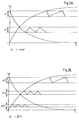
- FIG. 2a shows the behavior over time of the current I with a constant hysteresis ⁇ I.
- the current control with constant hysteresis works reliably as long as the set current is not in the order of magnitude of the set hysteresis ⁇ I. As soon as the current I is in the range of the hysteresis ⁇ I, an exact current control is no longer possible because the current has jump points.
- FIG. 2b shows the temporal behavior of the current I with variable hysteresis ⁇ I according to the circuit arrangement according to the invention.
- the case of a linear dependency between the hysteresis ⁇ I and the current I is shown.
- the hysteresis ⁇ I is chosen in the usual order of magnitude, it only being necessary to ensure that the permissible limit for the temperature increase associated with the switching losses the semiconductor valve is not exceeded.
- the proportionality between hysteresis ⁇ I and current I means that current regulation is still reliably possible even in the lower speed range, since the hysteresis ⁇ I always only makes up a fraction of the current I here.
Landscapes
- Engineering & Computer Science (AREA)
- Power Engineering (AREA)
- Control Of Motors That Do Not Use Commutators (AREA)
Applications Claiming Priority (2)
| Application Number | Priority Date | Filing Date | Title |
|---|---|---|---|
| DE4317044A DE4317044A1 (de) | 1993-05-21 | 1993-05-21 | Schaltungsanordnung für eine induktive Last |
| DE4317044 | 1993-05-21 |
Publications (2)
| Publication Number | Publication Date |
|---|---|
| EP0625821A2 true EP0625821A2 (fr) | 1994-11-23 |
| EP0625821A3 EP0625821A3 (fr) | 1995-05-17 |
Family
ID=6488652
Family Applications (1)
| Application Number | Title | Priority Date | Filing Date |
|---|---|---|---|
| EP94107451A Withdrawn EP0625821A3 (fr) | 1993-05-21 | 1994-05-13 | Circuit pour une charge inductive. |
Country Status (3)
| Country | Link |
|---|---|
| US (1) | US5579216A (fr) |
| EP (1) | EP0625821A3 (fr) |
| DE (1) | DE4317044A1 (fr) |
Cited By (1)
| Publication number | Priority date | Publication date | Assignee | Title |
|---|---|---|---|---|
| CN105827172A (zh) * | 2016-03-21 | 2016-08-03 | 广州中国科学院先进技术研究所 | 一种电-机械转换器的双模控制器 |
Families Citing this family (3)
| Publication number | Priority date | Publication date | Assignee | Title |
|---|---|---|---|---|
| DE19923508A1 (de) * | 1999-05-21 | 2000-11-23 | Rehm Gmbh U Co Schweistechnik | Verfahren und Vorrichtung zur Regelung einer elektrischen Stromquelle |
| US8975855B2 (en) | 2012-07-23 | 2015-03-10 | Caterpillar Inc. | Compensating hysteresis bands to hold specified switching frequency |
| DE102019127051A1 (de) | 2018-11-06 | 2020-05-07 | Elmos Semiconductor Aktiengesellschaft | Verfahren zur geräuschlosen, messpulsfreien Regelung der Kommutierung eines BLDC-Motors im Haltebetrieb |
Family Cites Families (16)
| Publication number | Priority date | Publication date | Assignee | Title |
|---|---|---|---|---|
| DE3017885C2 (de) * | 1980-05-09 | 1985-08-22 | Siemens AG, 1000 Berlin und 8000 München | Gleichstromversorgungseinrichtung |
| JPS5866584A (ja) * | 1981-10-12 | 1983-04-20 | Hitachi Ltd | 電流比較形交流電源装置 |
| JPS5914366A (ja) * | 1982-07-15 | 1984-01-25 | Hitachi Ltd | パルス幅変調インバ−タの制御方法 |
| CH662019A5 (de) * | 1982-08-11 | 1987-08-31 | Bbc Brown Boveri & Cie | Wechselrichteranordnung mit zweipulsigem wechselrichter mit einer vorrichtung zur toleranzbandsteuerung. |
| JPS5944975A (ja) * | 1982-09-03 | 1984-03-13 | Hitachi Ltd | Pwmインバ−タの制御方法および装置 |
| JPS61224894A (ja) * | 1985-03-29 | 1986-10-06 | Hitachi Ltd | 無刷子直流電動機 |
| IE851629L (en) * | 1985-06-28 | 1986-12-28 | Kollmorgen Ireland Ltd | Electrical drive systems |
| DE3602227A1 (de) * | 1986-01-25 | 1987-07-30 | Philips Patentverwaltung | Kommutierungsschaltung fuer einen kollektorlosen gleichstrommotor |
| US4743815A (en) * | 1987-09-01 | 1988-05-10 | Emerson Electric Co. | Brushless permanent magnet motor system |
| SU1642576A2 (ru) * | 1989-04-11 | 1991-04-15 | Предприятие П/Я Г-4832 | Реверсивный вентильный электродвигатель с регулируемым торможением |
| DE4120100A1 (de) * | 1990-06-28 | 1992-01-02 | Siemens Ag | Umrichteranordnung |
| DE4124240C2 (de) * | 1990-08-21 | 1994-08-04 | Heidelberger Druckmasch Ag | Verfahren zur Regelung des Motorstroms eines bürstenlosen Gleichstommotors |
| DE4026366A1 (de) * | 1990-08-21 | 1992-03-05 | Heidelberger Druckmasch Ag | Verfahren zur regelung des motorstroms eines buerstenlosen gleichstrommotors |
| US5159542A (en) * | 1991-11-04 | 1992-10-27 | Ford Motor Company | Selectable hysteresis controller for pulse width modulated inverter |
| US5499178A (en) * | 1991-12-16 | 1996-03-12 | Regents Of The University Of Minnesota | System for reducing harmonics by harmonic current injection |
| DE4324150C1 (de) * | 1993-07-19 | 1994-10-27 | Bruker Analytische Messtechnik | Feingeregeltes verlustarmes Hochleistungsnetzgerät |
-
1993
- 1993-05-21 DE DE4317044A patent/DE4317044A1/de not_active Ceased
-
1994
- 1994-05-13 EP EP94107451A patent/EP0625821A3/fr not_active Withdrawn
-
1996
- 1996-02-20 US US08/603,387 patent/US5579216A/en not_active Expired - Fee Related
Cited By (1)
| Publication number | Priority date | Publication date | Assignee | Title |
|---|---|---|---|---|
| CN105827172A (zh) * | 2016-03-21 | 2016-08-03 | 广州中国科学院先进技术研究所 | 一种电-机械转换器的双模控制器 |
Also Published As
| Publication number | Publication date |
|---|---|
| US5579216A (en) | 1996-11-26 |
| EP0625821A3 (fr) | 1995-05-17 |
| DE4317044A1 (de) | 1994-11-24 |
Similar Documents
| Publication | Publication Date | Title |
|---|---|---|
| DE4124240C2 (de) | Verfahren zur Regelung des Motorstroms eines bürstenlosen Gleichstommotors | |
| EP1305876B1 (fr) | Procede pour reguler une machine electrique au moyen d'un onduleur pulse | |
| WO1999006241A1 (fr) | Procede pour reguler un generateur pouvant etre entraine par un moteur a combustion interne | |
| DE4031398A1 (de) | Verfahren und schaltung zur regelung der drehgeschwindigkeit eines gleichstrommotors | |
| DE102019127051A1 (de) | Verfahren zur geräuschlosen, messpulsfreien Regelung der Kommutierung eines BLDC-Motors im Haltebetrieb | |
| EP1087513A2 (fr) | Convertisseur de fréquence pour un moteur électrique | |
| DE112008003579T5 (de) | Motorantriebssteuervorrichtung | |
| EP0662266B1 (fr) | Procede et dispositif de regulation d'un moteur synchrone a excitation continue alimente par un convertisseur | |
| EP0935336B1 (fr) | Méthode et dispositif de commande d' un moteur synchron | |
| EP0714162B1 (fr) | Circuit de commande d'une moteur commuté électroniquement | |
| EP0625821A2 (fr) | Circuit pour une charge inductive | |
| DE69803885T2 (de) | Steuerungsvorrichtung für elektrische motoren | |
| DE4026366C2 (fr) | ||
| DE10219821A1 (de) | Verfahren und Vorrichtung zur Regelung einer permanentmagneterregten Synchronmaschine mit reduzierten Leistungspendelungen im oberen Drehzahlbereich | |
| DE2414721C3 (de) | Verfahren zur Steuerung der Drehzahl- bzw. Geschwindigkeit einer frequenzumrichtergespeisten Drehstrom-Asynchronmaschine | |
| DE3409299C2 (de) | Ein- oder mehrphasiger Wechselstromsteller mit Impulsbreitensteuerung | |
| DE102009001507A1 (de) | Verfahren zum Betrieb eines elektrischen Servolenksystems und danach arbeitendes Steuergerät | |
| EP0456854B1 (fr) | Procédé et dispositif pour la régulation d'un onduleur d'impulsion triphasé | |
| DE2238627C3 (de) | Bürstenloser Gleichstrommotor | |
| EP1293033B1 (fr) | Commande et regulation de moteurs electriques | |
| DE4310772A1 (de) | Reluktanzmotor als Servoantrieb | |
| DE2731503C2 (de) | Schaltungsanordnung zur Zweizonen-Drehzahlregelung eines Gleichstrommotors mit abhängiger Feldsteuerung des Motors | |
| DE10002706A1 (de) | Verfahren zur Steuerung der Umrichterschaltung einer geschalteten Reluktanzmaschine | |
| EP1063762B1 (fr) | Méthode de positionnement d'un moteur pas-à-pas et entraínement électrique | |
| DE10122295B4 (de) | Verfahren zur Regelung und Umrichter zur Durchführung des Verfahrens |
Legal Events
| Date | Code | Title | Description |
|---|---|---|---|
| PUAI | Public reference made under article 153(3) epc to a published international application that has entered the european phase |
Free format text: ORIGINAL CODE: 0009012 |
|
| 17P | Request for examination filed |
Effective date: 19940513 |
|
| AK | Designated contracting states |
Kind code of ref document: A2 Designated state(s): CH DE FR GB IT LI |
|
| GBC | Gb: translation of claims filed (gb section 78(7)/1977) | ||
| PUAL | Search report despatched |
Free format text: ORIGINAL CODE: 0009013 |
|
| AK | Designated contracting states |
Kind code of ref document: A3 Designated state(s): CH DE FR GB IT LI |
|
| 17Q | First examination report despatched |
Effective date: 19970904 |
|
| STAA | Information on the status of an ep patent application or granted ep patent |
Free format text: STATUS: THE APPLICATION IS DEEMED TO BE WITHDRAWN |
|
| 18D | Application deemed to be withdrawn |
Effective date: 19980317 |