EP0627741B1 - Dispositif de mémoire à semiconducteurs - Google Patents
Dispositif de mémoire à semiconducteurs Download PDFInfo
- Publication number
- EP0627741B1 EP0627741B1 EP94105502A EP94105502A EP0627741B1 EP 0627741 B1 EP0627741 B1 EP 0627741B1 EP 94105502 A EP94105502 A EP 94105502A EP 94105502 A EP94105502 A EP 94105502A EP 0627741 B1 EP0627741 B1 EP 0627741B1
- Authority
- EP
- European Patent Office
- Prior art keywords
- bit line
- coupled
- capacitor
- adjusting
- ferroelectric
- Prior art date
- Legal status (The legal status is an assumption and is not a legal conclusion. Google has not performed a legal analysis and makes no representation as to the accuracy of the status listed.)
- Expired - Lifetime
Links
Images


Classifications
-
- G—PHYSICS
- G11—INFORMATION STORAGE
- G11C—STATIC STORES
- G11C11/00—Digital stores characterised by the use of particular electric or magnetic storage elements; Storage elements therefor
- G11C11/21—Digital stores characterised by the use of particular electric or magnetic storage elements; Storage elements therefor using electric elements
- G11C11/22—Digital stores characterised by the use of particular electric or magnetic storage elements; Storage elements therefor using electric elements using ferroelectric elements
Definitions
- This invention relates to a semiconductor memory device having memory cells formed with ferroelectric capacitors.
- a dynamic random access memory (DRAM) that a data is stored in a memory cell capacitor thereof is generally known as one of semiconductor memory cell devices.
- a silicon oxide film is conventionally used as an insulating film of the memory cell capacitor.
- This semiconductor memory device comprises, as basic components, a memory cell having a MOS transistor and a ferroelectric capacitor, a pair of bit lines coupled to the memory cell, a word line coupled to the memory cell, a plate line coupled to the memory cell, and a sense amplifier coupled to the pair of bit lines.
- the MOS transistor of the memory cell is coupled to the bit lines while the ferroelectric capacitor is coupled between the MOS transistor and the plate line.
- Writing of data in this semiconductor memory device is performed by the method which consists in applying a reverse logical voltage to the ferroelectric capacitor of the memory cell. Reading of data is made by the method which consists in taking out electric charge stored in the ferroelectric capacitor from the pair of bit lines as potential and amplifying the potential difference between those bit lines with the sense amplifier.
- a prior semiconductor memory device (EP0 486 902 A3) as indicated in the precharacterizing parts of claims 1 and 10 has the adjusting capacitors for adjusting the bit line capacitance in preamplifiers which are coupled between a bit line and the corresponding sense amplifier. Then in this prior art memory device at a first step, data (electric charge) read out from ferroelectric capacitors to a bit line are stored in the plurality of adjusting capacitors connected in parallel to the bit line. At a second step, all capacitors are disconnected from the bit line by switching off transistors, and then all capacitors are connected in series by switching on additional transistors, thereby the potential difference between the potential of the bit line and that of a reference voltage is increased. The resulting increased potential difference enables reliable read out of the data stored in the ferroelectric capacitors through the sense amplifier. Therefore, this prior art memory device needs transistors as switching elements between the bit and the adjusting capacitors.
- a semiconductor memory device of the invention comprises, as basic components, a bit line, a word line, a plate electrode, a ferroelectric capacitor having a first electrode and a second electrode, this second electrode being coupled to the plate electrode, a MOS transistor the source of which is coupled to the first electrode of the ferroelectric capacitor and the gate of which is coupled to the word line, and an adjusting capacitor coupled between the bit line and a signal line for adjusting the capacitance of the bit line.
- Bit line BL0 and bit line /BL0 are coupled to sense amplifier SA0 while bit line BL1 and bit line /BL1 are coupled to sense amplifier SA1.
- the operation of sense amplifiers SA0, SA1 is controlled by sense amplifier control signal SAE supplied from line L4.
- First electrode of ferroelectric capacitor Cs00 of the memory cell is coupled to bit line BL0 through N-charimel type MOS transistor Qn00.
- Second electrode of capacitor Cs00 is coupled to cell plate electrode CP0.
- First electrode of ferroelectric capacitor Cs00B of the memory cell is coupled to bit line /BL0 through N-channel type MOS transistor Qn00B.
- second electrode of capacitor Cs00B is coupled to cell plate electrode CP0.
- respective first electrodes of ferroelectric capacitors Cs01-Cs07 of the memory cell are coupled to bit line BL0 through N-channel type MOS transistors Qn01-Qn07.
- respective second electrodes of capacitors Cs01-Cs07 are coupled respectively to cell plate electrodes CP1-CP7.
- respective first electrodes of ferroelectric capacitors Cs01B-Cs07B are coupled to bit line /BL0 through N-channel type MOS transistors Qn01B-Qn07B.
- respective second electrodes of capacitors Cs01B-Cs07B are coupled respectively to cell plate electrodes CP1-CP7.
- Ferroelectric capacitors Cs10-Cs17 and ferroelectric capacitors Cs10B-Cs17B of another column are coupled respectively to bit line BL1 and bit line /BL1 so that the data may be read out in the same way as above.
- MOS transistors Qn01L, Qn02L, Qn02LB are coupled between a pair of bit line BL0 and bit line /BL0 and line L2 supplying equalizing signal and precharge control signal EQ to the bit lines.
- MOS transistors Qn11L, Qn12L, Qn12LB are coupled between a pair of bit line BL1 and bit line /BL1 and line L2.
- MOS transistors Qn02L, Qn02LB, Qn12L, Qn12LB are coupled to line L3 with a ground voltage VSS.
- the precharge potential is equal to the ground voltage.
- bit lines BL0, /BL0, BL1, /BL1 electrodes on one side of adjusting capacitors Cb0, Cb0B, Cb1, Cb1B for adjusting a bit line capacitance are coupled respectively.
- the other electrodes of those adjusting capacitors Cb0, Cb0B, Cb1, Cb1B are coupled to line L1 supplying the supply voltage VOC.
- the voltage applied to those electrodes coupled to line L1 can be set optionally.
- Adjusting capacitors Cb0, Cb0B, Cb1, Cb1B are realized by forming a plate electrode of polysilicon on and under the insulating film of silicon oxide.
- adjusting capacitors Cb0, Cb0B, Cb1, Cb1B can be formed in a variety of ways with a construction utilizing the gate insulating film of a MOS transistor or utilizing the capacitance against a sub-plate by increasing the length of a bit line, etc.
- Fig. 3 explains the hysteresis characteristics of the ferroelectric material.
- the horizontal axis indicates the electric field applied to the ferroelectric capacitor of the memory cell while the virtical axis represents the electric charge at that time.
- residual polarization indicated with point B and point E remains even when the electric field is zero. Therefore, a nonvolatile semiconductor memory device is realized by utilizing the residual polarization remaining in the ferroelectric capacitor as nonvolatile data even if the power supply is interrupted.
- bit lines BL0, /BL0, word lines WL0-WL7, cell plate electrodes CP0-CP7 and line L4 supplying control signal SAE are settled to logical voltage "L” (low voltage) and line L2 supplying control signal EQ are settled to logical voltage "H” (high voltage) to read out the data in the memory data. If, after that, line L2 is settled to "L", bit lines BL0, /BL0 get in a floating state.
- Line l 1 has an inclination dependent on the value of the bit line capacitance equal to the sum of the parasitic capacitance of bit line BL0 and the capacitance of adjusting capacitor Cb0.
- Line l 2 has an inclination dependent on the value of the bit line capacitance equal to the sum of the parasitic capacitance of bit line /BL0 and the capacitance of adjusting capacitor Cb0B.
- the absolute value of the inclination of line l I and line l 2 diminishes as the capacitance value becomes smaller.
- Point 03 is the point of intersection of the hysteresis curve of capacitor Cs00 moving from point B to point D when an electric field is applied to capacitor Cs00 and the line l 1 passing through point M3.
- point M3 is a point moved from point B to the direction of the horizontal axis by a quantity corresponding to the electric field produced when the voltages of word line WL0 and cell plate electrode CP0 are changed to "H".
- Point P3 is the point of intersection of the hysteresis curve moving from point E to point D when an electric field is applied to capacitor Cs00B and line l 2 passing through point N3.
- point N3 is a point moved from point E to the direction of the horizontal axis by a quantity corresponding to the electric field produced when the voltages of word line WL0 and cell plate electrode CP0 are changed to logical voltage "H".
- the potential difference read out between bit line BL0 and bit line /BL0 here is the potential difference Vr3 which is the difference between point 03 and point P3.
- Vr3 the potential difference between point 03 and point P3.
- bit line BL0 moves from point Q3 to point A while the state of bit line /BL0 moves from point D to point E.
- the voltages of word line WL0 and line L4 are changed to "L” and control signal EQ of line L2 is changed to "H”.
- bit line BL0 and bit line /BL0 are settled to "L” to return to the initial state.
- bit line capacitance equal to the sum of the parasitic capacitance of the bit line and the capacitance of the adjusting capacitor i.e. the inclination of lines l 1, l 2 is determined in a way to satisfy that requirement.
- the capacitance value of the adjusting capacitor is decided in such a way that the potential difference obtained by dividing the electric charge read out from capacitor Cs00 by the total capacitance of the bit lines (sum of the parasitic capacitance of the bit line, the capacitance of the adjusting capacitor and the capacitance of the ferroelectric capacitor) may be not less than the minimum operating voltage of the sense amplifier.
- the capacitance of the adjusting capacitor in a way to increase potential difference Vr3 as much as possible, more accurate and high-speed amplification by sense amplifier becomes possible.
- the sense amplifier used for DRAM its potential difference is settled to no less than approximately 50 mV.
- the device is designed to have the maximum potential difference Vr3 to operate at low voltage.
- the potential difference is settled to approximately 100 mV in a 256K-bit semiconductor memory device with 1-capacitor memory cell type and at approximately 1200 mV in a 1K-bit semiconductor memory device with 2-capacitor memory cell type.
- Fig. 1 and Fig. 2 The circuit construction and the operating timing chart of the second embodiment are indicated in Fig. 1 and Fig. 2 in the same way as for the first embodiment.
- Fig. 4 indicates the relation between the hysteresis characteristics of the ferroelectric material used for the ferroelectric capacitor of the memory cell and the data reading operation of the memory cell in this embodiment.
- bit line capacitance value equal to the sum of the parasitic capacitance of the bit line and the capacitance of the adjusting capacitor is smaller than that in the first embodiment.
- the absolute value of the inclination of lines l 1, l 2 in Fig. 4 is smaller than the value indicated in Fig. 3.
- the potential difference read out between bit line BL0 and bit line /BL0 here is the potential difference Vr4.
- the potential difference Vr4 must be of a value accurately amplifiable with sense amplifier SA0.
- Fig.5 illustrates the relation between the bit line capacitance value Cb equal to the sum of the parasitic capacitance of the bit line and the capacitance of the adjusting capacitor and the potential difference Vr read out between bit line BL0 and bit line /BL0.
- the potential difference Vr is expressed with a curve having the maximum value against the bit line capacitance value Cb.
- the potential difference Vrm indicates the minimum value accurately amplifiable with the sense amplifier and readable.
- the second embodiment provides a smaller bit line capacitance value Cb. Namely, the absolute value of the inclination of lines l1, l2 is smaller. For that reason, in the reading operation made when the data of the memory cell is "1", while the condition of the memory cell changes from the state of point B to the state of point 03 in Fig. 3 in the first embodiment, it changes from the state of point B to point 04 in Fig. 4 in the second embodiment.
- the electric field applied to the ferroelectric material constituting the memory cell is smaller in the second embodiment. Namely, the ferroelectric material is subject to less deterioration because the rate of reversion of the polarization of ferroelectric material is lower. In this way, the smaller the bit line capacitance value Cb to be used between Cb l and Cbh, the smaller the deterioration of the ferroelectric material and longer the life of the memory cell.
- Fig. 1 and Fig. 2 The circuit construction and the operating timing chart of the third embodiment are indicated in Fig. 1 and Fig. 2 in the same way as for the first embodiment.
- Fig. 6 represents the relation between the hysteresis characteristics of the ferroelectric material used for the ferroelectric capacitor of the memory cell and the data reading operation of the memory cell in the third embodiment.
- This third embodiment differs from the first embodiment in that a barium titanate based ferroelectric material is used for adjusting capacitors Cb0, Cb0B, Cb1, Cb1B for adjusting the bit line capacitance.
- a barium titanate based ferroelectric material for the adjusting capacitors, it becomes possible to obtain a larger capacitance value with a smaller surface area compared with adjusting capacitors realized by using an oxide film other than ferroelectric material such as silicon oxide film, etc.
- the potential in the standby state of the bit line is given as ground voltage VSS and the electrode on the side not coupled to the bit line of the adjusting capacitor is given as supply voltage VCC.
- the lines l 1, l 2 in Fig. 6 indicating the capacitance value of the bit line from curves which are convex on the upper side because the potential of the electrode of the adjusting capacitors changes from the supply voltage VCC toward the ground voltage VSS.
- the potential difference read out between bit line BL0 and bit line /BL0 here is the potential difference Vr6 in the same way as in embodiment 1 and embodiment 2.
- a ferroelectric material is used for the adjusting capacitors.
- the potential of the first electrode coupled to the bit line (ground voltage VSS in the standby state) and the potential of the second electrode coupled to the supply voltage VCC (to be applied) to the two electrodes of the adjusting capacitors are reversed with each other. By so doing, it becomes possible to initialize the capacitance value of the capacitors using a ferroelectric material.
- the ground voltage VSS is applied to the electrode on one side (electrode coupled to the bit line) and the supply voltage VCC is applied to the plate (i.e. electrode on the side opposite to the electrode coupled to the bit line) in the standby state.
- the same effect can be obtained even in the contrary case i.e. when the supply voltage VCC is applied to the electrode coupled to the bit line and the ground voltage VSS is applied to the plate electrode.
- This embodiment indicates a case where a barium titanate based ferroelectric material is used for the adjusting capacitors.
- oxides having perovskite structure such as lead titanate, barium zirconate, lead zirconate, etc. and other oxides in which part of the metal component elements of such oxides are replaced with other elements.
- ferroelectric materials not having any perovskite structure such as lead niobate, etc.
- ferroelectric material of adjusting capacitors it is desirable to use a ferroelectric material of the same base as the material of the ferroelectric capacitors of the memory cell, because it enables to manufacture the adjusting capacitors and the ferroelectric capacitors in one same manufacturing process and simplify the manufacturing process.
- the adjusting capacitors and the ferroelectric capacitors are not much different in shape and size from each other.
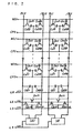
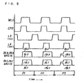
- Fig. 7 represents the circuit construction of the fourth embodiment while Fig. 8 illustrates its operating timing chart.
- Fig. 9 indicates the relation between the hysteresis characteristics of the ferroelectric material used for the ferroelectric capacitor of the memory cell and the data reading operation of the memory cell in the fourth embodiment.
- this fourth embodiment differs from the first embodiment in that a ferroelectric material is used for the adjusting capacitors Cb0F, Cb0BF, Cb1F, Cb1BF for adjusting the bit line capacitance and that the electrode coupled to those bit lines is coupled to line L5 which has the ground voltage VSS.
- the state of polarization of adjusting capacitors Cb0F, Cb0BF, Cb1F, Cb1BF is indeterminate and their capacitance values are not initialized immediately after its manufacture. It is therefore necessary to initialize the state of polarization of the adjusting capacitors against such state immediately after the manufacture.
- bit lines BL1, /BL1 As a method for such initialization, one makes a writing operation of providing bit line /BL0 with a logical voltage "H" during the period p1 to initialize adjusting capacitor Cb0F. One also makes a writing operation of providing bit line BL0 with a logical voltage "H” during the period p2 to initialize adjusting capacitor Cb0BF. The same is true with bit lines BL1, /BL1 as well. This initialization is enough if one makes it only once after the manufacture of the semiconductor memory device.
- the period p3 in Fig. 8 indicates the period of reading operation.
- the lines l 1, l 2 corresponding to the capacitance value of the bit line form curves which are convex on the lower side because the potential of the bit line in the standby state has the ground voltage VSS and the potential of the electrode opposite to the electrode coupled to the bit lines has the ground voltage VSS.
- the potential difference read out between bit line BL0 and bit line /BL0 is the potential difference Vr9 in the same way as in emboidment 1 and embodiment 2.
- no further initialization is required if one makes it once immediately after the manufacture of the semiconductor memory device as in the case of embodiment 3.
- the two electrodes of adjusting capacitors Cb0F, Cb0BF are in the standby state i.e. have the ground voltage VSS. For that reason, there is no need of storing any electric charge in adjusting capacitor Cb0F, Cb0BF especially at the time of power-on, etc. This helps to reduce the electric power consumption at the time of power-on.
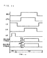
- Fig. 10 indicates the circuit construction of the fifth embodiment while Fig. 11 illustrates its operating timing chart.
- the drawing indicating the relation between the hysteresis characteristics of the ferroelectric material uesd for the ferrorlectric capacitor of the memory cell and the data reading operation of the memory cell is the same as that in Fig. 9 of the fourth embodiment.
- the circuit construction drawing of Fig. 10 differs from that of the fourth embodiment in Fig. 7 in that, while the line L3 has the ground voltage VSS in the fourth embodiment, the line L6 corresponding to it has a variable potential VBE in this fifth embodiment.
- one provides line L2 and line 6 with an operation of acquiring the logical voltage "H" for the period p4 so that voltages of bit lines BL0, /BL0, BL1, /BL1 are set at "H”. Adjusting capacitors Cb0F, Cb0BF, Cb1F, Cb1FB are initialized by this method. This initialization is enough if one makes it only once after the manufacture of the semiconductor memory device.
- the period p5 here indicates the period of reading operation.
- the relation between the hysteresis characteristics of the ferroelectric material used for the ferroelectric capacitor and the data reading operation of the memory cell is the same as that in the fourth embodiment.
- the initialization of the state of polarization of the adjusting capacitors can be performed at a time by providing the line L6 with a variable potential VBE.
- both of the two electrodes of the adjusting capacitors have the ground voltage VSS in the standby state. For that reason, there is no need of storing any electric charge in the adjusting capacitor especially at the time of power-on, etc. This helps to reduce the electric power consumption at the time of power-on.
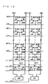
- Fig. 12 represents the circuit construction of the this sixth embodiment.
- Fig. 2 is used in the same way as in the third embodiment.
- the relation between the hysteresis characteristics of the ferroelectric material used for the ferroelectric capacitor of the memory cell and the data reading operation of the memory cell is also represented by Fig. 6 as in the third embodiment.
- This sixth embodiment differs from the third embodiment in that the adjusting capacitors using ferroelectric material are split into a plurality of pieces as represented by a pair of adjusting capacitors Cb00F, Cb01F, a pair of adjusting capacitors Cb00BF, Cb01BF, a pair of adjusting capacitors Cb10F, Cb11F and a pair of adjusting capacitors Cb10BF, Cb11BF. Moreover, it is desirable that the respective adjusting capacitors split into a plurality of pieces have a capacitance value about equal to that of the ferroelectric capacitors of the memory cell.
- the capacitance value of the adjusting capacitors By thus setting the capacitance value of the adjusting capacitors about equal to that of the ferroelectric capacitors of the memory cell and constructing the adjusting capacitors in a plurality of pieces, it becomes possible to maintain the relative value between the change in the capacitance value of the ferroelectric capacitors and the change in the capacitance value of the adjusting capacitors almost unchanged even in the case of a change in the capacitance value of the adjusting capacitors using a ferroelectric material. For that reason, the potential difference Vr6 read out between bit line BL0 and bit line /BL0 can be maintained at a level accurately amplifiable with the sense amplifier SA0. Moreover, by forming the adjusting capacitors and the ferroelectric capacitors of the memory cell in about the shape and the size, it becomes possible to further simplify their manufacturing process.
- Fig. 13 represents the circuit construction of the seventh embodiment.
- the operating timing chart is indicated in Fig. 2 in the same way as in the third embodiment.
- the drawing showing the relation between the hysteresis characteristics of the ferroelectric material used for the ferroelectric capacitor of the memory cell and the data reading operation of the memory cell is also given in Fig. 6 as in the third embodiment.
- This seventh embodiment differs from the third embodiment in that the adjusting capacitors using ferroelectric material are split into a plurality of pieces as represented by a pair of adjusting capacitors Cb00F, Cb01F, a pair of adjusting capacitors Cb00BF, Cb01BF, a pair of adjusting capacitors Cb10F, Cb11F and a pair of adjusting capacitors Cb10BF, Cb11BF.
- the adjusting capacitors Cb01F, Cb01BF, Cb11F, Cb11BF are coupled to the bit lines BL0, /BL0, BL1, /BL1 respectively through N-channel type MOS transistor Qn03L, Qn03LB, Qn13L, Qn13LB.
- the gate of each N-channel type MOS transistor Qn03L, Qn03LB, Qn13L, Qn13LB is coupled to the line L7 feeding the control signal CBC for adjusting the bit line capacitance.
- the adjusting capacitors Cb01F, Cb01BF, Cb11F, Cb11BF can be electrically cut from each bit line. This makes it possible to change the capacitance value of the adjusting capacitors easily, i.e. reduce the capacitance value in this case. Therefore, by controlling the control signal CBC, it becomes possible to control the potential difference Vr6 read out between bit line BL0 and bit line /BL0 at a voltage level accurately amplifiable with sense amplifier SA0.
- the adjustment of the capacitance value of the adjusting capacitors can also be made with the use of a physical separating means such as cutting the line in the neighborhood of the adjusting capacitors with laser beam, etc. in addition to the electrical means of switching off by MOS transistor.
- Fig. 14 represents the circuit construction of the eighth embodiment.
- the operating timing chart is illustrated in Fig. 2 in the same way as for the first embodiment.
- the drawing indicating the relation between the hysteresis characteristics of the ferroelectric material used for the ferroelectric capacitor of the memory cell and the data reading operation of the memory cell is given in Fig. 3 in the same way as for the first embodiment.
- This eighth embodiment differs from the first embodiment in that cell plate electrodes CP0, CP1 coupled to the memory cells are arranged in parallel with bit lines BL0, /BL0, BL1, /BL1.
- Sense amplifier SA0 coupled to line L40 is coupled to bit line BL0, /BL0, and sense amplifier SA1 coupled to line L41 is coupled to bit line BL1, /BL1.
- the memory cell data can be read from only selected memory cell. Namely, the data is read out only from the memory cell positioned at the point of intersection between the word line having the logical voltage "H" and the cell plate electrode having the logical voltage "H". For that reason, sense amplifiers SA0, SA1 are controlled by two signals i.e.
- control signal SAE0 fed by line L40 and control signal SAE1 fed by line L41 to sense amplifiers SA0, SA1 respectively.
- the construction in which adjusting capacitors Cb0, Cb0B, Cb1, Cb1B are coupled to the bit line and the effects of that construction are the same as those in the first embodiment.
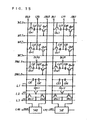
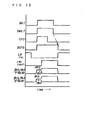
- Fig. 15 represents the circuit construction of the ninth embodiment while Fig. 16 illustrates its operating timing chart.
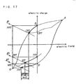
- Fig. 17 indicates the relation between the hysteresis characteristics of the ferroelectric material used for the ferroelectric capacitor of the memory cell and the data reading operation of the memory cell.
- one memory cell is constituted by one ferroelectric capacitor and one MOS transistor in the ninth embodiment while it consists of two ferroelectric capacitors and two MOS transistors in the first embodiment.
- this semiconductor memory device is composed of word lines WL0-WL3, dummy word lines DWL0-DWL1, bit lines BL0, /BL0, BL1, /BL1, cell plates electrodes CP0, CP1, dummy cell plates electrodes DCP0, DCP1, line L2 feeding equalizing signal and precharge control signal EQ for bit lines, line L40 and line L41 feeding sense amplifier control signals SAE0, SAE1 to sense amplifiers SA0, SA1, ferroelectric capacitors Cs1-Cs8 of memory cell, dummy ferroelectric capacitors Cd1-Cd4, N-channel type MOS transistors Qn1-Qn8, Qnd1-Qnd4, QnL1-QnL6 and adjusting capacitors Cb1, Cb2, Cb3, Cb4.
- One memory cell is constituted, for example, by a ferroelectric capacitor Cs1 and a MOS transistor Qnd1 the gate of which is coupled to word line WL0. And the first electrode of ferroelectric capacitor Cs1 is coupled to the source of MOS transistor Qn1. The second electrode of ferroelectric capacitor Cs1 is coupled to cell plate electrode CP0. Moreover, the drain of MOS transistor Qn1 is coupled to bit line BL0. Other memory cells are also constructed in the same way.
- the dummy memory cells are also composed of a dummy ferroelectric capacitor Cd1 and a MOS transistor Qnd1 the gate of which is coupled to dummy word line DWL0.
- the first electrode of ferroelectric capacitor Cd1 is coupled to the source of MOS transistor Qnd1.
- the second electrode of ferroelectric capacitor Cdl is coupled to dummy cell plate electrode DCP0.
- the drain of MOS transistor Qnd1 is coupled to the bit line BL0.
- Other dummy memory cells are also constructed in the same way.
- the electrode on one side of adjusting capacitors Cb1, Cb2, Cb3, Cb4 is coupled to each of bit lines BL0, /BL0, BL1, /BL1 and the electrode on the other side is coupled to line L1 having the supply voltage VCC.
- the voltage of the electrode coupled to line L1 can be set optionally.
- bit lines BL0, /BL0 and a pair of bit lines BL1, /BL1 are coupled respectively to sense amplifiers SA0, SA1.
- Sense amplifiers SA0, SA1 are controlled respectively by the sense amplifier control signals SAE0, SAE1 and operate respectively when sense amplifier control signals SAE0, SAE1 have the logical voltage "H".
- bit line BL0 and bit line /BL0 are coupled each other through MOS transistor QnL1
- bit line BL1 and bit line /BL1 are coupled each other through MOS transistor QnL2.
- bit line BL0 and bit line /BL0 are coupled each other through MOS transistors QnL3, QnL4, and bit line BL1 and bit line /BL1 are coupled each other through MOS transistors QnL5, QnL6.
- the gates of MOS transistors QnL1-QnL6 are coupled to line L2.
- word line WL1, dummy word line DWL1, cell plate electrode CP1 and dummy cell plate electrode DCP1 are all settled to "H".
- the data of the dummy memory cell is read out on bit line BL0 and the data of the memory cell is read out on bit line /BL0. If, at that time, the data of the memory cell is "1", the condition of the memory cell changes from the state of point B to the state of point 017 in Fig, 17. If the data of the memory cell is "0", the condition of the memory cell changes from the state of point E to the state of point P17 and that of the dummy memory cell changes from the state of point T17 to the state of point S17.
- the data read out on bit lines BL0, /BL0 is amplified. If the data of the memory cell is "1" in the state where the data is amplified with an operation of the sense amplifier, the condition of the memory cell changes from the state of point 017 to the state of point Q17 and that of the dummy memory cell changes from the state of point S17 to the state of point P17. If, at this time, the data of the memory cell is "0", the condition of the memory cell changes from the state of point P17 to the state of point D and that of the dummy memory cell changes from the state of point S17 to the state of point T17.
- cell plate electrode CP0 is settled to logical voltage "L". If, at that time, the data of the memory cell is "1", the condition of the memory cell changes from the state of point Q17 to the state of point A and that of the dummy memory cell maintains the state of point D. If the data of the memory cell is "0”, the condition of the memory cell moves from the state of point D to the state of point E and that of the dummy memory maintains the state of point T17.
- word line WL1 and dummy word lines DWL1 are settled to "L". If, at that time, the data of the dummy cell is "1", the condition of the memory cell changes from the state of point A to the state between point A and point B and that of the dummy memory cell changes from the state of point D to the state between point D and point T17. After that, the condition of the dummy memory cell is placed in the state of point T17. If the data of the memory cell is "0", the condition of the memory cell maintains the state of point E while that of the dummy memory cell maintains the state of point T17.
- dummy cell plate electrode DCP0 is settled to "L”
- line L40 is settled to “L”
- line L2 is settled to "H”
- bit lines BL0, /BL0 are settled to “L” respectively.
- the capacitance value of the bit lines is determined from the capacitance value equal to the sum of the parasitic capacitance of the bit lines and the capacitance of the adjusting capacitors.
- This capacitance value of the bit lines decides the inclination of lines l 1, l 2, l 3.
- the inclination of lines l 1, l 2, l 3 shall preferably be decided in such a way that the reading potential difference Vr17 of the data "1" and the data "0" of the memory cell may be at least twice as large as the potential difference accurately amplifiable with the sense amplifier.
- the capacitance value of the adjusting capacitor shall preferably be decided so as to satisfy the above condition.
- point S17 the point of intersection of the curve indicating the capacitance of the dummy memory cell i.e. the line passing through points D, T17 and the line l 3 passing through point R17 is designated as point S17.
- point R17 is a point moved from point T17 to the direction of the horizontal axis by a quantity corresponding to the electric field produced immediately after word line WL0 and cell plate electrode CP0 are brought to logical voltage "H".
- Line l 3 passing through point R17 is a line obtained by displacing the lines l 1, l 2 in parallel.
Landscapes
- Engineering & Computer Science (AREA)
- Computer Hardware Design (AREA)
- Dram (AREA)
Claims (11)
- Dispositif de mémoire à semiconducteur comprenant :caractérisé en ce queune première ligne de bit (BL0) et une seconde ligne de bit (/BL0) formant une paire,une ligne de mots (WL0),une électrode de plaque, (CP0),un condensateur ferroélectrique (Cs00) comportant une première électrode et une seconde électrode, ladite seconde électrode étant reliée à ladite électrode de plaque (CP0),un transistor de type MOS (Qn00) dont la source est reliée à ladite première électrode, la grille est reliée à ladite ligne de mots (WL0) et le drain est relié à ladite première ligne de bit (BL0),un condensateur de réglage (Cb0) destiné à ajuster la capacité de la ligne de bit, etun amplificateur de lecture (SA0) auquel sont reliées ladite première ligne de bit (BL0) et une seconde ligne de bit (/BL0),
ledit condensateur de réglage (Cb0) est relié entre ladite première ligne de bit (BL0) et une ligne de signal (L1) où ledit condensateur de réglage (Cb0) présente une valeur de capacité définie de telle manière qu'une différence de potentiel entre un potentiel de lecture de ladite première ligne de bit (BL0) et un potentiel de lecture de ladite seconde ligne de bit (/BL0) ne soit pas inférieure à une tension de service minimum dudit amplificateur de lecture (SA0). - Dispositif de mémoire à semiconducteur selon la revendication 1, dans lequel ledit condensateur de réglage est constitué d'une paire comprenant un premier condensateur de réglage (Cb0) et un second condensateur de réglage (Cb0B), ledit premier condensateur de réglage étant relié à ladite première ligne de bit, ledit second condensateur de réglage étant relié à ladite seconde ligne de bit.
- Dispositif de mémoire à semiconducteur selon la revendication 2, dans lequel ledit premier condensateur de réglage et ledit second condensateur de réglage sont constitués d'une pluralité de condensateurs (Cb00F, Cb01F) respectivement.
- Dispositif de mémoire à semiconducteur selon la revendication 3, dans lequel chaque condensateur de ladite pluralité de condensateurs (Cb00F, Cb01F) présente une valeur de capacité environ égale à celle dudit condensateur ferroélectrique (Cs00).
- Dispositif de mémoire à semiconducteur selon la revendication 3, dans lequel un moyen de séparation est prévu entre au moins un' condensateur de ladite pluralité de condensateurs (Cb00F, Cb01F) et au moins l'une desdites première et seconde lignes de bit.
- Dispositif de mémoire à semiconducteur selon la revendication 2, dans lequel ledit premier condensateur de réglage et ledit second condensateur de réglage comprennent un film ferroélectrique.
- Dispositif de mémoire à semiconducteur selon la revendication 1, dans lequel ladite valeur de capacité est la valeur minimum.
- Dispositif de mémoire à semiconducteur selon la revendication 6, dans lequel le système constitutif d'un matériau dudit film ferroélectrique est identique à celui d'un matériau dudit condensateur ferroélectrique.
- Dispositif de mémoire à semiconducteur selon la revendication 6, dans lequel une forme et une taille desdits premier et second condensateurs d'ajustage sont environ les mêmes qu'une forme et une taille dudit condensateur ferroélectrique.
- Dispositif de mémoire à semiconducteur comprenant :caractérisé en ce queune première ligne de bit (BL0) et une seconde ligne de bit (/BL0) formant une paire,une première ligne de mots (WL0) et une seconde ligne de mots (DWL0) formant une paire,une première électrode de plaque (CP0) et une seconde électrode de plaque (DCP0) formant une paire,un premier condensateur ferroélectrique (Cs1) relié à ladite première électrode de plaque (CP0) et un second condensateur ferroélectrique (Cd2) relié à ladite seconde électrode de plaque (DCP0),un premier transistor de type MOS (Qn1) dont la source est reliée audit premier condensateur ferroélectrique (Cs1), la grille est reliée à ladite première ligne de mots (WL0) et le drain est relié à ladite première ligne de bit (BL0),un second transistor de type MOS (Qnd2) dont la source est reliée audit second condensateur ferroélectrique (Cd2), la grille est reliée à ladite seconde ligne de mots (DWL0) et le drain est relié à ladite seconde ligne de bit (/BL0),des premier et second condensateurs d'ajustage (Cb1, Cb2) destinés à ajuster la capacité de la ligne de bit, etun amplificateur de lecture (SA0) auquel sont reliées ladite première ligne de bit (BL0) et une seconde ligne de bit (/BL0),
une valeur de capacité dudit second condensateur ferroélectrique (Cd2) qui se trouve entre une valeur de capacité dudit premier condensateur ferroélectrique (Cs1) au moment où une tension logique à l'état haut "H" est écrite dans ledit premier condensateur ferroélectrique (Cs1) et une valeur de capacité dudit premier condensateur ferroélectrique (Cs1) au moment où une tension logique à l'état bas "L" est écrite dans ledit premier condensateur ferroélectrique (Cs1), et
ledit premier condensateur de réglage (Cb1) est relié entre ladite première ligne de bit (BL0) et une ligne de signal (L1), et
ledit second condensateur de réglage (Cb2) est relié entre ladite seconde ligne de bit (/BL0) et ladite ligne de signal (L1),
dans lequel, lesdits premier et second condensateurs de réglage (Cb1, Cb2) présentent respectivement une valeur de capacité définie de telle manière qu'une différence de potentiel entre un potentiel de lecture de ladite première ligne de bit (BL0) et un potentiel de lecture de ladite seconde ligne de bit (/BL0), au moment où une tension logique "H" ou "L" est écrite dans ledit premier condensateur ferroélectrique (Cs1), ne soit inférieure à une tension de service minimum dudit amplificateur de lecture (SA0) (Fig. 15). - Dispositif de mémoire à semiconducteur selon la revendication 1, dans lequel :une pluralité de paires constituées d'une première ligne de bit (BL0, BL1) et d'une seconde ligne de bit (/BL0, /BL1) sont disposées en colonnes,une pluralité de lignes de mots (WL0, WL1...WL7) sont disposées en rangées,une pluralité d'électrodes de plaques (CP0, CP1...CP7),une pluralité d'amplificateurs de lecture (SA0, SA1), chacun étant relié à ladite première ligne de bit (BL0, BL1) et à ladite seconde ligne de bit (/BL0, /BL1), etune pluralité de cellules de mémoire sont disposées en rangées et colonnes,chaque cellule de mémoire comprenant un premier transistor de type MOS (Qn00, Qn01...Qn07), un second transistor de type MOS (Qn00B Qn01B...Qn07B), un premier condensateur ferroélectrique (Cs00, Cs01...Cs07) et un second condensateur ferroélectrique (Cs00B, Cs01B...Cs07B),le drain de chacun desdits premiers transistors de type MOS (Qn00, ...Qn07) étant relié à chacune desdites premières lignes de bit (BL0, BL1) et le drain de chacun desdits seconds transistors de type MOS (Qn00B, ...Qn07B) étant relié à chacune desdites secondes lignes de bit (/BL0, /BL1), respectivement,la source de chacun desdits premiers transistors de type MOS (Qn00, ... Qn07) étant reliée à une électrode d'un côté de chacun desdits seconds condensateurs ferroélectriques (Cs00, ...Cs07) et la source de chacun desdits seconds transistors de type MOS (Qn00B, ...Qn07B) étant reliée à une électrode d'un côté de chacun desdits seconds condensateurs ferroélectriques (Cs00B, ...Cs07B),l'autre électrode dudit chacun desdits premiers condensateurs ferroélectriques (Cs00, ...Cs07) et l'autre électrode de chacun desdits condensateurs ferroélectriques (Cs00B, ...Cs07B) étant reliée à chacune desdites électrodes de plaque (CP0, ...CP7), etune pluralité de paires constituées d'un premier condensateur de réglage (Cb0, Cb1) et d'un second condensateur de réglage (Cb0B, CblB) destinés à ajuster la capacité de la ligne de bit sont disposées en colonnes (Fig. 1).
Priority Applications (1)
| Application Number | Priority Date | Filing Date | Title |
|---|---|---|---|
| EP01118903A EP1162625B1 (fr) | 1993-04-09 | 1994-04-08 | Dispositif de mémoire à semiconducteurs |
Applications Claiming Priority (3)
| Application Number | Priority Date | Filing Date | Title |
|---|---|---|---|
| JP8300093 | 1993-04-09 | ||
| JP8300093 | 1993-04-09 | ||
| JP83000/93 | 1993-04-09 |
Related Child Applications (1)
| Application Number | Title | Priority Date | Filing Date |
|---|---|---|---|
| EP01118903A Division EP1162625B1 (fr) | 1993-04-09 | 1994-04-08 | Dispositif de mémoire à semiconducteurs |
Publications (3)
| Publication Number | Publication Date |
|---|---|
| EP0627741A2 EP0627741A2 (fr) | 1994-12-07 |
| EP0627741A3 EP0627741A3 (fr) | 1996-06-12 |
| EP0627741B1 true EP0627741B1 (fr) | 2003-07-02 |
Family
ID=13789971
Family Applications (2)
| Application Number | Title | Priority Date | Filing Date |
|---|---|---|---|
| EP94105502A Expired - Lifetime EP0627741B1 (fr) | 1993-04-09 | 1994-04-08 | Dispositif de mémoire à semiconducteurs |
| EP01118903A Expired - Lifetime EP1162625B1 (fr) | 1993-04-09 | 1994-04-08 | Dispositif de mémoire à semiconducteurs |
Family Applications After (1)
| Application Number | Title | Priority Date | Filing Date |
|---|---|---|---|
| EP01118903A Expired - Lifetime EP1162625B1 (fr) | 1993-04-09 | 1994-04-08 | Dispositif de mémoire à semiconducteurs |
Country Status (5)
| Country | Link |
|---|---|
| US (1) | US5430671A (fr) |
| EP (2) | EP0627741B1 (fr) |
| KR (1) | KR100220840B1 (fr) |
| DE (2) | DE69432882T2 (fr) |
| TW (1) | TW405120B (fr) |
Families Citing this family (23)
| Publication number | Priority date | Publication date | Assignee | Title |
|---|---|---|---|---|
| US5381364A (en) * | 1993-06-24 | 1995-01-10 | Ramtron International Corporation | Ferroelectric-based RAM sensing scheme including bit-line capacitance isolation |
| US5798964A (en) * | 1994-08-29 | 1998-08-25 | Toshiba Corporation | FRAM, FRAM card, and card system using the same |
| TW378323B (en) * | 1994-09-22 | 2000-01-01 | Matsushita Electric Industrial Co Ltd | Ferroelectric memory device |
| JP3127751B2 (ja) * | 1995-01-04 | 2001-01-29 | 日本電気株式会社 | 強誘電体メモリ装置およびその動作制御方法 |
| US5675530A (en) * | 1995-08-02 | 1997-10-07 | Matsushita Electric Industrial Co., Ltd. | Ferroelectric memory device |
| SG79200A1 (en) * | 1995-08-21 | 2001-03-20 | Matsushita Electric Industrial Co Ltd | Ferroelectric memory devices and method for testing them |
| JPH0997496A (ja) * | 1995-09-29 | 1997-04-08 | Nec Corp | 強誘電体メモリ装置及びデータ読出方法 |
| US5737260A (en) * | 1996-03-27 | 1998-04-07 | Sharp Kabushiki Kaisha | Dual mode ferroelectric memory reference scheme |
| JPH09288891A (ja) * | 1996-04-19 | 1997-11-04 | Matsushita Electron Corp | 半導体メモリ装置 |
| JP4030076B2 (ja) * | 1997-07-18 | 2008-01-09 | ローム株式会社 | 処理機能付記憶装置 |
| US5862089A (en) * | 1997-08-14 | 1999-01-19 | Micron Technology, Inc. | Method and memory device for dynamic cell plate sensing with ac equilibrate |
| US6028784A (en) * | 1998-05-01 | 2000-02-22 | Texas Instruments Incorporated | Ferroelectric memory device having compact memory cell array |
| KR100816689B1 (ko) * | 2001-12-29 | 2008-03-27 | 주식회사 하이닉스반도체 | 강유전체 메모리 셀어레이 |
| JP2003263886A (ja) | 2002-03-08 | 2003-09-19 | Fujitsu Ltd | ビット線容量を最適化できる強誘電体メモリ |
| JP2004221473A (ja) * | 2003-01-17 | 2004-08-05 | Renesas Technology Corp | 半導体記憶装置 |
| WO2004077441A1 (fr) * | 2003-02-27 | 2004-09-10 | Fujitsu Limited | Memoire en semi-conducteur |
| JP3887348B2 (ja) * | 2003-05-16 | 2007-02-28 | 株式会社東芝 | 半導体記憶装置 |
| US7002835B2 (en) * | 2003-07-14 | 2006-02-21 | Seiko Epson Corporation | Memory cell and semiconductor memory device |
| JP4887853B2 (ja) * | 2006-03-17 | 2012-02-29 | 富士通セミコンダクター株式会社 | 半導体記憶装置 |
| JP2010102793A (ja) * | 2008-10-24 | 2010-05-06 | Toshiba Corp | 半導体記憶装置 |
| CN102272918B (zh) * | 2009-11-09 | 2014-09-03 | 松下电器产业株式会社 | 半导体存储装置 |
| WO2017158465A1 (fr) * | 2016-03-18 | 2017-09-21 | 株式会社半導体エネルギー研究所 | Dispositif de stockage |
| US10998025B2 (en) * | 2019-02-27 | 2021-05-04 | Kepler Computing, Inc. | High-density low voltage non-volatile differential memory bit-cell with shared plate-line |
Family Cites Families (6)
| Publication number | Priority date | Publication date | Assignee | Title |
|---|---|---|---|---|
| US4873664A (en) * | 1987-02-12 | 1989-10-10 | Ramtron Corporation | Self restoring ferroelectric memory |
| JPH0460984A (ja) * | 1990-06-25 | 1992-02-26 | Matsushita Electron Corp | 半導体記憶装置 |
| US5031143A (en) * | 1990-11-21 | 1991-07-09 | National Semiconductor Corporation | Preamplifier for ferroelectric memory device sense amplifier |
| US5270967A (en) * | 1991-01-16 | 1993-12-14 | National Semiconductor Corporation | Refreshing ferroelectric capacitors |
| US5218566A (en) * | 1991-08-15 | 1993-06-08 | National Semiconductor Corporation | Dynamic adjusting reference voltage for ferroelectric circuits |
| US5381364A (en) * | 1993-06-24 | 1995-01-10 | Ramtron International Corporation | Ferroelectric-based RAM sensing scheme including bit-line capacitance isolation |
-
1994
- 1994-04-07 US US08/224,589 patent/US5430671A/en not_active Expired - Lifetime
- 1994-04-08 EP EP94105502A patent/EP0627741B1/fr not_active Expired - Lifetime
- 1994-04-08 DE DE69432882T patent/DE69432882T2/de not_active Expired - Fee Related
- 1994-04-08 DE DE69433288T patent/DE69433288T2/de not_active Expired - Fee Related
- 1994-04-08 KR KR1019940007320A patent/KR100220840B1/ko not_active Expired - Fee Related
- 1994-04-08 TW TW083103088A patent/TW405120B/zh not_active IP Right Cessation
- 1994-04-08 EP EP01118903A patent/EP1162625B1/fr not_active Expired - Lifetime
Also Published As
| Publication number | Publication date |
|---|---|
| EP0627741A2 (fr) | 1994-12-07 |
| EP1162625B1 (fr) | 2003-10-29 |
| EP0627741A3 (fr) | 1996-06-12 |
| DE69432882T2 (de) | 2004-01-08 |
| EP1162625A1 (fr) | 2001-12-12 |
| TW405120B (en) | 2000-09-11 |
| DE69432882D1 (de) | 2003-08-07 |
| DE69433288D1 (de) | 2003-12-04 |
| US5430671A (en) | 1995-07-04 |
| KR100220840B1 (ko) | 1999-09-15 |
| DE69433288T2 (de) | 2004-05-13 |
Similar Documents
| Publication | Publication Date | Title |
|---|---|---|
| EP0627741B1 (fr) | Dispositif de mémoire à semiconducteurs | |
| US6493251B2 (en) | Ferroelectric memory device | |
| EP1320103B1 (fr) | Dispositif de mémoire ferroélectrique | |
| EP0600434B1 (fr) | Dispositif de mémoire à semi-conducteurs | |
| US5991188A (en) | Non-volatile ferroelectric memory with section plate line drivers and method for accessing the same | |
| JPH0734315B2 (ja) | 不揮発性メモリ・セル及びその読み出し方法 | |
| EP0721189B1 (fr) | Mémoire ferro-électrique et méthode de commande pour son opération | |
| JP2876975B2 (ja) | 半導体メモリ装置の製造方法および半導体メモリ装置 | |
| JP4109465B2 (ja) | 強誘電体ランダムアクセスメモリ装置のデータ感知方法 | |
| EP1187141B1 (fr) | Dispositif de mémoire à semiconducteurs | |
| US6046928A (en) | Non-volatile semiconductor memory device | |
| US6785155B2 (en) | Ferroelectric memory and operating method therefor | |
| JP2000243091A (ja) | 強誘電体メモリ装置 | |
| US10217502B2 (en) | Non-volatile semiconductor storage device | |
| US20030076117A1 (en) | Method and circuit for reading data from a ferroelectric memory cell | |
| US5901077A (en) | Semiconductor memory device comprising ferroelectric capacitors | |
| US6195281B1 (en) | Apparatus for generating reference voltage in ferroelectric memory device | |
| US6269019B1 (en) | Ferroelectric memory device capable of adjusting bit line capacitance | |
| US7106615B2 (en) | FeRAM capable of restoring “0” data and “1” data at a time | |
| KR100255515B1 (ko) | 강유전체 메모리 소자 | |
| KR100318423B1 (ko) | 강유전체 메모리 장치 | |
| JP2001118384A (ja) | 強誘電体メモリ | |
| KR20020032045A (ko) | 강유전체의 분극 상태에 따라 문턱전압이 조절되는트랜지스터를 구비하는 기준전압 발생 장치 |
Legal Events
| Date | Code | Title | Description |
|---|---|---|---|
| PUAI | Public reference made under article 153(3) epc to a published international application that has entered the european phase |
Free format text: ORIGINAL CODE: 0009012 |
|
| AK | Designated contracting states |
Kind code of ref document: A2 Designated state(s): DE FR GB |
|
| 17P | Request for examination filed |
Effective date: 19950120 |
|
| PUAL | Search report despatched |
Free format text: ORIGINAL CODE: 0009013 |
|
| AK | Designated contracting states |
Kind code of ref document: A3 Designated state(s): DE FR GB |
|
| 17Q | First examination report despatched |
Effective date: 20010117 |
|
| GRAH | Despatch of communication of intention to grant a patent |
Free format text: ORIGINAL CODE: EPIDOS IGRA |
|
| GRAH | Despatch of communication of intention to grant a patent |
Free format text: ORIGINAL CODE: EPIDOS IGRA |
|
| GRAA | (expected) grant |
Free format text: ORIGINAL CODE: 0009210 |
|
| AK | Designated contracting states |
Designated state(s): DE FR GB |
|
| REG | Reference to a national code |
Ref country code: GB Ref legal event code: FG4D |
|
| REF | Corresponds to: |
Ref document number: 69432882 Country of ref document: DE Date of ref document: 20030807 Kind code of ref document: P |
|
| ET | Fr: translation filed | ||
| PLBE | No opposition filed within time limit |
Free format text: ORIGINAL CODE: 0009261 |
|
| STAA | Information on the status of an ep patent application or granted ep patent |
Free format text: STATUS: NO OPPOSITION FILED WITHIN TIME LIMIT |
|
| 26N | No opposition filed |
Effective date: 20040405 |
|
| PGFP | Annual fee paid to national office [announced via postgrant information from national office to epo] |
Ref country code: FR Payment date: 20090417 Year of fee payment: 16 Ref country code: DE Payment date: 20090402 Year of fee payment: 16 |
|
| PGFP | Annual fee paid to national office [announced via postgrant information from national office to epo] |
Ref country code: GB Payment date: 20090408 Year of fee payment: 16 |
|
| REG | Reference to a national code |
Ref country code: GB Ref legal event code: 746 Effective date: 20091215 |
|
| GBPC | Gb: european patent ceased through non-payment of renewal fee |
Effective date: 20100408 |
|
| REG | Reference to a national code |
Ref country code: FR Ref legal event code: ST Effective date: 20101230 |
|
| PG25 | Lapsed in a contracting state [announced via postgrant information from national office to epo] |
Ref country code: DE Free format text: LAPSE BECAUSE OF NON-PAYMENT OF DUE FEES Effective date: 20101103 |
|
| PG25 | Lapsed in a contracting state [announced via postgrant information from national office to epo] |
Ref country code: GB Free format text: LAPSE BECAUSE OF NON-PAYMENT OF DUE FEES Effective date: 20100408 |
|
| PG25 | Lapsed in a contracting state [announced via postgrant information from national office to epo] |
Ref country code: FR Free format text: LAPSE BECAUSE OF NON-PAYMENT OF DUE FEES Effective date: 20100430 |