EP0631977A1 - Machine automatique en forme de carrousel pour l'approvisionnement et l'emballage de quantités dosées de produits fluides - Google Patents
Machine automatique en forme de carrousel pour l'approvisionnement et l'emballage de quantités dosées de produits fluides Download PDFInfo
- Publication number
- EP0631977A1 EP0631977A1 EP94109779A EP94109779A EP0631977A1 EP 0631977 A1 EP0631977 A1 EP 0631977A1 EP 94109779 A EP94109779 A EP 94109779A EP 94109779 A EP94109779 A EP 94109779A EP 0631977 A1 EP0631977 A1 EP 0631977A1
- Authority
- EP
- European Patent Office
- Prior art keywords
- disc
- carousel
- product
- nozzles
- rotary joint
- Prior art date
- Legal status (The legal status is an assumption and is not a legal conclusion. Google has not performed a legal analysis and makes no representation as to the accuracy of the status listed.)
- Granted
Links
Images


Classifications
-
- B—PERFORMING OPERATIONS; TRANSPORTING
- B65—CONVEYING; PACKING; STORING; HANDLING THIN OR FILAMENTARY MATERIAL
- B65B—MACHINES, APPARATUS OR DEVICES FOR, OR METHODS OF, PACKAGING ARTICLES OR MATERIALS; UNPACKING
- B65B39/00—Nozzles, funnels or guides for introducing articles or materials into containers or wrappers
- B65B39/14—Nozzles, funnels or guides for introducing articles or materials into containers or wrappers movable with a moving container or wrapper during filling or depositing
- B65B39/145—Nozzles, funnels or guides for introducing articles or materials into containers or wrappers movable with a moving container or wrapper during filling or depositing in an endless path
-
- B—PERFORMING OPERATIONS; TRANSPORTING
- B65—CONVEYING; PACKING; STORING; HANDLING THIN OR FILAMENTARY MATERIAL
- B65B—MACHINES, APPARATUS OR DEVICES FOR, OR METHODS OF, PACKAGING ARTICLES OR MATERIALS; UNPACKING
- B65B43/00—Forming, feeding, opening or setting-up containers or receptacles in association with packaging
- B65B43/42—Feeding or positioning bags, boxes, or cartons in the distended, opened, or set-up state; Feeding preformed rigid containers, e.g. tins, capsules, glass tubes, glasses, to the packaging position; Locating containers or receptacles at the filling position; Supporting containers or receptacles during the filling operation
- B65B43/54—Means for supporting containers or receptacles during the filling operation
- B65B43/60—Means for supporting containers or receptacles during the filling operation rotatable
-
- B—PERFORMING OPERATIONS; TRANSPORTING
- B67—OPENING, CLOSING OR CLEANING BOTTLES, JARS OR SIMILAR CONTAINERS; LIQUID HANDLING
- B67C—CLEANING, FILLING WITH LIQUIDS OR SEMILIQUIDS, OR EMPTYING, OF BOTTLES, JARS, CANS, CASKS, BARRELS, OR SIMILAR CONTAINERS, NOT OTHERWISE PROVIDED FOR; FUNNELS
- B67C3/00—Bottling liquids or semiliquids; Filling jars or cans with liquids or semiliquids using bottling or like apparatus; Filling casks or barrels with liquids or semiliquids
- B67C3/02—Bottling liquids or semiliquids; Filling jars or cans with liquids or semiliquids using bottling or like apparatus
- B67C3/22—Details
- B67C3/222—Head-space air removing devices, e.g. by inducing foam
Definitions
- the invention relates to automatic machines for the metered feeding and packaging in bottles, flacons or other containers of fluid products in general and in particular liquid or cream products, for pharmaceutical, cosmetic, food, or other use.
- Known high-output machines are normally of the carousel type and have at each operating point a metered volume feeder which is alternately connected to the product supply reservoir and to the nozzle which discharges the portion into the packaging containers.
- These machines are remarkably bulky and complex in construction and therefore present maintenance problems due to the difficulty of access to the many components installed in the machines. Owing to the considerable quantity of the various components, the stages of washing and sterilization of the machine require relatively long periods, the more so because of the necessity of thermally treating the said components.
- carousel or transfer machines have been devised, with a limited number of metered volume feeders which operate in sequence, with an alternating movement, while the containers to be filled advance with a continuous movement.
- These machines which are less complex and less bulky than the former type, still have the disadvantage of disturbing, with the alternating movement of the feeders, the flow of sterile air which is normally created in the environment in which the machine operates when the products to be packaged require this condition.
- the latter machines are markedly slower than the former and give rise to vibrations which, inter alia, may cause the product to drip from the feed nozzles.
- the feeders present in the proportion of one for each operating point of the carousel, or in another appropriate quantity, are arranged outside the carousel, together with the supply reservoir of the product to be fed, and, with the interposition of suitable valve means, the same feeders can be connected alternately to the said reservoir and to the product feed nozzles of the operating points of the carousel, this last connection being made by means of a rotary joint which is disposed on the carousel itself, coaxially with the carousel, and is characterized by high reliability in operation.
- the rotary joint may be designed to form distribution chambers which, on completion of the discharge of the portion of product into the container, interrupt the connection of each nozzle to the corresponding metered volume feeder which can switch to a connection to the resevoir for the formation of a subsequent portion of product, while the isolated nozzles can be temporarily connected to a suction source which retains the residual product in them and avoids dripping.
- the selective connection of auxiliary longitudinal channels of the product feed nozzles to a sanitizing gas source can be provided through suitable channels made in the rotary joint.
- the machine made according to the principles stated above is of simplified construction, permits operation in an undisturbed flow of sterile air, and makes it possible to have the feeders with their switching valves and the product supply reservoir in a position remote from the carousel for packaging the portions of product, and enables these components to be reached rapidly and conveniently for all maintenance requirements.
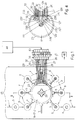
- the machine comprises a vertical turret 1 which, by suitable means, is caused to rotate continuously in the direction indicated for example by the arrow F, and that a disc 2 of any suitable material for the formation of a rotary joint, for example a ceramic material, is fixed to the turret.
- the disc 2 is surrounded by a metal ring 3 integral with the said disc and having a plurality of external and angularly equidistant radial collars 4 which form sockets of a known type, with rapid bayoned fitting, for nozzles 5 directed downwards and used for feeding the portions of product.
- Carousel devices of any suitable known type which are consequently not illustrated, operate in phase and integrally with the turret 1 (see Figure 1) and pick up the empty containers 6 from a supply line 7, place a container under each nozzle, raise the container during the filling stage, lower it at the end of this stage, and then transfer each filled container to an output line 8.
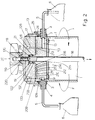
- nozzles 5 are connected to corresponding holes 9-10-11-12-13-14-15-16 formed radially in the disc 2, of varying lengths, and connected through corresponding vertical end holes 109-110-111-112-113-114-115-116 to corresponding concentric annular channels 209-210-211-212-213-214-215-216 formed with precise spacing from each other on the upper face of the disc 2 and having their centres in the axis of this disc.
- a disc 17 of suitable material bears on the disc 2 with a frontal seal and is keyed axially to a shaft 18 connected to means which prevent its rotation, keep it pressed downwards and, when commanded, can raise it through a precise distance (see below).
- the shaft 18 has a tapered upper end part 118, which passes through the stop ring 218, an axial hole in the disc 17, and the central conical part 119 of a cover 19 integral with the said disc.
- the section of shaft 118 is provided with an axial threaded socket into which can be screwed the screw 120 of a knob 20 which, by its conical socket 220, is fitted on the projection 119 of the cover and holds the assembly 17-18-19-20 together.
- the disc 2 has an axial cylindrical projection of round section 102, with an outer seal 21, and this projection is housed rotatably in an axial socket 22 of the fixed disc 17, which is provided with an enlarged upper section 122, so that, when the discs 2 and 17 are in contact with each other as in Figure 2, the said seal 21 does not touch parts of the rotating disc 2.
- the disc 17 has a laterally attached annular body 23 which projects for a precise distance below the said disc, which rotatably surrounds the disc 2 and which is provided with an annular groove with a seal 24 next to the disc 2.
- the disc 2 has an outer annular recess 25 next to the seal 24 which therefore does not bear on rotating parts.
- the cover 19 has, on its perimeter, an integral downward extension 219 which engages with a corresponding slot in the body 23 and which meets the ends of ducts 26-27-28-29-30-31-32-33 which communicate with corresponding horizontal holes 126-127 -128 -129-130-131-132-133 which are provided in the fixed disc 17 and which in turn have their ends connected to corresponding descending holes 226-227-228-229-230-231-232- 233, each of which opens above one of the concentric annular channels 209-210-211-212-213-214-215-216 in the rotating disc 2.
- feeders and the valve means can be disposed in any suitable way, not necessarily in line as shown in Figure 1, but, for example, on a circumference, for driving by means of a barrel cam which is brought into synchronized rotation with the turret 1.
- the metered volume feeders and the corresponding valve means 34-43 are selectively arranged for the suction of the portion of product from the reservoir 44 when a container 6 moves away from a nozzle and the nozzle is moved to interact with a subsequent container, and are arranged for discharge of the portion of product into the container through the rotary joint formed by the discs 2 and 17, when each nozzle passes through that section of the carousel in which the container 6 is raised and engaged by the corresponding nozzle.
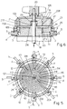
- the vertical holes 226 to 233 which open on the lower face of the fixed disc 17 and connected to the corresponding product feed ducts 26 to 33, communicate with concentric channels 326 to 333 which open on the lower face of the said disc 2 and have the shape of a circular sector and a size such that they cover, for example, approximately 180° of this disc.
- the nozzles 5 are connected to the metered volume feeders and receive from them the portion of product to be introduced into the containers 6.
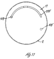
- the holes 109 to 116 which depart from the channels 326 to 333 can interact with closed parts of the lower face of the fixed disc 17 so that they are isolated from the feeders which are switched to the suction stage to form the next portion of product or, as illustrated in the example in Figures 7 and 8, the said holes 109 to 116 may interact with a recess 48 opening on the lower face of the fixed disc 17 and connected at 49 to a suction source which exerts its effect on the nozzles 5 when they are in their inoperative passage, in order to prevent the dripping of product from the nozzles.
- the variant shown in Figures 9 and 10 is based on the preceding variant and demonstrates the possibility of blowing into the containers 6, during the interaction with the product portion feeding carousel, an inert gas and/or one having characteristics promoting the preservation of the packaged product.
- the nozzles 5 have, in addition to the product conveying channel 105, corresponding longitudinal gas supply channels 205, meeting the same number of holes 50 opening on to the upper face of the rotating disc 2, disposed for example on the periphery of this disc and located on an ideal circumference which has its centre in the axis of rotation of the rotary joint.
- the holes 50 In the course of the movement in which the nozzles 5 interact with the containers 6 for the introduction of the portions of product into them, the holes 50, indicated by broken lines in Figure 10, interact in their turn with a channel 51 in the form of a sector of a circle, which also has its centre in the axis of the rotary joint, opens on the lower face of the fixed disc 17, covers, for example, approximately 180° of the disc, and is connected to at least one sanitizing gas delivery duct 52.
Landscapes
- Engineering & Computer Science (AREA)
- Mechanical Engineering (AREA)
- Filling Of Jars Or Cans And Processes For Cleaning And Sealing Jars (AREA)
- Medicines Containing Antibodies Or Antigens For Use As Internal Diagnostic Agents (AREA)
Applications Claiming Priority (2)
| Application Number | Priority Date | Filing Date | Title |
|---|---|---|---|
| ITBO930310A IT1263451B (it) | 1993-07-01 | 1993-07-01 | Macchina automatica, a giostra, per il dosaggio ed il confezionamento di prodotti fluidi, con dosatori disgiunti dalla giostra stessa e facilmente ispezionabili. |
| ITBO930310 | 1993-07-01 |
Publications (2)
| Publication Number | Publication Date |
|---|---|
| EP0631977A1 true EP0631977A1 (fr) | 1995-01-04 |
| EP0631977B1 EP0631977B1 (fr) | 1996-05-22 |
Family
ID=11339167
Family Applications (1)
| Application Number | Title | Priority Date | Filing Date |
|---|---|---|---|
| EP94109779A Expired - Lifetime EP0631977B1 (fr) | 1993-07-01 | 1994-06-24 | Machine automatique en forme de carrousel pour l'approvisionnement et l'emballage de quantités dosées de produits fluides |
Country Status (5)
| Country | Link |
|---|---|
| US (1) | US5551491A (fr) |
| EP (1) | EP0631977B1 (fr) |
| JP (1) | JPH0752997A (fr) |
| DE (1) | DE69400198T2 (fr) |
| IT (1) | IT1263451B (fr) |
Cited By (6)
| Publication number | Priority date | Publication date | Assignee | Title |
|---|---|---|---|---|
| EP0728667A1 (fr) * | 1995-02-21 | 1996-08-28 | Seiko Co., Ltd. | Procédé et dispositif de remplissage de liquides |
| EP0749938A1 (fr) * | 1995-06-21 | 1996-12-27 | Girardin Packaging | Machine pour le conditionnement de produits de parfumerie, de cosmétologie et de pharmacie |
| EP2465813A1 (fr) * | 2010-12-15 | 2012-06-20 | Krones AG | Répartiteur rotatif de fluide |
| ITPR20110033A1 (it) * | 2011-05-02 | 2012-11-03 | Gea Procomac Spa | Distributore rotante di fluido |
| ITTO20120546A1 (it) * | 2012-06-21 | 2013-12-22 | Sidel Spa Con Socio Unico | Unita' di trasferimento per trasferire contenitori destinati a essere riempiti con un prodotto versabile e metodo di iniezione di un fluido inerte all'interno di tali contenitori |
| IT201800003986A1 (it) * | 2018-03-27 | 2019-09-27 | Carlo Francesco Crespi | Nuovo collettore per risciacquatrici e riempitrici industriali, caratterizzato dal fatto di possedere come sua primaria peculiarità, un corpo cilindrico centrale, su cui strisciano le tenute del collettore, interamente costruito in ceramica sinterizzata, o con altri materiali sinterizzati simili |
Families Citing this family (16)
| Publication number | Priority date | Publication date | Assignee | Title |
|---|---|---|---|---|
| US6305437B1 (en) * | 2000-05-31 | 2001-10-23 | Fogg Filler Company | Rotary union assembly for filler device and associated method |
| US6562201B2 (en) * | 2001-06-08 | 2003-05-13 | Applied Semiconductor, Inc. | Semiconductive polymeric system, devices incorporating the same, and its use in controlling corrosion |
| ITMI20021030A1 (it) * | 2002-05-14 | 2003-11-14 | Ronchi Mario Spa | Dispositivo per l'alimentazione in linea di additivi ad un prodotto di base particolarmente per macchine riempitrici e relativa macchina rie |
| JP4396418B2 (ja) * | 2004-06-28 | 2010-01-13 | 澁谷工業株式会社 | 充填装置 |
| FR2899219B1 (fr) * | 2006-03-30 | 2008-06-27 | Sidel Participations | Dispositif pour injecter un fluide dans des recipients en mouvement |
| DE102007041685A1 (de) * | 2007-09-01 | 2009-03-05 | Krones Ag | Vorrichtung zum Verteilen eines Mediums auf Behältnisse |
| DE102009014405A1 (de) | 2009-03-26 | 2010-09-30 | Khs Ag | Transportstern mit Antrieb zum Einbau in Flaschenbehandlungsanlagen |
| JP6517177B2 (ja) * | 2016-09-30 | 2019-05-22 | 大日本印刷株式会社 | 無菌炭酸飲料充填システム及び無菌炭酸飲料充填方法 |
| US10479668B2 (en) | 2016-11-08 | 2019-11-19 | Pepsico, Inc. | Ambient filling system and method |
| DE102018215227A1 (de) * | 2018-09-07 | 2020-03-12 | Krones Ag | Medienverteiler für Rundläufermaschine und Füllmaschine |
| CN109678098B (zh) * | 2018-12-24 | 2020-11-24 | 苏师大半导体材料与设备研究院(邳州)有限公司 | 一种具有清洗收集且便于接料均料操作的圆形分液装置 |
| CN109678099B (zh) * | 2018-12-25 | 2021-06-22 | 鹤壁市人民医院 | 一种生物试剂定量分装装置 |
| CN111942625B (zh) * | 2020-08-29 | 2022-04-08 | 李文泽 | 分装机 |
| CN112340077A (zh) * | 2020-11-15 | 2021-02-09 | 湖南味了谁食品有限责任公司 | 一种带称重组件的全自动灌装机 |
| CN115403102B (zh) * | 2022-08-30 | 2023-04-14 | 中山市美力新电子科技有限公司 | 一种高效的太赫兹水的制备方法及智能装置 |
| DE102023133841A1 (de) * | 2023-12-04 | 2025-06-05 | Arburg Gmbh + Co Kg | Drehdurchführung |
Citations (4)
| Publication number | Priority date | Publication date | Assignee | Title |
|---|---|---|---|---|
| FR657427A (fr) * | 1927-07-15 | 1929-05-22 | Perfectionnements aux machines pour le remplissage en poussières, poudres ou matières analogues, de récipients | |
| DE3024271A1 (de) * | 1979-06-29 | 1981-01-15 | Toulouse Inst Serotherapie | Mechanische vorrichtung zum abfuellen dosierter mengen von fluessigkeiten oder pulvern in behaelter |
| EP0037170A1 (fr) * | 1980-03-05 | 1981-10-07 | Solbern Corp. | Procédé et dispositif pour le remplissage de récipients avec des liquides |
| WO1989008584A1 (fr) * | 1988-03-16 | 1989-09-21 | Ropak Manufacturing Company, Inc. | Appareil d'empaquetage de matieres fluides |
Family Cites Families (6)
| Publication number | Priority date | Publication date | Assignee | Title |
|---|---|---|---|---|
| US1770470A (en) * | 1927-07-15 | 1930-07-15 | Hartmann Carl Wilhelm | Filling machine |
| US2665046A (en) * | 1952-02-02 | 1954-01-05 | Liquid Carbonic Corp | Liquid dispenser |
| US2827208A (en) * | 1952-10-02 | 1958-03-18 | Keller & Romer G M B H | Dispensing apparatus |
| US2805688A (en) * | 1956-02-23 | 1957-09-10 | Climax Products Corp | Filling machines and heads and stems therefor |
| US3419053A (en) * | 1966-05-23 | 1968-12-31 | Tanner Dale | Container-filling machine |
| GB8723559D0 (en) * | 1987-10-07 | 1987-11-11 | Glaxo Group Ltd | Machine |
-
1993
- 1993-07-01 IT ITBO930310A patent/IT1263451B/it active IP Right Grant
-
1994
- 1994-06-22 US US08/264,353 patent/US5551491A/en not_active Expired - Fee Related
- 1994-06-24 DE DE69400198T patent/DE69400198T2/de not_active Expired - Fee Related
- 1994-06-24 EP EP94109779A patent/EP0631977B1/fr not_active Expired - Lifetime
- 1994-06-29 JP JP6168667A patent/JPH0752997A/ja active Pending
Patent Citations (4)
| Publication number | Priority date | Publication date | Assignee | Title |
|---|---|---|---|---|
| FR657427A (fr) * | 1927-07-15 | 1929-05-22 | Perfectionnements aux machines pour le remplissage en poussières, poudres ou matières analogues, de récipients | |
| DE3024271A1 (de) * | 1979-06-29 | 1981-01-15 | Toulouse Inst Serotherapie | Mechanische vorrichtung zum abfuellen dosierter mengen von fluessigkeiten oder pulvern in behaelter |
| EP0037170A1 (fr) * | 1980-03-05 | 1981-10-07 | Solbern Corp. | Procédé et dispositif pour le remplissage de récipients avec des liquides |
| WO1989008584A1 (fr) * | 1988-03-16 | 1989-09-21 | Ropak Manufacturing Company, Inc. | Appareil d'empaquetage de matieres fluides |
Cited By (12)
| Publication number | Priority date | Publication date | Assignee | Title |
|---|---|---|---|---|
| EP0728667A1 (fr) * | 1995-02-21 | 1996-08-28 | Seiko Co., Ltd. | Procédé et dispositif de remplissage de liquides |
| EP0749938A1 (fr) * | 1995-06-21 | 1996-12-27 | Girardin Packaging | Machine pour le conditionnement de produits de parfumerie, de cosmétologie et de pharmacie |
| EP2465813A1 (fr) * | 2010-12-15 | 2012-06-20 | Krones AG | Répartiteur rotatif de fluide |
| CN102537417A (zh) * | 2010-12-15 | 2012-07-04 | 克罗内斯股份公司 | 流体转动分配器 |
| CN102537417B (zh) * | 2010-12-15 | 2016-01-20 | 克罗内斯股份公司 | 流体转动分配器 |
| ITPR20110033A1 (it) * | 2011-05-02 | 2012-11-03 | Gea Procomac Spa | Distributore rotante di fluido |
| WO2012150513A1 (fr) * | 2011-05-02 | 2012-11-08 | Gea Procomac S.P.A. | Distributeur de fluide rotatif |
| CN103269971A (zh) * | 2011-05-02 | 2013-08-28 | Gea普洛克玛柯股份公司 | 转动式流体分配器 |
| CN103269971B (zh) * | 2011-05-02 | 2015-10-07 | Gea普洛克玛柯股份公司 | 转动式流体分配器 |
| ITTO20120546A1 (it) * | 2012-06-21 | 2013-12-22 | Sidel Spa Con Socio Unico | Unita' di trasferimento per trasferire contenitori destinati a essere riempiti con un prodotto versabile e metodo di iniezione di un fluido inerte all'interno di tali contenitori |
| EP2676919A1 (fr) * | 2012-06-21 | 2013-12-25 | Sidel S.p.a. Con Socio Unico | Système de production permettant de produire des contenants devant être remplis d'un produit alimentaire versable et procédé associé |
| IT201800003986A1 (it) * | 2018-03-27 | 2019-09-27 | Carlo Francesco Crespi | Nuovo collettore per risciacquatrici e riempitrici industriali, caratterizzato dal fatto di possedere come sua primaria peculiarità, un corpo cilindrico centrale, su cui strisciano le tenute del collettore, interamente costruito in ceramica sinterizzata, o con altri materiali sinterizzati simili |
Also Published As
| Publication number | Publication date |
|---|---|
| JPH0752997A (ja) | 1995-02-28 |
| DE69400198D1 (de) | 1996-06-27 |
| ITBO930310A1 (it) | 1995-01-01 |
| US5551491A (en) | 1996-09-03 |
| IT1263451B (it) | 1996-08-05 |
| EP0631977B1 (fr) | 1996-05-22 |
| ITBO930310A0 (it) | 1993-07-01 |
| DE69400198T2 (de) | 1996-10-02 |
Similar Documents
| Publication | Publication Date | Title |
|---|---|---|
| EP0631977B1 (fr) | Machine automatique en forme de carrousel pour l'approvisionnement et l'emballage de quantités dosées de produits fluides | |
| US7409971B2 (en) | Machine for dispensing fluid substance into containers | |
| RU2399579C1 (ru) | Обрабатывающая машина | |
| EP0265128B1 (fr) | Remplissage de récipients d'emballage | |
| RU2369556C2 (ru) | Устройство для смены деталей, установленных на вращающихся машинах для обработки емкостей | |
| US5301488A (en) | Programmable filling and capping machine | |
| EP0374586B1 (fr) | Système de lavage et nettoyage sur des machines à emballer | |
| US20120298251A1 (en) | Method and filling element for filling containers with a liquid filling material | |
| US4615165A (en) | Product capsuling plant, particularly for pharmaceutical products | |
| EP3412624B1 (fr) | Machine de remplissage rotative | |
| US7011117B1 (en) | Filling valve | |
| JP3064686B2 (ja) | 製品をポンプ送りする方法およびポンプ装置 | |
| EP0486439B1 (fr) | Dispositif pour l'entraînement synchrone des moyens de remplissage et de manipulation de récipients dans les machines d'embouteillage | |
| US7360345B2 (en) | Beverage bottle cap treatment device | |
| CA1315751C (fr) | Appareil permettant de reduire la production de mousse au remplissage de contenants | |
| CN101045522B (zh) | 用于将流体注入运动容器内的装置 | |
| US4862933A (en) | Doser for sterilizer of a packaging system | |
| US2515871A (en) | Automatic dividing device for conveyer systems | |
| EP0486440A1 (fr) | Dispositif de distribution de produits liquids à des éléments rotatifs, notamment pour machines d'embouteillage | |
| US4298039A (en) | Revolving container processing plant | |
| EP0486438B1 (fr) | Procédé et dispositif pour remplir des récipients avec des produits liquides | |
| JPH03226486A (ja) | 液体物質用ディスペンサー装置 | |
| EP1375412B1 (fr) | Boucheuse pour bouteilles | |
| CN220465845U (zh) | 一种小二碳酸钙d3片生产用自动包装设备 | |
| EP4470965A1 (fr) | Machine de remplissage rotative |
Legal Events
| Date | Code | Title | Description |
|---|---|---|---|
| PUAI | Public reference made under article 153(3) epc to a published international application that has entered the european phase |
Free format text: ORIGINAL CODE: 0009012 |
|
| AK | Designated contracting states |
Kind code of ref document: A1 Designated state(s): DE FR GB IT |
|
| 17P | Request for examination filed |
Effective date: 19950320 |
|
| 17Q | First examination report despatched |
Effective date: 19950530 |
|
| GRAH | Despatch of communication of intention to grant a patent |
Free format text: ORIGINAL CODE: EPIDOS IGRA |
|
| GRAA | (expected) grant |
Free format text: ORIGINAL CODE: 0009210 |
|
| AK | Designated contracting states |
Kind code of ref document: B1 Designated state(s): DE FR GB IT |
|
| REF | Corresponds to: |
Ref document number: 69400198 Country of ref document: DE Date of ref document: 19960627 |
|
| ET | Fr: translation filed | ||
| ITF | It: translation for a ep patent filed | ||
| PLBE | No opposition filed within time limit |
Free format text: ORIGINAL CODE: 0009261 |
|
| STAA | Information on the status of an ep patent application or granted ep patent |
Free format text: STATUS: NO OPPOSITION FILED WITHIN TIME LIMIT |
|
| 26N | No opposition filed | ||
| PGFP | Annual fee paid to national office [announced via postgrant information from national office to epo] |
Ref country code: FR Payment date: 19990430 Year of fee payment: 6 |
|
| PGFP | Annual fee paid to national office [announced via postgrant information from national office to epo] |
Ref country code: DE Payment date: 19990506 Year of fee payment: 6 |
|
| PGFP | Annual fee paid to national office [announced via postgrant information from national office to epo] |
Ref country code: GB Payment date: 19990615 Year of fee payment: 6 |
|
| PG25 | Lapsed in a contracting state [announced via postgrant information from national office to epo] |
Ref country code: GB Free format text: LAPSE BECAUSE OF NON-PAYMENT OF DUE FEES Effective date: 20000624 |
|
| GBPC | Gb: european patent ceased through non-payment of renewal fee |
Effective date: 20000624 |
|
| PG25 | Lapsed in a contracting state [announced via postgrant information from national office to epo] |
Ref country code: FR Free format text: LAPSE BECAUSE OF NON-PAYMENT OF DUE FEES Effective date: 20010228 |
|
| REG | Reference to a national code |
Ref country code: FR Ref legal event code: ST |
|
| PG25 | Lapsed in a contracting state [announced via postgrant information from national office to epo] |
Ref country code: DE Free format text: LAPSE BECAUSE OF NON-PAYMENT OF DUE FEES Effective date: 20010403 |
|
| PG25 | Lapsed in a contracting state [announced via postgrant information from national office to epo] |
Ref country code: IT Free format text: LAPSE BECAUSE OF NON-PAYMENT OF DUE FEES;WARNING: LAPSES OF ITALIAN PATENTS WITH EFFECTIVE DATE BEFORE 2007 MAY HAVE OCCURRED AT ANY TIME BEFORE 2007. THE CORRECT EFFECTIVE DATE MAY BE DIFFERENT FROM THE ONE RECORDED. Effective date: 20050624 |