EP0632966A1 - Vorrichtung und Verfahren zum Abkühlen von Lebensmitteln - Google Patents
Vorrichtung und Verfahren zum Abkühlen von Lebensmitteln Download PDFInfo
- Publication number
- EP0632966A1 EP0632966A1 EP94304302A EP94304302A EP0632966A1 EP 0632966 A1 EP0632966 A1 EP 0632966A1 EP 94304302 A EP94304302 A EP 94304302A EP 94304302 A EP94304302 A EP 94304302A EP 0632966 A1 EP0632966 A1 EP 0632966A1
- Authority
- EP
- European Patent Office
- Prior art keywords
- circular member
- food
- food product
- storage compartment
- product
- Prior art date
- Legal status (The legal status is an assumption and is not a legal conclusion. Google has not performed a legal analysis and makes no representation as to the accuracy of the status listed.)
- Granted
Links
- 235000013305 food Nutrition 0.000 title claims abstract description 132
- 238000000034 method Methods 0.000 title claims abstract description 11
- 238000003860 storage Methods 0.000 claims abstract description 38
- 239000000126 substance Substances 0.000 claims abstract description 23
- 238000009826 distribution Methods 0.000 claims abstract description 18
- 238000005192 partition Methods 0.000 claims abstract description 11
- 239000007788 liquid Substances 0.000 claims description 11
- 238000001816 cooling Methods 0.000 claims description 8
- 239000007787 solid Substances 0.000 claims description 6
- 239000002826 coolant Substances 0.000 claims description 5
- 230000033001 locomotion Effects 0.000 claims description 3
- CURLTUGMZLYLDI-UHFFFAOYSA-N Carbon dioxide Chemical compound O=C=O CURLTUGMZLYLDI-UHFFFAOYSA-N 0.000 description 20
- IJGRMHOSHXDMSA-UHFFFAOYSA-N Atomic nitrogen Chemical compound N#N IJGRMHOSHXDMSA-UHFFFAOYSA-N 0.000 description 12
- 229910002092 carbon dioxide Inorganic materials 0.000 description 9
- 239000001569 carbon dioxide Substances 0.000 description 9
- 229910052757 nitrogen Inorganic materials 0.000 description 6
- 235000013372 meat Nutrition 0.000 description 4
- 244000144977 poultry Species 0.000 description 4
- 239000012267 brine Substances 0.000 description 3
- HPALAKNZSZLMCH-UHFFFAOYSA-M sodium;chloride;hydrate Chemical compound O.[Na+].[Cl-] HPALAKNZSZLMCH-UHFFFAOYSA-M 0.000 description 3
- 235000011089 carbon dioxide Nutrition 0.000 description 2
- 238000004806 packaging method and process Methods 0.000 description 2
- 239000002245 particle Substances 0.000 description 2
- 238000009827 uniform distribution Methods 0.000 description 2
- 241000894006 Bacteria Species 0.000 description 1
- 239000012141 concentrate Substances 0.000 description 1
- 238000007796 conventional method Methods 0.000 description 1
- 230000008878 coupling Effects 0.000 description 1
- 238000010168 coupling process Methods 0.000 description 1
- 238000005859 coupling reaction Methods 0.000 description 1
- 238000005520 cutting process Methods 0.000 description 1
- 230000000694 effects Effects 0.000 description 1
- 239000007789 gas Substances 0.000 description 1
- 238000002347 injection Methods 0.000 description 1
- 239000007924 injection Substances 0.000 description 1
- 238000004519 manufacturing process Methods 0.000 description 1
- 239000008188 pellet Substances 0.000 description 1
- 230000032258 transport Effects 0.000 description 1
- XLYOFNOQVPJJNP-UHFFFAOYSA-N water Substances O XLYOFNOQVPJJNP-UHFFFAOYSA-N 0.000 description 1
Images

Classifications
-
- F—MECHANICAL ENGINEERING; LIGHTING; HEATING; WEAPONS; BLASTING
- F25—REFRIGERATION OR COOLING; COMBINED HEATING AND REFRIGERATION SYSTEMS; HEAT PUMP SYSTEMS; MANUFACTURE OR STORAGE OF ICE; LIQUEFACTION SOLIDIFICATION OF GASES
- F25D—REFRIGERATORS; COLD ROOMS; ICE-BOXES; COOLING OR FREEZING APPARATUS NOT OTHERWISE PROVIDED FOR
- F25D3/00—Devices using other cold materials; Devices using cold-storage bodies
- F25D3/10—Devices using other cold materials; Devices using cold-storage bodies using liquefied gases, e.g. liquid air
-
- A—HUMAN NECESSITIES
- A23—FOODS OR FOODSTUFFS; TREATMENT THEREOF, NOT COVERED BY OTHER CLASSES
- A23B—PRESERVATION OF FOODS, FOODSTUFFS OR NON-ALCOHOLIC BEVERAGES; CHEMICAL RIPENING OF FRUIT OR VEGETABLES
- A23B2/00—Preservation of foods or foodstuffs, in general
- A23B2/80—Freezing; Subsequent thawing; Cooling
- A23B2/85—Freezing; Subsequent thawing; Cooling with addition of or treatment with chemicals
- A23B2/88—Freezing; Subsequent thawing; Cooling with addition of or treatment with chemicals with direct contact between the food and the chemical, e.g. liquid N2 at cryogenic temperature
-
- A—HUMAN NECESSITIES
- A23—FOODS OR FOODSTUFFS; TREATMENT THEREOF, NOT COVERED BY OTHER CLASSES
- A23B—PRESERVATION OF FOODS, FOODSTUFFS OR NON-ALCOHOLIC BEVERAGES; CHEMICAL RIPENING OF FRUIT OR VEGETABLES
- A23B4/00—Preservation of meat, sausages, fish or fish products
- A23B4/06—Freezing; Subsequent thawing; Cooling
- A23B4/08—Freezing; Subsequent thawing; Cooling with addition of chemicals or treatment with chemicals before or during cooling, e.g. in the form of an ice coating or frozen block
- A23B4/09—Freezing; Subsequent thawing; Cooling with addition of chemicals or treatment with chemicals before or during cooling, e.g. in the form of an ice coating or frozen block with direct contact between the food and the chemical, e.g. liquid N2, at cryogenic temperature
Definitions
- the present invention is generally directed to a device for chilling a food product in which the food product is uniformly distributed within a food receiving vessel while simultaneously being uniformly treated with a cryogenic substance to effect cooling.
- the brine treated product is then cut and/or ground as desired prior to packaging.
- the cutting/ grinding step generates heat thereby increasing the temperature of the food product.
- Prior to packaging the food product it is necessary to lower the temperature of the food product in the range of from about 30 to 40°F.
- the present invention is generally directed to an apparatus and process for chilling a food product.
- the apparatus comprises a food distribution means for delivering the food product in a uniform manner to a food storage compartment.
- the food distribution means is operatively engaged at the top of the food storage compartment and serves the function of uniformly distributing the food product within the food storage compartment.
- On the underside of the food distribution means is a cryogen releasing means.
- the cryogen releasing means releases a cryogenic substance onto the food product in a uniform manner as the food product is uniformly distributed within the food storage compartment.
- the food storage compartment receives a uniform distribution of the food product which in turn is uniformly cooled to USDA standards without localized cold spots brought about by uneven coolant distribution.
- the present invention is directed to an apparatus and a process for chilling food products, particular meat and poultry, in an efficient and uniform manner.
- the present device receives the food product from a source such as a conveyer belt and through a unique food distribution means distributes the food product within a food storage compartment in a uniform manner.
- a source such as a conveyer belt
- a unique food distribution means distributes the food product within a food storage compartment in a uniform manner.
- Coupled to the food distribution means in accordance with another aspect of the present invention, is a cryogen releasing means which releases a cryogenic substance in a manner which eliminates cold spots and uniformly cools the food product loaded within the food storage compartment by the food distribution means.
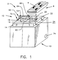
- the apparatus for chilling a food product is shown generally by numeral 2.
- the food product 4 such as cut meat and/or poultry, is delivered to the chilling apparatus 2 by a conventional means such as a conveyor belt 6.
- the apparatus generally includes a storage compartment 10 for receiving the food product 4 and a food distribution device 12 which receives the food product 4 from the conveyor belt 6 and distributes the food product uniformly within the storage compartment 10 as explained hereinafter.
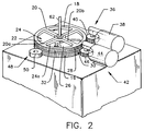
- the food distribution device 12 includes a base 14, a first circular member 16 and a second circular member 18 as shown specifically in Figure 2.
- the second circular member 18 includes at least one, preferably a plurality of spaced-apart partitions 20 (four partitions are shown) which together with the upper surface 22 of the first circular member 16 form a corresponding number of food receiving areas 24.
- the upper surface 22 of the first circular member 16 has an opening 26 therein which is of sufficient size to enable the food product 4 to pass therethrough and into the storage compartment 10.
- the first circular member 16 and the second circular member 18 rotate in a non-congruent manner. That is, for example, the second circular member 18 may either rotate at a different speed than the first circular member 16 and/or rotate in different direction than the first circular member 16.
- the rotation of the respective circular members 16,18 in a non-congruent manner is designed to urge the food product 4 which is received in the food receiving areas 24 into the opening 26 by the partitions 20.
- first circular member 16 and the second circular member 18 The relationship between the first circular member 16 and the second circular member 18 is best shown by reference to Figure 2.
- the partitions 20a and 20b which border the food receiving area 24a rotate in a non-congruent manner such as by rotating at a speed greater than that of the first circular member 16. Accordingly, the food product is caused to move across the upper surface 22 of the first circular member 16 until the food product reaches the opening 26 and falls into the storage compartment 10.
- the same results can be achieved by reversing the rotation of the second circular member 18 with respect to the first circular member 16.
- Rotation of the first and second circular members 16,18 may be accomplished by a gear driving mechanism having respective gear wheels which engage the outer rim of the respective circular members.
- a gear driving mechanism having respective gear wheels which engage the outer rim of the respective circular members.
- the first circular member 16 having an outside edge 28 composed of gear teeth 30.
- the second circular member 18 has a corresponding outside edge 32 composed of similar gear teeth 34.
- the gear teeth 34 of the second circular member 18 are engaged by a first gear drive 36 comprising a motor 38 and a gear wheel 40.
- a first gear drive 36 comprising a motor 38 and a gear wheel 40.
- the rotation of the gear wheel 40 causes the first circular member 16 to rotate in a like manner at a set speed.
- a similar gear drive 42 comprising a motor 44 and corresponding gear wheel 46 is provided for the first circular member 16 which causes the first circular member 16 to rotate at a desired speed.
- the gear wheel 40 causes the second circular member 18 to rotate at a rate of speed different than that of the first circular member 16.
- the gear wheel 40 may be caused to rotate in a direction opposite to that of the corresponding gear wheel 46 which controls movement of the first circular member 16. Accordingly, the food product which enters the food receiving area 24 will be contacted by a partition 20 bordering the food receiving area 24 and pushed along the surface 22 of the first circular member 16. Eventually, the food product 4 will be urged into the opening 26 and deposited within the storage compartment 10.
- Gear drive 40 may be provided with respective ratchet clutches (not shown), known in the art, (e.g. model #400 manufactured by MAYR).
- the ratchet clutch serves to stop the motion of the second circular member 18 when the food product 4 is lodged between one of the partitions 20 and the side of the opening 26 in the upper surface 22 of the first circular member 16.
- This optional device is provided to prevent damage to the apparatus on the rare occasion when the food product 4 may become lodged between the first and the second circular members 16 and 18.
- the food distribution device 12 may also be optionally provided with one or more, preferably three, guide wheels 48 which provide support for the first circular member 16.
- Each guide wheel 48 has an outer rim 50 which rotates and engages the outside edge 28 of the first circular member 16 to assure that the first circular member 16 rotates smoothly when in operation.
- the food distribution system described above effectively transports the food product 4 through the opening 26 at spaced-apart intervals thereby distributing the food product 4 within the storage compartment 10 in a uniform manner. As a consequence, the food product 4 is evenly distributed throughout the entire volume of the storage compartment 10.
- a unique cooling device which relies on a cryogenic substance to cool the food product contained within the food storage compartment.
- a cryogen releasing device is attached to the underside of the first circular member and releases a cryogenic substance as the first circular member is rotated above the storage compartment.
- cryogen releasing device 60 shown affixed to the underside of first circular member 16.
- the cryogen releasing device 60 is shown proximate to the opening 26 in the first circular member 16. It should be noted, however, that the cryogen releasing device 60 may be positioned anywhere along the underside of the first circular member 16.
- the cryogen releasing device 60 includes a first conduit 62 and a second conduit 64 which are connected together by a coupling device 66.
- the second conduit 64 is connected to a source of cryogen (not shown).
- the first conduit 62 which extends upwards through the first and second circular members 16, 18 is connected to at least one device for releasing the cryogenic substance in the desired form for cooling.
- At least one cone-shaped generator 68 is provided for forming solid flakes of carbon dioxide and releasing the flakes of carbon dioxide onto the food product contained within the vessel.
- the solid flakes of carbon dioxide are formed in a conventional manner. More specifically, carbon dioxide is generally shipped and stored in pressure vessels at 300 psig and 0°F, in liquid form. When cooling is needed, it is transferred via a pipe to an orifice. Upon injection through an orifice, the liquid changes state to a solid and gas at atmospheric conditions. The amount of solid formed is approximately 43%.
- the shape of the snow cones or snow generators 68 concentrate the solid carbon dioxide particles forcing them to collide and form larger particles referred to as snow. This snow then contacts the product to be cooled and sublimates giving up its cooling capacity.
- the cryogenic substance is released through the cones 68 as the cryogen releasing device is rotated in accordance with the rotation of the first circular member 16.
- the cryogenic substance may be a liquid, such as liquid nitrogen.
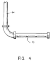
- the first conduit 62 is provided with a series of spaced-apart openings 70 as shown in Figure 4 to allow the liquid nitrogen to drip onto the food product within the storage compartment. Exhaust cryogen is released from the storage vessel through an exhaust port 74 as shown in Figure 1.
- the flow of the cryogenic substance to the cryogen releasing device 60 is controlled by a valve arrangement 72 shown generally in Figure 1.
- the flow of the cryogenic substance may be controlled by adjusting the valve arrangement 70 to limit the amount of cryogenic substance entering the second conduit 64 to a percentage of the total flow capacity. For example, if the conduit 64 is capable of handling 50 pounds per minute of the cryogenic substance (e.g. carbon dioxide or nitrogen) at full production, then the valve 70 could be set at 50% open if only 25 pounds per minute of flow are needed.
- the cryogenic substance e.g. carbon dioxide or nitrogen
- valve arrangement 70 can be turned on and off at spaced-apart intervals. As a result, the valve will be opened a percentage of the time and closed the remaining time. For example, if 50 pounds per minute of the cryogenic substance represented full capacity and only 75% of full capacity were desired, the valve arrangement 70 could be set in the open position for 45 seconds and in the closed position for 15 seconds by a conventional timing device (not shown).
- a storage compartment capable of housing approximately 2200 pounds of meat or poultry is employed for receiving the food product from a conveyor as shown in Figure 1.
- the food product is supplied at a rate sufficient to fill the storage compartment in approximately fifteen minutes.
- the temperature of the food product entering the chilling apparatus is approximately 45°F and the temperature of the food product within the storage compartment is required to be about 35°F.
- the apparatus as shown in Figure 1 is supplied with liquid carbon dioxide which removes heat at the rate of 113 Btu/lb. Since the removal of 70,400 Btu/hr is equivalent to 1173 Btu per minute, approximately 10.4 lbs. of liquid carbon dioxide must be supplied to the storage vessel per minute in order to reduce the temperature of the turkey product from 45°F to 35°F.
- Example 2 The same apparatus as described in Example 1 was employed for cooling turkey except that liquid nitrogen was used as the cryogenic substance with the cryogen releasing device shown in Figure 4. Since liquid nitrogen removes heat at the rate of 85.6 Btu per minute, 13.7 lbs. of liquid nitrogen per minute would be required to reduce the temperature of the turkey product from 45°F to 35 °F.
Landscapes
- Engineering & Computer Science (AREA)
- Chemical & Material Sciences (AREA)
- Life Sciences & Earth Sciences (AREA)
- Polymers & Plastics (AREA)
- Zoology (AREA)
- Food Science & Technology (AREA)
- Wood Science & Technology (AREA)
- Chemical Kinetics & Catalysis (AREA)
- General Chemical & Material Sciences (AREA)
- Combustion & Propulsion (AREA)
- Physics & Mathematics (AREA)
- Mechanical Engineering (AREA)
- Thermal Sciences (AREA)
- General Engineering & Computer Science (AREA)
- Freezing, Cooling And Drying Of Foods (AREA)
Applications Claiming Priority (2)
| Application Number | Priority Date | Filing Date | Title |
|---|---|---|---|
| US08/090,347 US5363658A (en) | 1993-07-09 | 1993-07-09 | Apparatus and process for chilling food products |
| US90347 | 1993-07-09 |
Publications (2)
| Publication Number | Publication Date |
|---|---|
| EP0632966A1 true EP0632966A1 (de) | 1995-01-11 |
| EP0632966B1 EP0632966B1 (de) | 1997-10-29 |
Family
ID=22222399
Family Applications (1)
| Application Number | Title | Priority Date | Filing Date |
|---|---|---|---|
| EP94304302A Expired - Lifetime EP0632966B1 (de) | 1993-07-09 | 1994-06-14 | Vorrichtung und Verfahren zum Abkühlen von Lebensmitteln |
Country Status (6)
| Country | Link |
|---|---|
| US (1) | US5363658A (de) |
| EP (1) | EP0632966B1 (de) |
| CA (1) | CA2123384C (de) |
| DE (1) | DE69406504T2 (de) |
| ID (1) | ID1030B (de) |
| ZA (1) | ZA944209B (de) |
Cited By (3)
| Publication number | Priority date | Publication date | Assignee | Title |
|---|---|---|---|---|
| EP0640295B1 (de) * | 1993-08-30 | 2000-05-03 | The Boc Group, Inc. | Verfahren und Vorrichtung zum Abkühlen von Nahrungsmitteln |
| EP1785352A1 (de) | 2005-11-15 | 2007-05-16 | L'AIR LIQUIDE, Société Anonyme pour l'Etude et l'Exploitation des Procédés Georges Claude | Verfahren und Vorrichtung für das Befüllen eines Behälters mit Lebensmittelartikeln |
| CN113716270A (zh) * | 2021-11-03 | 2021-11-30 | 新三和(烟台)食品有限责任公司 | 冻干食品卸料架 |
Families Citing this family (4)
| Publication number | Priority date | Publication date | Assignee | Title |
|---|---|---|---|---|
| US6178756B1 (en) | 1999-05-14 | 2001-01-30 | Tri-Gas, Inc. | Method and apparatus for chilling perishable liquids |
| ATE427667T1 (de) * | 2005-11-15 | 2009-04-15 | Air Liquide | Verfahren und gerat zur kuhlung von lebensmitteln |
| WO2017127125A1 (en) * | 2016-01-20 | 2017-07-27 | Praxair Technology, Inc. | Method for cryogenically cooling food product |
| CN110713032B (zh) * | 2019-10-22 | 2024-06-04 | 重庆京渝瑞基测控仪器仪表制造有限公司 | 一种旋转式桑叶铺料设备 |
Citations (5)
| Publication number | Priority date | Publication date | Assignee | Title |
|---|---|---|---|---|
| JPS5756231A (en) * | 1980-09-22 | 1982-04-03 | Toyo Kikai Kinzoku Kk | Hopper aparatus for material distribution in form molding machine |
| GB2162328A (en) * | 1984-07-24 | 1986-01-29 | Yamato Scale Co Ltd | Feeding device for combination weighing machine |
| DE3833753A1 (de) * | 1988-03-31 | 1989-08-03 | Edwin Schmidt | Verfahren und vorrichtungen zum tiefkuehlen von kohlendioxidgasfoermig und stickstoff-gasfoermig aus druckbehaeltern, beziehungsweise luft aus druckflaschen oder -erzeugern und deren tiefkalte anwendung |
| EP0422280A1 (de) * | 1989-10-13 | 1991-04-17 | Sauerstoffwerk Friedrich Guttroff Gmbh | Verfahren und Einrichtung zum Kühlen und Gefrieren von wasserhaltigen Lebensmitteln |
| EP0482991A1 (de) * | 1990-10-22 | 1992-04-29 | Institut Francais Du Petrole | Vorrichtung zum Füllen eines Behälters mit rieselfähigem Gut |
Family Cites Families (6)
| Publication number | Priority date | Publication date | Assignee | Title |
|---|---|---|---|---|
| US3368366A (en) * | 1966-02-07 | 1968-02-13 | Wentworth & Ass Inc A F | Machine for glazing frozen foods |
| GB1279076A (en) * | 1970-08-18 | 1972-06-21 | Israel Atomic Energy Comm | Apparatus for the storage of radioactive objects |
| DE2912227C2 (de) * | 1979-03-28 | 1984-07-05 | Dornier System Gmbh, 7990 Friedrichshafen | Dosier- und Entnahmevorrichtung als Verschluss von mit superfluidem Helium gefüllten Behältern |
| JPS60152601U (ja) * | 1984-03-15 | 1985-10-11 | 株式会社 ほくさん | 連続式肝臓片凍結装置 |
| JPS6344857A (ja) * | 1986-08-11 | 1988-02-25 | Nichirei:Kk | 米飯ばら化ドラム装置 |
| FR2641854B1 (fr) * | 1988-12-28 | 1994-01-14 | Carboxyque Francaise | Procede et dispositif de regulation d'un debit de co2 liquide, et application a un tunnel de refroidissement |
-
1993
- 1993-07-09 US US08/090,347 patent/US5363658A/en not_active Expired - Lifetime
-
1994
- 1994-05-11 CA CA002123384A patent/CA2123384C/en not_active Expired - Fee Related
- 1994-05-20 ID IDP940804A patent/ID1030B/id unknown
- 1994-06-14 EP EP94304302A patent/EP0632966B1/de not_active Expired - Lifetime
- 1994-06-14 DE DE69406504T patent/DE69406504T2/de not_active Expired - Fee Related
- 1994-06-14 ZA ZA944209A patent/ZA944209B/xx unknown
Patent Citations (5)
| Publication number | Priority date | Publication date | Assignee | Title |
|---|---|---|---|---|
| JPS5756231A (en) * | 1980-09-22 | 1982-04-03 | Toyo Kikai Kinzoku Kk | Hopper aparatus for material distribution in form molding machine |
| GB2162328A (en) * | 1984-07-24 | 1986-01-29 | Yamato Scale Co Ltd | Feeding device for combination weighing machine |
| DE3833753A1 (de) * | 1988-03-31 | 1989-08-03 | Edwin Schmidt | Verfahren und vorrichtungen zum tiefkuehlen von kohlendioxidgasfoermig und stickstoff-gasfoermig aus druckbehaeltern, beziehungsweise luft aus druckflaschen oder -erzeugern und deren tiefkalte anwendung |
| EP0422280A1 (de) * | 1989-10-13 | 1991-04-17 | Sauerstoffwerk Friedrich Guttroff Gmbh | Verfahren und Einrichtung zum Kühlen und Gefrieren von wasserhaltigen Lebensmitteln |
| EP0482991A1 (de) * | 1990-10-22 | 1992-04-29 | Institut Francais Du Petrole | Vorrichtung zum Füllen eines Behälters mit rieselfähigem Gut |
Non-Patent Citations (1)
| Title |
|---|
| PATENT ABSTRACTS OF JAPAN vol. 6, no. 130 (M - 143)<1008> 16 July 1982 (1982-07-16) * |
Cited By (6)
| Publication number | Priority date | Publication date | Assignee | Title |
|---|---|---|---|---|
| EP0640295B1 (de) * | 1993-08-30 | 2000-05-03 | The Boc Group, Inc. | Verfahren und Vorrichtung zum Abkühlen von Nahrungsmitteln |
| EP1785352A1 (de) | 2005-11-15 | 2007-05-16 | L'AIR LIQUIDE, Société Anonyme pour l'Etude et l'Exploitation des Procédés Georges Claude | Verfahren und Vorrichtung für das Befüllen eines Behälters mit Lebensmittelartikeln |
| WO2007057331A1 (en) * | 2005-11-15 | 2007-05-24 | L'air Liquide Societe Anonyme Pour L'etude Et L'exploitation Des Procedes Georges Claude | Process and apparatus for filling a container with food articles |
| US8003143B2 (en) | 2005-11-15 | 2011-08-23 | L'air Liquide Societe Anonyme Pour L'etude Et L'exploitation Des Procedes Georges Claude | Process and apparatus for filling a container with food articles |
| CN113716270A (zh) * | 2021-11-03 | 2021-11-30 | 新三和(烟台)食品有限责任公司 | 冻干食品卸料架 |
| CN113716270B (zh) * | 2021-11-03 | 2022-02-01 | 新三和(烟台)食品有限责任公司 | 冻干食品卸料架 |
Also Published As
| Publication number | Publication date |
|---|---|
| DE69406504D1 (de) | 1997-12-04 |
| EP0632966B1 (de) | 1997-10-29 |
| US5363658A (en) | 1994-11-15 |
| ID1030B (id) | 1996-10-22 |
| DE69406504T2 (de) | 1998-02-26 |
| CA2123384A1 (en) | 1995-01-10 |
| ZA944209B (en) | 1995-06-13 |
| CA2123384C (en) | 1997-04-08 |
Similar Documents
| Publication | Publication Date | Title |
|---|---|---|
| EP0711511B1 (de) | Apparat und Methode zum Kühlen von weichen Feststoffen und Flüssigkeiten | |
| US5921091A (en) | Liquid air food freezer and method | |
| CA2435214C (en) | Method and apparatus for chilling a food product | |
| US5363658A (en) | Apparatus and process for chilling food products | |
| AU7426387A (en) | Process and apparatus for freezing liquid or semiliquid foods in the form of essentially uniform pellets | |
| US4539824A (en) | Apparatus for continuously freezing liver piece | |
| US3435632A (en) | Conveyor-type freezer using carbon dioxide snow | |
| EP0640295B1 (de) | Verfahren und Vorrichtung zum Abkühlen von Nahrungsmitteln | |
| CA2080202C (en) | Wheel type freezer and method for rapid, low temperature freezing | |
| US5438840A (en) | Field harvest cooling system | |
| US6120828A (en) | Method for freezing boiled rice in separate small-lump form | |
| US4195098A (en) | Method of preparing bacon slabs for slicing | |
| CA2121647A1 (en) | Method and apparatus for producing a frozen crust on a food loaf | |
| US3738121A (en) | Temperature modifying apparatus using expendable refrigerant | |
| US4864923A (en) | Apparatus for cooling pieces of meat | |
| US12520854B2 (en) | System for cooling non-liquid conveyable product | |
| SU660869A1 (ru) | Транспортный рефрижератор дл перевозки скоропорт щихс продуктов | |
| US3232068A (en) | Loading freeze dryers | |
| AU684598B2 (en) | Field harvest cooling system | |
| SU1191699A2 (ru) | Контейнер дл перевозки скоропорт щихс пищевых продуктов | |
| TH17768A (th) | เครื่องสำเร็จและกระบวนการสำหรับการแช่เย็นผลิตภัณฑ์อาหาร | |
| Briley | Variable retention time freezers | |
| TH6916B (th) | เครื่องสำเร็จและกระบวนการสำหรับการแช่เย็นผลิตภัณฑ์อาหาร | |
| WO2000013973A1 (en) | Food container | |
| JPS61249375A (ja) | 食品の処理方法 |
Legal Events
| Date | Code | Title | Description |
|---|---|---|---|
| PUAI | Public reference made under article 153(3) epc to a published international application that has entered the european phase |
Free format text: ORIGINAL CODE: 0009012 |
|
| AK | Designated contracting states |
Kind code of ref document: A1 Designated state(s): BE DE FR GB IT NL SE |
|
| 17P | Request for examination filed |
Effective date: 19950531 |
|
| 17Q | First examination report despatched |
Effective date: 19951207 |
|
| GRAG | Despatch of communication of intention to grant |
Free format text: ORIGINAL CODE: EPIDOS AGRA |
|
| GRAH | Despatch of communication of intention to grant a patent |
Free format text: ORIGINAL CODE: EPIDOS IGRA |
|
| GRAH | Despatch of communication of intention to grant a patent |
Free format text: ORIGINAL CODE: EPIDOS IGRA |
|
| GRAA | (expected) grant |
Free format text: ORIGINAL CODE: 0009210 |
|
| ITF | It: translation for a ep patent filed | ||
| AK | Designated contracting states |
Kind code of ref document: B1 Designated state(s): BE DE FR GB IT NL SE |
|
| ET | Fr: translation filed | ||
| REF | Corresponds to: |
Ref document number: 69406504 Country of ref document: DE Date of ref document: 19971204 |
|
| PLBE | No opposition filed within time limit |
Free format text: ORIGINAL CODE: 0009261 |
|
| STAA | Information on the status of an ep patent application or granted ep patent |
Free format text: STATUS: NO OPPOSITION FILED WITHIN TIME LIMIT |
|
| 26N | No opposition filed | ||
| REG | Reference to a national code |
Ref country code: GB Ref legal event code: IF02 |
|
| PGFP | Annual fee paid to national office [announced via postgrant information from national office to epo] |
Ref country code: IT Payment date: 20070628 Year of fee payment: 14 |
|
| PGFP | Annual fee paid to national office [announced via postgrant information from national office to epo] |
Ref country code: DE Payment date: 20080731 Year of fee payment: 15 Ref country code: NL Payment date: 20080624 Year of fee payment: 15 |
|
| PGFP | Annual fee paid to national office [announced via postgrant information from national office to epo] |
Ref country code: FR Payment date: 20080617 Year of fee payment: 15 |
|
| PGFP | Annual fee paid to national office [announced via postgrant information from national office to epo] |
Ref country code: GB Payment date: 20080627 Year of fee payment: 15 |
|
| PGFP | Annual fee paid to national office [announced via postgrant information from national office to epo] |
Ref country code: SE Payment date: 20080627 Year of fee payment: 15 Ref country code: BE Payment date: 20080730 Year of fee payment: 15 |
|
| PG25 | Lapsed in a contracting state [announced via postgrant information from national office to epo] |
Ref country code: IT Free format text: LAPSE BECAUSE OF NON-PAYMENT OF DUE FEES Effective date: 20080614 |
|
| BERE | Be: lapsed |
Owner name: THE *BOC GROUP INC. Effective date: 20090630 |
|
| GBPC | Gb: european patent ceased through non-payment of renewal fee |
Effective date: 20090614 |
|
| NLV4 | Nl: lapsed or anulled due to non-payment of the annual fee |
Effective date: 20100101 |
|
| REG | Reference to a national code |
Ref country code: FR Ref legal event code: ST Effective date: 20100226 |
|
| PG25 | Lapsed in a contracting state [announced via postgrant information from national office to epo] |
Ref country code: FR Free format text: LAPSE BECAUSE OF NON-PAYMENT OF DUE FEES Effective date: 20090630 |
|
| PG25 | Lapsed in a contracting state [announced via postgrant information from national office to epo] |
Ref country code: GB Free format text: LAPSE BECAUSE OF NON-PAYMENT OF DUE FEES Effective date: 20090614 |
|
| PG25 | Lapsed in a contracting state [announced via postgrant information from national office to epo] |
Ref country code: DE Free format text: LAPSE BECAUSE OF NON-PAYMENT OF DUE FEES Effective date: 20100101 Ref country code: BE Free format text: LAPSE BECAUSE OF NON-PAYMENT OF DUE FEES Effective date: 20090630 |
|
| PG25 | Lapsed in a contracting state [announced via postgrant information from national office to epo] |
Ref country code: NL Free format text: LAPSE BECAUSE OF NON-PAYMENT OF DUE FEES Effective date: 20100101 |
|
| PG25 | Lapsed in a contracting state [announced via postgrant information from national office to epo] |
Ref country code: SE Free format text: LAPSE BECAUSE OF NON-PAYMENT OF DUE FEES Effective date: 20090615 |