EP0633464A2 - Détecteur de particules - Google Patents
Détecteur de particules Download PDFInfo
- Publication number
- EP0633464A2 EP0633464A2 EP94304865A EP94304865A EP0633464A2 EP 0633464 A2 EP0633464 A2 EP 0633464A2 EP 94304865 A EP94304865 A EP 94304865A EP 94304865 A EP94304865 A EP 94304865A EP 0633464 A2 EP0633464 A2 EP 0633464A2
- Authority
- EP
- European Patent Office
- Prior art keywords
- slit
- detector
- particle monitoring
- window
- optical
- Prior art date
- Legal status (The legal status is an assumption and is not a legal conclusion. Google has not performed a legal analysis and makes no representation as to the accuracy of the status listed.)
- Withdrawn
Links
Images


Classifications
-
- G—PHYSICS
- G01—MEASURING; TESTING
- G01N—INVESTIGATING OR ANALYSING MATERIALS BY DETERMINING THEIR CHEMICAL OR PHYSICAL PROPERTIES
- G01N21/00—Investigating or analysing materials by the use of optical means, i.e. using sub-millimetre waves, infrared, visible or ultraviolet light
- G01N21/01—Arrangements or apparatus for facilitating the optical investigation
- G01N21/15—Preventing contamination of the components of the optical system or obstruction of the light path
-
- G—PHYSICS
- G01—MEASURING; TESTING
- G01N—INVESTIGATING OR ANALYSING MATERIALS BY DETERMINING THEIR CHEMICAL OR PHYSICAL PROPERTIES
- G01N21/00—Investigating or analysing materials by the use of optical means, i.e. using sub-millimetre waves, infrared, visible or ultraviolet light
- G01N21/17—Systems in which incident light is modified in accordance with the properties of the material investigated
- G01N21/47—Scattering, i.e. diffuse reflection
- G01N21/49—Scattering, i.e. diffuse reflection within a body or fluid
- G01N21/53—Scattering, i.e. diffuse reflection within a body or fluid within a flowing fluid, e.g. smoke
Definitions
- This invention relates to a particle monitoring system and to a method of detecting particulate material.
- particle monitors are laser-based optical systems designed to detect the low levels of scattered light produced when the laser light interacts with the particulate matter in the exhaust line flow. Sustained operation of such particle monitoring sensors is made difficult by the harsh chemical environment that exists in the exhaust line flow of semiconductor processing equipment. Chemical species within the exhaust gases deposit on the walls of the exhaust lines, and these species may deposit on or etch surfaces that are not suitably inert to the exhaust gas environment. Optical surfaces which face the interior of the exhaust line, such as those necessary for a low light level optical detection system, are quickly degraded in such an environment.
- Increased scattering in the particle monitoring sensor's optical path may significantly diminish the signal to noise ratio for the sensor and thereby render it ineffective.
- particulate matter deposited on the detector windows can reduce the level of light gathered by the collection optics, reducing the total signal level.
- a poor optical surface on the laser inlet window can scatter the input laser beam and the scattered beam may enter the detector, introducing an optical noise signal into the particle monitoring sensor. This noise signal can be so strong that no particle detection would be possible.
- the reactor must be taken out of service frequently to service the particle monitoring sensor by cleaning or replacing the optical surfaces. Because existing particle monitoring sensors are often integral parts of the reactor exhaust system, such servicing renders the host equipment inoperable and reduces the practicality of particle monitoring sensors.
- Another technique described in the '865 patent limits the degradation of optical surfaces by heating the optical surfaces to suppress deposition from the exhaust gases onto the surfaces of the particle monitoring system optical surfaces.
- a large heater is attached to the exhaust line upstream from the particle detection system. Heat is input to the exhaust line to heat the surfaces of the windows of that particle monitoring system. In practice, less heat than is input actually reaches the windows, probably because of the relatively low thermal conductivity of the stainless steel exhaust line. For high heating levels, an undesirable amount of heat may propagate through other parts of the particle monitoring system. This heat increases the operating temperature of both the semiconductor photodetector and the semiconductor laser diode, diminishing the performance and reducing the lifetime of both elements.
- a particle monitoring sensor comprises a chamber through which particulate matter flows.
- a coherent light source directs light into the chamber, where the light interacts with the particulate matter to produce a scattered light signal.
- a portion of the scattered light passes through a collection optical element to an optical detector.
- a heating element is disposed in thermal contact with the collection optical element but is in poor thermal contact with the optical detector. In this way, the heating element maintains the collection optical element at an elevated temperature.
- a particle monitoring sensor comprises a linearly polarized laser which emits light toward a scattering region.
- the particle monitoring sensor also includes a detector and collection optics, wherein the detector, the collection optics and at least a portion of the scattering region lie along an optical path.
- a slit is disposed along the optical path. The elongated axis of the slit is disposed substantially perpendicular to the polarization direction of the laser light.
- a stream of substantially nonreactive gas is directed over at least some of the optical surfaces within a Particle monitoring sensor.
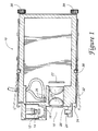
- Fig. 1 shows a cross-sectional view of a particle monitoring sensor in accordance with the present invention.
- Fig. 2 shows a side view of a particle monitoring sensor of the present invention.
- Fig. 3 shows an enlarged cross-sectional view of a portion of a particle monitoring sensor of the present invention.
- Fig. 4 is a schematic illustration of a slit assembly in accordance with an aspect of the present invention.
- the present invention is directed to a particle monitoring sensor.
- the optical surfaces of a particle monitoring sensor are protected from optical deterioration using one or more of the aspects of the present invention.
- Such optical surfaces might be the surfaces of windows which face on the processing environment within a piece of semiconductor processing equipment.
- One aspect of the present invention may utilize a field of view limiting slit to reduce the amount of optical surface area exposed to the processing environment.
- this embodiment of the present invention is used in conjunction with a coherent polarized light source disposed so that the scattered optical signal quality is only slightly reduced from the levels observed without the field of view limiting slit.
- Another aspect of the present invention incorporates a heater in thermal contact with one or more of the optical surfaces of the particle monitoring sensor.
- the heater is in much better thermal contact with the optical surface than with either the light source or the detector of the particle monitoring sensor.
- a stream of substantially inert gas is directed across the optical surfaces of the particle monitoring sensor that face on the processing environment.
- Preferred embodiments of the present invention are used in conjunction with semiconductor processing equipment such as the chemical vapor deposition reactor described in U.S. Patent No. 4,872,947, which is entitled “CVD of Silicon Oxide Using TEOS Decomposition and In-Situ Planarization Process.”
- Certain embodiments of the present invention may be used for process monitoring in semiconductor equipment.
- One such application is described in U.S. Patent No. 5,083,865 entitled “Particle Monitor System and Method," the disclosure of which is hereby incorporated by reference.
- teachings of the present invention may be applied to any particle monitoring sensor which operates at least partially in a harsh environment.
- FIG. 1 shows a particle monitoring sensor in cross section.
- the particle monitoring sensor indicated generally at 10, includes one or more optical surfaces which face on the processing environment of the semiconductor processing equipment.
- optical surfaces may be present on the windows 16, through which light passes in the illustrated embodiment of a particle monitoring sensor.
- the light source optics 14 and collection optics 20 are separated from the harsh chemical environment within the exhaust line by windows 16.
- the windows 16 should be hard, easily cleaned and highly transmissive at the wavelengths emitted by the light source.
- quartz windows may be suitable in some applications, and magnesium fluoride or aluminum oxide may be suitable in others.
- the present invention may utilize any of a number of techniques to limit the operational degradation of the optical surfaces of the windows 16.
- a substantially non-reactive purge gas flows through gas lines to controlled flow connectors 26 and over the surface of the windows 16.
- a thin film heater indicated generally at 28, may be used to heat the surface of the windows 16.
- field of view limiting slits (not shown in Figure 1) may be incorporated to reduce the portion of the windows 16 that are exposed to the harsh chemical environment of the exhaust line.
- the signal to noise ratio of preferred embodiments of the present invention is not unacceptably diminished by using a slit.
- the particle monitoring sensor 10 includes a light source 12 which may be, for example, a 50 mW semiconductor laser operating at about 780 nm.
- Light output by light source 12 is collimated and shaped by optical elements 14.
- the optical elements 14 may include a cylindrical lens and an aspheric lens of the sort typically used for collimating the output beam of semiconductor diode lasers.
- the light from light source 12 passes through the wall of the exhaust line to form an input optical beam.
- the input optical beam enters the chamber defined by the wall of the exhaust line. While in this chamber, the input optical beam may be scattered by interacting with particulate matter or gases within the exhaust flow.
- the region of interaction is indicated generally at 18 in Figure 1.
- the collection optics 20 comprise a pair of aspheric lenses that image the scattering region onto the detector 22.
- each lens may be held in place by a number of small mounting fingers disposed at the edge of each lens. These mounting fingers can be arranged so that it is unlikely that any scattered light will be incident on the mounting fingers.
- Many different types of photodetectors are suitable for use with the present invention. For example, the commercially available photodiode S2551-01 manufactured by Hamamatsu may be used.
- the output of the photodiode may be collected by any of the well known means for data collection and may be translated into a form that is compatible with standard data manipulation techniques.
- the beam produced by the laser diode 12 is preferably shaped into an elongated beam with the breadth of the beam being substantially perpendicular to the flow direction of the gas.
- the junction of the laser diode will preferably be substantially aligned with the flow direction of the exhaust gases. Because the laser beam diverges most rapidly in the direction perpendicular to the diode junction, this alignment will also broaden the beam width in the scattering region. In this geometry, a greater proportion of the cross section of the exhaust line is illuminated. Accordingly, more scattering interactions between the input optical beam and the exhaust gas particulates should occur, and more of the particulate matter flowing in the exhaust line should be detected. Use of this increased scattering geometry is preferably accompanied by using a long, narrow detector. Such a detection geometry allows a greater cross sectional area of the exhaust line to be imaged onto the detector.
- a light trap is incorporated in preferred embodiments of the present invention, even for the 90° observation geometry shown in Figure 1. This is because the use of a light trap reduces the amount of the input optical beam that is reflected within the chamber defined by the exhaust line wall. If the relatively intense input optical beam is allowed to reflect off of the exhaust line wall, the reflected light may create an unwanted background light signal that may be collected by the detector.
- a light trap will, in general, be useful for any collection geometry and, in particular, some form of light trap is desirable when the scattered light is being collected in the forward scattering direction.
- the light trap shown at 24 may be formed, for example, from delrin. Delrin is acceptable because it is readily machinable and because its inner surface can be made to be relatively nonreflecting and relatively absorptive.
- the back surface of the light trap is preferably canted, that is, the back surface is formed at an angle so that it is not perpendicular to the propagation direction of the input optical beam. This canted back surface causes the light that is reflected from the back surface to be directed to the sidewalls of the light trap so that the light not initially absorbed undergoes a number of additional reflections.
- the particle monitoring sensor is shown in side view.
- the particle monitoring sensor is coupled to a section of exhaust line, indicated generally at 40 in that figure.
- vacuum flanges 38 are provided for mounting the section of the exhaust line into the exhaust line vacuum system.
- KF flanges ranging from about one inch up to four or more inches in diameter may be used in the section of exhaust line 40.
- the illustrated section of exhaust line has been modified to include a substantially rectangular opening with a flat surface, indicated generally at 42.
- a flat surface on the particle monitoring sensor (shown at 50 in Figure 3) is mated to the flat surface 42 surrounding the rectangular opening in the modified exhaust line 40.
- a seal of the O-ring type is used to obtain a vacuum junction between the exhaust line and particle monitoring sensor.
- a particle monitoring sensor of the present invention is, in preferred embodiments, a compact unit that is field serviceable.
- a field serviceable particle monitoring sensor should be removable without causing a prolonged shut down of the host processing reactor. It is desirable that the particle monitor be designed ergonomically for ease of removal and so that the same configuration of particle monitoring sensor can be used in a variety of operating environments.
- One aspect of the field serviceability of the described particle monitoring sensor is a simplified mounting system.
- the particle monitoring sensor By turning knobs 30 in one direction, the particle monitoring sensor is securely attached to the modified exhaust line 40 and the O-ring is compressed to form a vacuum seal.
- the particle monitoring sensor By turning the knobs 30 in the opposite direction, and by removing detachable gas lines and electrical connections, the particle monitoring sensor can be removed from the exhaust line for servicing.
- Each of the knobs 30 is coupled to a strap 32 which is slidably mounted along the side of the illustrated particle monitoring sensor. Turning the knob 30 associated with strap 32 causes the strap 32 to slide toward the particle monitoring sensor and causes the hook 34 on the end of the strap to engage a slot on the side of the wall of the exhaust line 40.
- the strap 32 may be a durable metal such as stainless steel.
- a preferred embodiment of the strap system incorporates a slot in the strap 32 which slides over the surface of nylon ball 36.
- the slot 35 is disposed about the nylon ball 36 so that the strap is disposed near the side of the particle monitoring sensor.
- the slot 35 in the strap moves over the surface of the nylon ball until the slot 35 is no longer disposed about the nylon ball 36.
- the strap 32 then rides up and onto the surface of the nylon ball 36 and the strap moves away from the side of the particle monitoring sensor.
- a plate to seal the opening in the exhaust line 40 when the particle monitoring sensor has been removed for servicing.
- a plate might conveniently be mounted on the particle monitoring sensor when it is not needed, such as is shown at 44 in Figure 2.
- Purge gas flows across the optical windows within the particle monitoring device, including the window 56 between the laser and the chamber and the window 54 between the detector and the chamber.
- Suitable gases for purging will be substantially inert and readily available in the semiconductor processing environment.
- nitrogen gas (N2) is used in the illustrated embodiment of a particle monitoring sensor.
- Purge gas enters the particle monitoring sensor through a detachable mechanical fitting coupled to the barbed inlet 52.
- the gas flows through fitting 52 and through connecting hoses (shown in Figure 1, but not in Figure 3) to one or more barbed inlets 26.
- Some of the purge gas flows over the laser window 56 and some flows over the detector window 54.
- the barbs are filled with sintered metal plugs (a standard commercial product) to control the flow rates into each of the two gas channels formed in the structures on which the windows are mounted. In such plugs, the sintering conditions can be varied to produce plugs of increasing density which are correspondingly more restrictive to gas flow.
- the flow rate to the smaller (laser) window is approximately 10 cc/min and the flow rate to the larger ( ⁇ 25 mm diameter) window is approximately 20 cc/min.
- the respective gas channels direct the purge gas to each of the windows. Ports at the end of the gas channels are arranged around the windows so that the purge gas flows radially inward across the windows.
- a plenum is preferably disposed at the periphery of the larger window to distribute the gas uniformly around the exterior of the window.
- a slit assembly 58 is disposed in front of the detector window so that a plate 60, preferably of plastic, but which may also be of metal or other suitable material, partially encloses a space between the plate and the detector window.
- a plate 60 preferably of plastic, but which may also be of metal or other suitable material
- Light passes through a substantially rectangular slit 62 disposed in plate 60 before it passes through the detector window.
- Purge gas enters the space between the plate and the window through a slit port 64 (shown as a dashed line) and passes along a slit gas channel 66 which is connected to slit gas channel (plenum) 68.
- plenum 68 Gas flows through the channel defined by plenum 68 and then radially inward, flowing over the surface of the detector window.
- other plenums could be used which direct gas flows over the surface of a window without using a plastic or metal plate.
- the gas flow need not be radial and might be, for example, linear.
- the velocity at which purge gas flows over the windows may be increased by placing a slit assembly, such as the one shown at 58 in Figures 3 and 4, in front of the surface of the windows. Gas flowing from behind the slit assembly would be forced through a slit 62, which would have the effect of throttling the gas flow, increasing the velocity of the flowing gas without increasing the total flow volume.
- a slit assembly 58 may be placed in front of the detector window 54, increasing the flow velocity over the exposed surface of the window.
- the slit 58 reduces the field of view of the detector 22, reducing the proportion of the scattered light that is collected. Accordingly, there will be an empirical trade off between the flow velocity over the window and the field of view of the detector.
- the signal lost by reducing the slit size may be relatively small in comparison to the greater flow velocity that can be achieved in accordance with the present invention.
- the quality of the purge -- that is, the amount of purge gas that flows by the windows -- is limited by the vacuum environment of the reactor. It is preferable to have a large volume of gas flowing over the optical surfaces exposed to the exhaust line environment. A large gas flow limits the proportion of chemically reactive species that will diffuse to the optical surfaces of the particle monitoring sensor. However, too much purging gas flow into the exhaust line will impair the operation of the reactor. The smaller slit allows the total purging flow rate to be reduced, while maintaining a sufficient flow so as to limit damage to the windows.
- the particle monitoring sensor described in U.S. Patent No. 5,083,865 heats the optical surfaces of the particle monitoring sensor by heating the exhaust line above the particle monitoring sensor.
- This design has certain drawbacks when used to substantially heat the optical surfaces.
- the heat transfer is inefficient. This is because there are a number of interfaces for the heat to-cross to reach the windows.
- the primary pathway for thermal conductance is along the stainless steel exhaust line. Stainless steel is one of the poorest thermal conductors of the metals. Thus, it would be preferable to improve the thermal contact between the heater and the optical surfaces of the particle monitoring sensor.
- heat is applied locally to the windows of the particle monitoring sensor. This allows the windows to be more effectively heated without affecting either the detector or the laser diode.
- a flexible resistive heater 28 is clamped in close proximity to both the window 56 associated with the laser diode and the window 54 associated with the detector.
- a generally circular heating element is disposed at the periphery of each of the windows so that the heater comprises two distinct heating elements. The two heating elements are connected in series and may be driven with a single power source. The glass of each of these windows presses the heater against an O-ring and a spacer so that the heater is in close physical and thermal contact with the window.
- the heater 28 itself is a thin, resistive film of metal sandwiched between two insulating Kapton films, so that the entire heater is about 0.007" thick and is easily flexible.
- Such heaters are well known in the art and are commercially available.
- a 24 Ohm, 3.34 Watt, two-element heater is driven at 9 Volts to heat both of the windows in the particle monitoring sensor.
- Insulating materials with good high temperature stability other than Kapton could, of course, be used in the described heaters.
- the heater need not be flexible, though it is preferred that the heater closely conform to the heated surfaces.
- a heater of this design it should be possible to heat the windows to temperatures approaching or even above 100°C, without substantially harming either the detector or the laser diode. Such temperatures are believed to be desirable for protecting the particle monitoring sensor's windows during, for example, tungsten etch processes.
- Heating of the laser diode 12 is minimized because the diode is thermally isolated from the laser window 56 by a plastic fitting and by a stainless steel or plastic housing.
- the diode is heat-sinked to an aluminum block, so the amount of heat flowing to the diode is relatively small.
- the detector 22 is similarly thermally isolated from the windows in the wall of the chamber.
- the heater 28 is not a separate element but instead comprises a thin metal film directly deposited on the surface of the window.
- the resistive metal film would be disposed away from the center of the window so that the heater does not block light.
- the thin film coating for use as a resistive heater is 80% to 90% transparent, and is applied over the open aperture of the window, or over the entire window including the open aperture. Such coatings are readily commercially available. Contacts are made in any of the well known fashions and the heater is driven in the same manner as is the heater discussed above.
- light incident on particulate matter within the-exhaust gas flow is partially absorbed and reradiated by the particulate matter within the exhaust gas flow.
- the particulate matter appears to absorb and radiate light in a fashion similar to that of a dipole oscillator.
- the optical radiation characteristics of a dipole oscillator are described in Hecht & Zajac, Optics 52-57, 242-45 (1979), which discussion is incorporated herein by reference.
- the scattered optical power is expected to be distributed about the plane normal to the polarization direction, with the maximum of the optical power distribution lying substantially in that plane.
- a linearly polarized semiconductor diode laser is used as an input light source for the particle monitoring sensor.
- the polarization vector of the light produced by the laser is aligned so that it is substantially aligned parallel to the direction of particulate flow in the exhaust line of the reactor.
- light incident on the particulate matter is expected to be scattered primarily into a plane lying substantially perpendicular to the direction of the polarization of the light produced by the laser.
- the linear path of the light produced by the laser preferably lies in substantially in that same plane.
- a slit in the path of the collection optics 20.
- This slit is preferably elongated and may be, for example, a slightly rounded, rectangular opening.
- the direction of elongation is disposed so that the elongation axis is substantially perpendicular to the direction of the polarization of the light input to the particle monitoring sensor.
- the slit is preferably elongated to correspond to the elongated detector 22 used in preferred embodiments of the present invention. The exact size of the opening will depend on where the slit is placed in the optical path and on the particular geometry of the particle monitoring sensor.
- the preferred shape and dimension of the slit is preferably determined empirically by varying the slit size and geometry to optimize the detection area in an operating particle monitoring sensor. Other detection characteristics might also be used to optimize the slit. For example, the particle size detection limit or the total scattered signal might be maximized in evaluating different slits.
- Preferred embodiments of the present invention use an opaque plate, such as slit assembly 58, disposed on the outside of the window 54.
- a stainless steel or a plastic plate 60 with a rounded rectangular opening 62 may be placed to the exhaust line side of a round window in the wall of the exhaust line.
- Suitable plastic materials for this slit might be polyetheretherketone or the "VESPEL" material produced by the Dupont Corporation. This slit covers the round window with the exception of the rectangular opening in the slit.
- the collection window 54 and collection optics 20 may be sectioned so that the portions of the optics not normally involved in refracting scattered light are removed. This allows the total detector assembly to be made thinner.
- the present invention utilizes a 90° scattering geometry as illustrated in the figures.
- the collection optics are disposed so that their principal optical axis is disposed substantially perpendicular to the propagation direction of the incident light.
- the component of light scattered into the 90° direction is much smaller than the component scattered into the forward direction for particles that are relatively large compared to the wavelength of the illuminating light.
- improved signal-to-noise ratios have been observed in accordance with the present invention when employing a 90° collection geometry.
- the scattered light intensity diminishes as the collection angle deviates from the normal to the polarization plane of the incident light.
- the elongated slit used in accordance with certain aspects of the present invention will eliminate some scattering signal, but not an unacceptable amount.
- the smaller slit (4 mm x ⁇ 17 mm) reduces the detection cross section by only about 20% compared to the circular ( ⁇ 17 mm diameter) aperture. That is, when observing the flow of 0.5 ⁇ m particles, the count rate for the elongated slit is about 80% of that observed for the circular aperture.
- This reduction is relatively small when considering the reduction in collection surface area when only a 4 mm x 17 mm slit remains open from a window that is approximately 25 mm in diameter. Because there is little drop off in detection area, the smaller slit is preferred because of its ability to greatly improve the flow velocity over the window 54, thereby slowing the optical degradation of the collection optics window.
- the present invention may also be practiced in a forward scattering geometry.
- the main (unscattered) beam must be eliminated from the forward signal.
- the scattered light signal it is preferable for the scattered light signal to be measured in the dark field.
- the small slit arrangement described herein may also be used in the forward scattering collection geometry.
- a smaller surface area of the collection window will be heated in preferred embodiments of the present invention. Accordingly, less power would need to be input to heat the surface of the window to the same or higher temperature.
Landscapes
- Physics & Mathematics (AREA)
- Health & Medical Sciences (AREA)
- Life Sciences & Earth Sciences (AREA)
- Chemical & Material Sciences (AREA)
- Analytical Chemistry (AREA)
- Biochemistry (AREA)
- General Health & Medical Sciences (AREA)
- General Physics & Mathematics (AREA)
- Immunology (AREA)
- Pathology (AREA)
- Investigating Or Analysing Materials By Optical Means (AREA)
- Optical Measuring Cells (AREA)
Applications Claiming Priority (2)
| Application Number | Priority Date | Filing Date | Title |
|---|---|---|---|
| US88975 | 1993-07-08 | ||
| US08/088,975 US5463460A (en) | 1993-07-08 | 1993-07-08 | Particle monitoring sensor |
Publications (2)
| Publication Number | Publication Date |
|---|---|
| EP0633464A2 true EP0633464A2 (fr) | 1995-01-11 |
| EP0633464A3 EP0633464A3 (fr) | 1996-11-06 |
Family
ID=22214610
Family Applications (1)
| Application Number | Title | Priority Date | Filing Date |
|---|---|---|---|
| EP94304865A Withdrawn EP0633464A3 (fr) | 1993-07-08 | 1994-07-01 | Détecteur de particules. |
Country Status (4)
| Country | Link |
|---|---|
| US (3) | US5463460A (fr) |
| EP (1) | EP0633464A3 (fr) |
| JP (1) | JPH0755687A (fr) |
| KR (1) | KR100340818B1 (fr) |
Cited By (3)
| Publication number | Priority date | Publication date | Assignee | Title |
|---|---|---|---|---|
| AT2224U1 (de) * | 1997-07-28 | 1998-06-25 | Avl List Gmbh | Anordnung zur trübungsmessung |
| GB2396023A (en) * | 2002-10-05 | 2004-06-09 | Oxford Lasers Ltd | Imaging system with purging device to prevent adhesion of particles |
| EP2487480A1 (fr) * | 2011-02-09 | 2012-08-15 | ABB Technology AG | Élément de capteur optique et appareil d'analyse d'échantillons optiques |
Families Citing this family (24)
| Publication number | Priority date | Publication date | Assignee | Title |
|---|---|---|---|---|
| US5463460A (en) * | 1993-07-08 | 1995-10-31 | Applied Materials, Inc. | Particle monitoring sensor |
| JPH08247939A (ja) * | 1995-03-15 | 1996-09-27 | Anritsu Corp | ガス濃度測定装置 |
| US5949537A (en) * | 1996-04-18 | 1999-09-07 | American Air Liquide Inc. | In-line cell for absorption spectroscopy |
| US6084668A (en) * | 1997-07-10 | 2000-07-04 | American Air Liquide Inc. | In-line cell for absorption spectroscopy |
| JPH11183366A (ja) * | 1997-12-25 | 1999-07-09 | Nippon Sanso Kk | 分光分析用測定セル |
| US6078635A (en) * | 1998-02-05 | 2000-06-20 | Dubois; Jerry | Seed or particle-counting device |
| US6421127B1 (en) * | 1999-07-19 | 2002-07-16 | American Air Liquide, Inc. | Method and system for preventing deposition on an optical component in a spectroscopic sensor |
| US6414754B1 (en) * | 2000-03-08 | 2002-07-02 | Pacific Scientific Instruments Company | Method and apparatus for suppressing stray light in particle detectors |
| US6696362B2 (en) | 2001-02-08 | 2004-02-24 | Applied Materials Inc. | Method for using an in situ particle sensor for monitoring particle performance in plasma deposition processes |
| US7301125B2 (en) * | 2001-05-31 | 2007-11-27 | Ric Investments, Llc | Heater for optical gas sensor |
| EP1395177B1 (fr) | 2001-05-31 | 2006-07-19 | Respironics Inc. | Element chauffant pour capteurs de gaz optiques |
| EP1432972A1 (fr) * | 2001-09-07 | 2004-06-30 | Inficon, Inc. | Procede de traitement du signal destine a la surveillance, in situ, des particules par un faisceau d'exploration |
| JP4363860B2 (ja) * | 2003-02-04 | 2009-11-11 | 株式会社日立ハイテクノロジーズ | 真空処理装置の異物管理装置及び異物管理方法 |
| US7235795B2 (en) * | 2004-08-12 | 2007-06-26 | Applied Materials, Inc. | Semiconductor device manufacturing apparatus and a method of controlling a semiconductor device manufacturing process |
| CA2750900C (fr) * | 2009-01-30 | 2017-03-28 | Gen-Probe Incorporated | Systemes et procedes de detection d'un signal et d'application d'energie thermique a un element de transmission de signal |
| US8451444B2 (en) * | 2009-06-25 | 2013-05-28 | Ut-Battelle, Llc | Optical backscatter probe for sensing particulate in a combustion gas stream |
| EP3274071B1 (fr) * | 2015-03-27 | 2023-05-24 | Koninklijke Philips N.V. | Protection d'un capteur optique de particules de dépôts de particules avec thermoporèse |
| WO2016161292A1 (fr) * | 2015-04-02 | 2016-10-06 | Particle Measuring Systems, Inc. | Détection et atténuation du bruit du laser dans des instruments de dénombrement des particules |
| DE102015214292A1 (de) * | 2015-07-28 | 2017-02-02 | Fraunhofer-Gesellschaft zur Förderung der angewandten Forschung e.V. | Vorrichtung und Verfahren zur thermo-optischen Untersuchung von Proben |
| US9735069B2 (en) | 2015-09-23 | 2017-08-15 | Lam Research Corporation | Method and apparatus for determining process rate |
| US10302553B2 (en) * | 2017-08-30 | 2019-05-28 | Lam Research Corporation | Gas exhaust by-product measurement system |
| US10784174B2 (en) | 2017-10-13 | 2020-09-22 | Lam Research Corporation | Method and apparatus for determining etch process parameters |
| CN114002115B (zh) * | 2021-10-20 | 2022-06-14 | 江苏愈厚环保科技有限公司 | 一种自加热再生型激光散射法颗粒物传感器 |
| KR102944627B1 (ko) * | 2025-10-31 | 2026-03-26 | 주식회사 유앤유 | 비전 기반 실시간 플록(Floc) 모니터링 시스템 및 방법 |
Family Cites Families (19)
| Publication number | Priority date | Publication date | Assignee | Title |
|---|---|---|---|---|
| DE210996C (fr) * | ||||
| US416327A (en) * | 1889-12-03 | Peters | ||
| US3067327A (en) * | 1957-06-21 | 1962-12-04 | Engelhard Hanovia Inc | Measuring device |
| DE1968844U (de) * | 1967-05-23 | 1967-09-21 | Eltro G M B H & Co Ges Fuer St | Elektrische heizung fuer austrittsfenster oder frontlinsen optischer geraete. |
| US3901602A (en) * | 1974-05-13 | 1975-08-26 | Us Commerce | Light scattering method and apparatus for the chemical characterization of particulate matter |
| DE2921927B1 (de) * | 1979-05-30 | 1980-02-21 | Grundig Emv | Einrichtung zur Frontscheibenbeheizung einer Fernsehkamera |
| US4443072A (en) * | 1982-04-05 | 1984-04-17 | The United States Of America As Represented By The United States Department Of Energy | Purged window apparatus utilizing heated purge gas |
| DD210996A1 (de) * | 1982-10-18 | 1984-06-27 | Zeiss Jena Veb Carl | Anordnung zur verhinderung von feuchtigkeitsniederschlaegen auf optischen glaesern |
| JPS6011146A (ja) * | 1983-07-01 | 1985-01-21 | Hitachi Ltd | 異物検出装置 |
| JPS60111146A (ja) * | 1983-11-18 | 1985-06-17 | Japan Storage Battery Co Ltd | 電気化学的気体濃度計 |
| SU1354072A1 (ru) * | 1986-02-11 | 1987-11-23 | Ворошиловградский Филиал Государственного Проектно-Конструкторского И Научно-Исследовательского Института По Автоматизации Угольной Промышленности | Способ определени концентрации твердой фазы в угольной пульпе |
| US4827143A (en) * | 1986-03-26 | 1989-05-02 | Hitachi, Ltd. | Monitor for particles of various materials |
| DE3628072A1 (de) * | 1986-08-19 | 1987-04-09 | Fruengel Frank Dr Ing | Aerosol- und feinstaubmessgeraet nach dem streulichtprinzip |
| JPS63121729A (ja) * | 1986-11-11 | 1988-05-25 | Kowa Co | 液中微粒子測定装置 |
| US4879722A (en) * | 1987-07-27 | 1989-11-07 | Amoco Corporation | Generation of coherent optical radiation by optical mixing |
| EP0361770A3 (fr) * | 1988-09-30 | 1991-03-20 | Kowa Company Ltd. | Procédé et appareil pour mesurer des particules |
| SU1689801A1 (ru) * | 1989-07-19 | 1991-11-07 | Киевский Институт Инженеров Гражданской Авиации Им.60-Летия Ссср | Устройство дл определени размеров аэрозольных частиц |
| US5083865A (en) * | 1990-05-11 | 1992-01-28 | Applied Materials, Inc. | Particle monitor system and method |
| US5463460A (en) * | 1993-07-08 | 1995-10-31 | Applied Materials, Inc. | Particle monitoring sensor |
-
1993
- 1993-07-08 US US08/088,975 patent/US5463460A/en not_active Expired - Lifetime
-
1994
- 1994-07-01 EP EP94304865A patent/EP0633464A3/fr not_active Withdrawn
- 1994-07-07 JP JP6155828A patent/JPH0755687A/ja active Pending
- 1994-07-08 KR KR1019940016437A patent/KR100340818B1/ko not_active Expired - Fee Related
-
1995
- 1995-06-06 US US08/486,169 patent/US5565985A/en not_active Expired - Fee Related
-
1997
- 1997-06-16 US US08/876,524 patent/US6011622A/en not_active Expired - Fee Related
Cited By (3)
| Publication number | Priority date | Publication date | Assignee | Title |
|---|---|---|---|---|
| AT2224U1 (de) * | 1997-07-28 | 1998-06-25 | Avl List Gmbh | Anordnung zur trübungsmessung |
| GB2396023A (en) * | 2002-10-05 | 2004-06-09 | Oxford Lasers Ltd | Imaging system with purging device to prevent adhesion of particles |
| EP2487480A1 (fr) * | 2011-02-09 | 2012-08-15 | ABB Technology AG | Élément de capteur optique et appareil d'analyse d'échantillons optiques |
Also Published As
| Publication number | Publication date |
|---|---|
| US6011622A (en) | 2000-01-04 |
| EP0633464A3 (fr) | 1996-11-06 |
| US5463460A (en) | 1995-10-31 |
| KR100340818B1 (ko) | 2002-11-30 |
| US5565985A (en) | 1996-10-15 |
| JPH0755687A (ja) | 1995-03-03 |
Similar Documents
| Publication | Publication Date | Title |
|---|---|---|
| US5463460A (en) | Particle monitoring sensor | |
| US5085500A (en) | Non-imaging laser particle counter | |
| TW496955B (en) | Method and system for preventing deposition on an optical component in a spectroscopic sensor | |
| US5083865A (en) | Particle monitor system and method | |
| US6154284A (en) | Chamber effluent monitoring system and semiconductor processing system comprising absorption spectroscopy measurement system, and methods of use | |
| US5929981A (en) | System for monitoring contamination of optical elements in a Raman gas analyzer | |
| KR101198205B1 (ko) | 반응 환경에서 뷰포트 창에 창 클라우딩 효과를 감소시키는 방법 및 장치 | |
| US5467188A (en) | Particle detection system | |
| JP2007506974A (ja) | 赤外線熱電堆検出器を備える監視システム | |
| US20090039266A1 (en) | Monitoring system comprising infrared thermopile detector | |
| US11874163B2 (en) | Laser measurement apparatus having a removable and replaceable beam dump | |
| JP4895294B2 (ja) | パーティクルモニタシステム及び基板処理装置 | |
| KR20080070732A (ko) | 레이저 마이크로기계가공 응용제품들에 있어서 광학컴포넌트 청결 및 파편 관리 | |
| KR20010053528A (ko) | 흡수 분광용 인라인 셀 | |
| US5459569A (en) | Nonintrusive modular particle detecting device | |
| USRE33213E (en) | Light scattering particle detector for wafer processing equipment | |
| EP2008083A1 (fr) | Vanne de faisceau optique | |
| CN114074093A (zh) | 模块化光电烟雾传感器管 | |
| KR20020039271A (ko) | 의도한 또는 불가피한 층 디포짓을 모니터링하기 위한장치 및 방법 | |
| CN115452322A (zh) | 用于检验无室烟雾检测器中的光学功能的装置和方法 | |
| US20240159641A1 (en) | Throttling Element Particle Detector | |
| US20250369866A1 (en) | Particle detector | |
| CN117198565B (zh) | 辐射检测模块及聚变装置 | |
| Simmons et al. | Advanced in-situ particle monitor for Applied Materials implanter applications | |
| JP2000214085A5 (fr) |
Legal Events
| Date | Code | Title | Description |
|---|---|---|---|
| PUAI | Public reference made under article 153(3) epc to a published international application that has entered the european phase |
Free format text: ORIGINAL CODE: 0009012 |
|
| AK | Designated contracting states |
Kind code of ref document: A2 Designated state(s): DE GB |
|
| PUAL | Search report despatched |
Free format text: ORIGINAL CODE: 0009013 |
|
| AK | Designated contracting states |
Kind code of ref document: A3 Designated state(s): DE GB |
|
| 17P | Request for examination filed |
Effective date: 19961129 |
|
| STAA | Information on the status of an ep patent application or granted ep patent |
Free format text: STATUS: THE APPLICATION IS DEEMED TO BE WITHDRAWN |
|
| 18D | Application deemed to be withdrawn |
Effective date: 19990202 |