EP0637771A2 - Dispositif d'affichage à cristal liquide comprenant un film d'alignement d'orientation aléatoire et sa méthode de fabrication - Google Patents
Dispositif d'affichage à cristal liquide comprenant un film d'alignement d'orientation aléatoire et sa méthode de fabrication Download PDFInfo
- Publication number
- EP0637771A2 EP0637771A2 EP94112123A EP94112123A EP0637771A2 EP 0637771 A2 EP0637771 A2 EP 0637771A2 EP 94112123 A EP94112123 A EP 94112123A EP 94112123 A EP94112123 A EP 94112123A EP 0637771 A2 EP0637771 A2 EP 0637771A2
- Authority
- EP
- European Patent Office
- Prior art keywords
- liquid crystal
- display apparatus
- crystal display
- alignment films
- substrates
- Prior art date
- Legal status (The legal status is an assumption and is not a legal conclusion. Google has not performed a legal analysis and makes no representation as to the accuracy of the status listed.)
- Granted
Links
Images


Classifications
-
- G—PHYSICS
- G02—OPTICS
- G02F—OPTICAL DEVICES OR ARRANGEMENTS FOR THE CONTROL OF LIGHT BY MODIFICATION OF THE OPTICAL PROPERTIES OF THE MEDIA OF THE ELEMENTS INVOLVED THEREIN; NON-LINEAR OPTICS; FREQUENCY-CHANGING OF LIGHT; OPTICAL LOGIC ELEMENTS; OPTICAL ANALOGUE/DIGITAL CONVERTERS
- G02F1/00—Devices or arrangements for the control of the intensity, colour, phase, polarisation or direction of light arriving from an independent light source, e.g. switching, gating or modulating; Non-linear optics
- G02F1/01—Devices or arrangements for the control of the intensity, colour, phase, polarisation or direction of light arriving from an independent light source, e.g. switching, gating or modulating; Non-linear optics for the control of the intensity, phase, polarisation or colour
- G02F1/13—Devices or arrangements for the control of the intensity, colour, phase, polarisation or direction of light arriving from an independent light source, e.g. switching, gating or modulating; Non-linear optics for the control of the intensity, phase, polarisation or colour based on liquid crystals, e.g. single liquid crystal display cells
- G02F1/133—Constructional arrangements; Operation of liquid crystal cells; Circuit arrangements
- G02F1/1333—Constructional arrangements; Manufacturing methods
- G02F1/1337—Surface-induced orientation of the liquid crystal molecules, e.g. by alignment layers
- G02F1/133753—Surface-induced orientation of the liquid crystal molecules, e.g. by alignment layers with different alignment orientations or pretilt angles on a same surface, e.g. for grey scale or improved viewing angle
Definitions
- the present invention relates to a liquid crystal display apparatus, and more particularly, to a liquid crystal display apparatus having a wide viewing angle.
- Liquid crystal display apparatuses which utilize the electro-optic characteristics of a liquid crystal, in wider applications in the field of office automation equipment.
- Liquid crystal display apparatuses currently in common use are classified by their respective operation modes. Generally, there are two types; twisted nematic (TN) type wherein liquid crystal molecules interposed between two glass substrates show an orientation twisted 90°, and super twisted nematic (STN) type wherein the liquid crystal molecules show orientations twisted 180° to 270°.
- TN type twisted nematic
- STN super twisted nematic
- the TN type is used mainly in active matrix liquid crystal display apparatuses
- the STN type is used in simple matrix type liquid crystal display apparatuses.
- the liquid crystal molecules in the interface with the glass substrate are uniformly oriented in the same direction at a pre-tilt angle to the glass substrate, with the orientation being twisted 90° between the upper and lower glass substrates.
- the 90° twist in the orientation is obtained, in general, by rubbing rayon fabric or the like against an alignment film comprising a thin polyimide film formed on the glass substrate in one direction, and arranging the upper and lower substrates such that the directions on the two substrates are at right angles to each other.
- the liquid crystal molecules 101 in the state of orientation twisted 90° begin to respond.
- the state of twisted orientation decays and replaced by splay orientation, so that the major axes of the liquid crystal molecules 101 are caused to erect out of the plane of the glass substrates 102 and 103 .
- the major axes of the liquid crystal molecules 101 are not uniform in the direction of azimuth angle.
- a proposal to expand the viewing angle of a TN type liquid crystal display apparatus has been made by Toko, Kobayashi, et al. (Y. Toko, T. Sugiyama, K. Katoh, Y. Iimura, S. Kobayashi: SID 93 DIGEST, pp. 622-625 (1993)).
- a liquid crystal cell is formed by injecting a chiral nematic liquid crystal into the cell while keeping a specified spacing without rubbing after forming the polyimide alignment film on a pair of electrodes. Switching of light by the application of voltage under parallel Nicol prisms or perpendicular Nicol prisms is made possible by setting the chiral pitch of the chiral nematic liquid crystal to four times the cell thickness.
- the liquid crystal display cell fabricated without rubbing proposed by Toko et al. requires the injection into the cell of a liquid crystal in the isotropic phase, which leads to such draw-backs as the necessity of new facilities to heat the entire liquid crystal cell above the isotropic phase temperature during injection, thereby making the proposal impractical.
- a liquid crystal cell without rubbing is fabricated by employing the method of injecting the liquid crystal in nematic phase, which has been employed in the manufacture of TN liquid crystal display elements, the liquid crystal is only partially oriented because of the liquid crystal flow during injection resulting in a drawback of lack in homogeneity which can be recognized by unaided eyes. Further, in such liquid crystal cells which have partially oriented due to the liquid crystal cell during injection, the inhomogeneity cannot be completely eliminated even after keeping the cell in the isotropic phase for several hours.
- the liquid crystal display apparatus of the invention includes: a pair of substrates held at a distance; a pair of electrodes formed on inner opposing faces of the substrates, respectively; alignment films formed on the opposing faces so as to cover the pair of electrodes, respectively, the alignment films having capability to align a liquid crystal in horizontal orientation, and capability to align the liquid crystal in random orientation at a predetermined temperature or more; and a chiral nematic liquid crystal layer interposed between the pair of alignment films, the chiral nematic liquid crystal layer having a plurality of microscopic domains, each of the microscopic domains having the liquid crystal molecules aligned uniformly in the vicinity of the alignment films, the liquid crystal molecules in different microscopic regions being arranged in different directions with respect to one another.
- the alignment films include an organic polymer having a glass transition point in a range of 40°C to 150°C, and the predetermined temperature is the glass transition point.
- the organic polymer has rubber elasticity at the predetermined temperature or more.
- the organic polymer is a partially crystalline polymer.
- the organic polymer is a crosslinked polymer.
- the organic polymer is a polyurethane type compound.
- the chiral nematic liquid crystal layer has a spontaneous helical pitch p, and the spontaneous helical pitch satisfies a following inequality: 0.25 ⁇ d/p ⁇ 1 where d is a thickness of the chiral nematic liquid crystal layer.
- the liquid crystal display apparatus further includes a pair of polarizing means, absorbing axes of the pair of polarizing means are substantially perpendicular with each other.
- a method for producing a liquid crystal display apparatus includes the steps of: forming a pair of electrodes on respective inner faces of a pair of substrates; forming alignment films on the faces of the substrates so as to cover the electrodes, respectively, the alignment films having capability to align a liquid crystal in horizontal orientation and capability to align the liquid crystal in random orientation at a predetermined temperature or more; holding the substrates to oppose the alignment films without subjecting the alignment films to alignment treatment; injecting a liquid crystal having a chiral nematic phase between the substrates with the liquid crystal and the alignment films heated at a temperature which is a higher temperature of an NI point and the predetermined temperature; and cooling the liquid crystal and the alignment films so that the liquid crystal molecules form a plurality of microscopic domains, each of the microscopic domains having the liquid crystal molecules aligned uniformly in the vicinity of the alignment films, the liquid crystal molecules in different microscopic regions being arranged in different directions with respect to one another.
- the alignment films include an organic polymer having a glass transition point in a range of 40°C to 150°C, and the predetermined temperature is the glass transition point.
- the organic polymer has rubber elasticity at the predetermined temperature or more.
- the organic polymer is a partially crystalline polymer.
- the organic polymer is a crosslinked polymer.
- the organic polymer is a polyurethane type compound.
- a liquid crystal display apparatus includes: a pair of substrates held at a distance; a pair of electrodes formed on opposing inner faces of the substrates respectively; alignment films formed on the opposing faces so as to cover the pair of electrodes, respectively, the alignment films having capability to align the liquid crystal in random orientation and having at least first surface regions and second surface regions, the second regions being chemically or physically different from the first surface regions; and a chiral nematic liquid crystal layer interposed between the pair of alignment films, the chiral nematic liquid crystal layer having a plurality of microscopic domains, each of the microscopic domains having the liquid crystal molecules aligned uniformly in the vicinity of the alignment films, the liquid crystal molecules in different microscopic regions being arranged in different directions with respect to one another.
- the chiral nematic liquid crystal layer has a spontaneous helical pitch p, and the spontaneous helical pitch satisfies a following inequality: 0.25 ⁇ d/p ⁇ 1 where d is a thickness of the chiral nematic liquid crystal layer.
- the chiral nematic liquid crystal layer has a birefringence ⁇ n, and the birefringence satisfies a following inequality: 0.45 ⁇ m ⁇ ⁇ n x d ⁇ 1 ⁇ m where d is a thickness of the chiral nematic liquid crystal layer.
- the liquid crystal molecules aligned on the first surface regions have a different pre-tilt angle from the liquid crystal molecules aligned on the second surface regions.
- the first surface region is positioned above the electrode and the second surface region is positioned above other than the electrode.
- the liquid crystal molecules aligned on the first surface regions have a smaller pre-tilt angle than the liquid crystal molecules aligned on the second surface regions.
- the liquid crystal display apparatus further includes an active device to drive the liquid crystal display apparatus.
- a method for producing a liquid crystal display apparatus includes the steps of: (a) forming a pair of electrodes on respective inner faces of a pair of substrates; (b) forming alignment films on the faces of the substrates so as to cover the electrodes, respectively; (c) forming a first surface region and a second surface region at a surface of at least one of the alignment films; (d) holding the substrates to oppose the alignment films without subjecting the alignment films to alignment treatment; and (e) injecting a liquid crystal having a chiral nematic phase between the substrates with the liquid crystal and the alignment films heated at a temperature which is a higher temperature of an NI point and the predetermined temperature; and (f) cooling the liquid crystal and the alignment films so that the liquid crystal molecules form a plurality of microscopic domains, each of the microscopic domains having the liquid crystal molecules aligned uniformly in the vicinity of the alignment films, the liquid crystal molecules in different microscopic regions being arranged in different
- step (c) includes the step of irradiating an active energy ray onto a part of the alignment film.
- step (c) includes the step of removing a part of the alignment film.
- the liquid crystal display apparatus of the invention is made by forming an alignment film, having the property of loosing the force which regulates the liquid crystal orientation above a particular temperature, on an electrode. With such a liquid crystal display apparatus, disturbance in the orientation due to the flow caused when the liquid crystal is injected between two electrodes at the room temperature can be eliminated by heating the same.
- the liquid crystal display apparatus of the invention does not include such unevenness that is observable with unaided eyes and is caused by disturbances in the orientation due to the flow.
- the liquid crystal display apparatus of the invention utilizes random orientation which the liquid crystal molecules spontaneously take when the liquid crystal is cooled from above the NI point dawn to below the NI point.
- coarse luminance distribution may result in a rough appearance of the display to the eye.
- This problem can be solved by forming regions of different surface conditions on the alignment film surface, in order to render discontinuity between the regions of different surface conditions to the randomly oriented structure, thereby reducing the coarse luminance distribution and alleviate the rough appearance of display.
- the invention described herein makes possible the advantages of (1) providing a liquid crystal display apparatus having a wide viewing angle without involving a significantly difficult process and (2) providing a liquid crystal display apparatus increasing the viewing angle without rough appearance to the eye.
- Figure 1 is an explanatory view of the orientation of the liquid crystal in a twisted nematic type liquid crystal display apparatus.
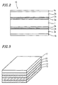
- Figure 2 is a sectional view of a liquid crystal display apparatus of the first example.
- Figure 3 is a perspective view illustrating a polarizer-integrated type substrate which can be used in the liquid crystal display apparatus of the first example.
- Figure 4 is a sectional view of a liquid crystal display apparatus of the second example of the invention.
- Figure 5 is a view illustrating the orientation of the liquid crystal layer generated in a liquid crystal display apparatus of a comparative example for the second example.
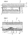
- Figure 6 is a sectional view of another liquid crystal display apparatus of the second example of the invention.
- Figure 7 is a sectional view of still further another liquid crystal display apparatus of the second example of the invention.
- FIG. 2 is a cross sectional view of a liquid crystal display apparatus 10 of the invention.
- the liquid crystal display apparatus 10 has substrates 3a and 3b which have transparent electrodes 2a and 2b on the opposing surfaces thereof, and a liquid crystal layer 1 interposed between the substrates 3a and 3b .
- the liquid crystal display apparatus 10 has polarizers 4a and 4b on surfaces of the substrates 3a and 3b which do not oppose each other.
- the liquid crystal display apparatus 10 of the invention changes its transmissivity to light, which passes from the polarizer 4a through the liquid crystal layer 1 to the polarizer 4b , depending on the, magnitude of the electric field applied to the liquid crystal layer 1 through the electrodes 2a and 2b similarly to the case of a liquid crystal display apparatus 10 of the prior art.
- the polarizers 4a and 4b are arranged so that the axes of absorption of the two polarizers 4a and 4b lie parallel or perpendicular to each other. More preferably, the axes of the absorption of the two polarizers 4a and 4b lie perpendicular to each other.
- the liquid crystal display apparatus 10 of the invention has organic polymer films 5a and 5b having glass transition points formed on the transparent electrode 2 of the substrates 3a and 3b .
- the liquid crystal layer 1 includes a chiral nematic liquid crystal produced by adding a small amount of chirality agent to a nematic liquid crystal.
- a chiral nematic liquid crystal produced by adding a small amount of chirality agent to a nematic liquid crystal.
- known materials used in twisted nematic (TN) liquid crystal display apparatuses and super-twisted nematic (STN) liquid crystal display apparatuses may be used.
- the chirality agent may be, for example, CB15, C15 made by BDH Co., Ltd., CN, R811, S811, R1011, S1011 made by E. Merck, CM-19, CM, CM-20, CM-21, CM-22 made by Chisso Co., Ltd.
- the ratio d/p of the thickness d of the liquid crystal layer 1 to the spontaneous helical pitch p of the chiral nematic liquid crystal is preferably from 0.1 to 1, and more preferably from 0.1 to 0.75, while 0.25 is the most preferable because it causes less coloration of the liquid crystal display apparatus.
- the substrates 3a and 3b may be any material, provided that it is transparent to visible light.
- the substrates 3a and 3b may be a known transparent material such as glass, acrylic resin and polycarbonate resin.
- the transparent electrodes 2a and 2b of tin oxide or ITO (indium-tin oxide) are formed on the substrates 3a and 3b by means of deposition, spottering, CVD or the like. Over these surfaces, the organic polymer films 5a and 5b having glass transition points are formed.
- the organic polymer films 5a and 5b may be of any type, it preferably has a glass transition point in a range from 40°C up to 150°C.
- a glass transition point below 40°C is not preferable because the liquid crystal orientation changes while driving the liquid crystal display apparatus at room temperature.
- a glass transition point higher than 150°C, on the other hand, is not preferable because the liquid crystal, sealing resin or the like of the liquid crystal layer 1 experiences changes during the heating process at a temperature above the glass transition point for the purpose of eliminating disturbances in the orientation.
- the organic polymer films 5a and 5b may be either amorphous, crystalline or partially crystalline polymers, provided that the films show an elasticity of rubber above the glass transition point.
- the elasticity of rubber referred to here means the ability to be stretched by at least 100% and return to almost the initial size when the external force is terminated.
- the organic polymer films 5a and 5b should be a partially crystalline polymer or a crosslinked polymer in order to fix the liquid crystal orientation at a temperature below the glass transition point.
- a resin which dissolves into the liquid crystal, is significantly colored is not suitable for the organic polymer films 5a and 5b .
- organic polymer films 5a and 5b polymethyl methacrylate, poly(t-butylmethacrylate), polycarbonate, polycyclohexylmethacrylate, polyethyleneterephthalate, materials based on polyurethane, poly(2-hydroxyethylmethacrylate), poly(isobornylmethacrylate), polyvinylalcohol and cellulose polymer, copolymers of these materials, or those which are partially crosslinked may be used, provided that the glass transition point is in a range from 40°C up to 150°C.
- materials based on polyurethane and especially, partially crosslinked thermoplastic polyurethane.
- Organic polymer films used for the invention must have the capability to align the liquid crystal in horizontal orientation.
- organic polymer films having an alkyl chain or a trifluoromethyl group in the side chain can be used even though they are known as a film having a high pre-tilt angle.
- a film made of polysiloxane is not suitable for an organic film of the invention because the film aligns the liquid crystal in a perpendicular orientation.
- a mixture of the organic polymer mentioned above and materials known as a conventional alignment film may be used for the invention.
- the mixture contains the above-mentioned organic polymer at 3% or more by weight.
- the organic polymer films 5a and 5b are formed by applying the organic polymer in the form of a solution onto the substrates 3a and 3b having the transparent electrodes 2a and 2b , then removing the solvent. Coating with the organic polymer may be carried out by a known method such as spin coating, printing or dipping.
- the organic polymer film having a glass transition point formed on the substrate must be heated to remove the solvent. While the heating temperature varies depending on the kind of solvent, heating on a hot plate at 100°C for one minute will suffice in the case in which N-methylpyrrolidone is used as the solvent.
- the thickness of the organic polymer films 5a and 5b is not limited, although the thickness is preferably within a range from 20 nm to 200 nm. A film thinner than 20 nm will not be capable of covering the entire surface uniformly, and a film thicker than 200 nm results in increased voltage drop by the film leading to poor display quality of the liquid crystal display apparatus.
- the organic polymer films 5a and 5b are formed on the surfaces of the substrates 3a and 3b whereon the transparent electrodes 2a and 2b are formed.
- the insulator layer may be made of any material, while silicon oxide and silicon nitride have better insulation performance and transparency.
- the organic polymer films 5a and 5b which have been formed do not need an orientation process such as rubbing.
- the two substrates 3a and 3b which have the organic polymer films 5a and 5b and the transparent electrodes 2a and 2b , are held to keep a proper space therebetween so that the organic polymer films 5a and 5b of the respective substrates oppose each other, and the liquid crystal layer 1 is interposed in the space.
- the liquid crystal layer 1 may be formed by a known method such as vacuum injection or liquid crystal dripping method.
- the two substrates are kept at a specified distance usually by arranging spherical particles made of glass or a synthetic resin between the substrates. It is preferable to bond the two substrates by means of an adhesive before or at the same time the liquid crystal is interposed therebetween. An epoxy resin is often used as the adhesive.
- the substrates 3a and 3b interposing the liquid crystal therebetween are kept at the NI point (nematic-isotropic point) of the liquid crystal or the glass transition point (Tg) of the organic polymer films 5a and 5b , whichever is higher. While the duration of time of keeping it at the temperature is not limited, about two hours may be sufficient in the case where a hot air drier is used. It is not desirable to keep the liquid crystal cell at a high temperature for too long a time, because it may cause part of the liquid crystal to decompose.
- the liquid crystal molecules adjacent to the organic polymer films 5a and 5b should be ideally aligned in a random direction having a predetermined pre-tilt angle. However, the liquid crystal molecules are actually adsorbed to the surface of the organic polymer films 5a and 5b in the direction into which the liquid crystal has been injected. The liquid crystal molecules are then aligned in random direction by keeping the liquid crystal cell at the NI point of the liquid crystal or the glass transition point of the organic polymer films 5a and 5b , whichever is higher. The regularity of the surface of the organic polymer films 5a and 5b caused by injection of the liquid crystal also disappear.
- the liquid crystal After cooling down the liquid crystal cell to the room temperature, the liquid crystal has a plurality of microscopic domains.
- Each of the plurality of the microscopic domains in the vicinity of the organic polymer films 5a and 5b has the liquid crystal molecules aligned uniformly, and the liquid crystal molecules in different microscopic regions are arranged in different directions with respect to one another. Accordingly, in the liquid crystal display apparatus of the invention, disturbance in the orientation of the liquid crystal molecules disappears.
- the transparent electrodes 2a and 2b made of ITO (indium-tin oxide) were formed on the entire surface of the substrates 3a and 3b having an area of 5 cm x 6 cm.
- a nitrobenzene solution of polyethyleneterephthalate (made by Scientific Polymer Products Corp.) having glass transition point at 81°C was applied onto the surfaces of the structure of the substrates 3a and 3b , having the transparent electrodes 2a and 2b , and dried thereby to form the organic polymer films 5a and 5b each 70 nm thick.
- the polyethyleneterephthalate in the form of a film 50 ⁇ m thick was stretched by 200% or greater at a temperature of glass transition point or higher, and showed the elasticity of rubber. This film also showed a peak in X-ray diffraction, indicating that it was partially crystallized.
- the substrates 3a and 3b were arranged so that the organic polymer films 5a and 5b oppose each other.
- a nematic liquid crystal (product name ZLI2419 made by E. Merck) having an NI point at 64°C was sealed between the substrates by a vacuum injection process to form the liquid crystal cell having the liquid crystal layer 1 .
- the liquid crystal injected in this process was one with a chirality agent (product name R811 made by E. Merck) added thereto to obtain a liquid crystal pitch of 30 ⁇ m.
- the liquid crystal cell was kept in a hot air drier at a temperature of 120°C for one hour, then allowed to cool down at room temperature.
- the liquid crystal cell was interposed between the two polarizers 4a and 4b which were arranged so that the polarization axes lie at right angles to each other, thereby to obtain the liquid crystal display apparatus 10 .
- the transparent electrodes 2a and 2b made of ITO (indium-tin oxide) were formed on the entire surface of the substrates 3a and 3b having an area of 5 cm x 6 cm.
- Dimethylformamide solution of polycarbonate (made by Scientific Polymer Products Corp.) having a glass transition point at 150°C and a mean molecular weight of 64,000 was applied onto the surfaces of the structure of the substrates 3a and 3b having the transparent electrodes 2a and 2b , and dried thereby to form the organic polymer films 5a and 5b each 70 nm thick.
- the polycarbonate in the form of a film 50 ⁇ m thick was stretched by 200% or greater at a temperature of glass transition point or higher, and showed the elasticity of rubber. This film also showed a peak in X-ray diffraction, indicating that it is partially crystallized.
- the substrates 3a and 3b were arranged so that the organic polymer films 5a and 5b oppose each other.
- a nematic liquid crystal (product name ZLI2419 made by E. Merck) having an NI point at 64°C was sealed between the substrates by a vacuum injection process to form the liquid crystal cell having the liquid crystal layer 1 .
- the liquid crystal injected in this process was one with a chirality agent (product name R811 made by E. Merck) added thereto to obtain a liquid crystal pitch of 30 ⁇ m.
- the liquid crystal cell was kept in a hot air drier at a temperature of 155°C for one hour, then allowed to cool down at room temperature.
- the liquid crystal cell was interposed between the two polarizers 4a and 4b which were arranged so that the polarization axes lie at right angles to each other, thereby to obtain the liquid crystal display apparatus 10 .
- the transparent electrodes 2a and 2b made of ITO (indium-tin oxide) were formed on the entire surface of the substrates 3a and 3b having an area of 5 cm x 6 cm.
- thermoplastic polyurethane resin product name Diari MS5500 made by Mitsubishi Heavy Industries Ltd.
- a glass transition point at 55°C was applied onto the surfaces of the structure of the substrates 3a and 3b having the transparent electrodes 2a and 2b , and dried thereby to form the organic polymer films 5a and 5b each 70 nm thick.
- the thermoplastic polyurethane in the form of a film 50 ⁇ m thick was stretched by 400% or greater at a temperature at the glass transition point or higher, and showed the elasticity of rubber. This film also showed a peak in X-ray diffraction, indicating that it was partially crystallized.
- the substrates 3a and 3b were arranged so that the organic polymer films 5a and 5b oppose each other.
- a nematic liquid crystal (product name ZLI2419 made by E. Merck) having an NI point at 64°C was sealed between the substrates by a vacuum injection process to form the liquid crystal cell having the liquid crystal layer 1 .
- the liquid crystal injected in this process was one with a chirality agent (product name R811 made by E. Merck) added thereto to obtain a liquid crystal pitch of 30 ⁇ m.
- the liquid crystal cell was kept in a hot air drier at a temperature of 80°C for one hour, then allowed to cool down at room temperature.
- the liquid crystal cell was interposed between the two polarizers 4a and 4b which were arranged so that the polarization axes lie at right angles to each other, thereby to obtain the liquid crystal display apparatus 10 .
- the transparent electrodes 2a and 2b made of ITO (indium-tin oxide) were formed on the entire surface of the substrates 3a and 3b having an area of 5 cm x 6 cm.
- thermoplastic polyurethane resin product name Diari MS5500 made by Mitsubishi Heavy Industries Ltd.
- polyimide product name AL5417 made by Japan Synthetic Rubber Co., Ltd.
- the thermoplastic polyurethane is added to the polyimide by a weight ratio of 1:9.
- the substrates 3a and 3b were arranged so that the organic polymer films 5a and 5b oppose each other.
- a nematic liquid crystal (product name ZLI2419 made by E. Merck) having an NI point at 64°C was sealed between the substrates by a vacuum injection process to form the liquid crystal cell having the liquid crystal layer 1 .
- the liquid crystal injected in this process was one with a chirality agent (product name R811 made by E. Merck) added thereto to obtain a liquid crystal pitch of 30 ⁇ m.
- the liquid crystal cell was kept in a hot air drier at a temperature of 80°C for one hour, then allowed to cool down at room temperature.
- the liquid crystal cell was interposed between the two polarizers 4a and 4b which were arranged so that the polarization axes lie at right angles to each other, thereby to obtain the liquid crystal display apparatus 10 .
- the transparent electrodes 2a and 2b made of ITO (indium-tin oxide) were formed on the entire surface of the substrates 3a and 3b having an area of 5 cm x 6 cm.
- N-methylpyrrolidone solution of partially crosslinked urethane resin (product name Texin 192A made by Mobay Chemical Co., Ltd.) having glass transition point at 82°C was applied onto the surfaces of the structure of the substrates 3a and 3b having the transparent electrodes 2a and 2b , and dried thereby to form the organic polymer films 5a and 5b each 70 nm thick.
- the thermoplastic polyurethane in the form of a film 50 ⁇ m thick was stretched by 400% or greater at a temperature of glass transition point or higher, and showed the elasticity of rubber. This film also showed a peak in X-ray diffraction, indicating that it was partially crystallized.
- the substrates 3a and 3b were arranged so that the organic polymer films 5a and 5b oppose each other.
- a nematic liquid crystal (product name ZLI2419 made by E. Merck) having an NI point at 64°C was sealed between the substrates by a vacuum injection process to form the liquid crystal cell having the liquid crystal layer 1 .
- the liquid crystal injected in this process was one with a chirality agent (product name R811 made by E. Merck) added thereto to obtain a liquid crystal pitch of 30 ⁇ m.
- the liquid crystal cell was kept in a hot air drier at a temperature of 100°C for one hour, then allowed to cool down at room temperature.
- the liquid crystal cell was interposed between the two polarizers 4a and 4b , which were arranged so that the polarization axes lie at right angles to each other, thereby to obtain the liquid crystal display apparatus 10 .
- a polarizer-integrated substrate was used instead of the glass substrates 3a and 3b of the embodiment 1-3.
- a polarizer-integrated substrate having a polarizer 13 , polyethersulphon films 14 and 15 arranged to interpose the polarizer 13 , an undercoat layer 16 provided on the polyethersulphon films 14 and a transparent electrode (ITO) layer 17 formed on the undercoat layer 16 were used.
- ITO transparent electrode
- CST-7100 made by Sumitomo Bakelite Co., Ltd., for example, may be used.
- the polyethersulphon films 14 and 15 have optical isotropy.
- the polarizer 13 , the polyethersulphon films 14 and 15 , and the undercoat layer 16 correspond to the substrates 3a and the polarizer 4a , or the substrates 3b and the polarizer 4b shown in Figure 2 .
- the transparent electrode (ITO) layer 17 can be formed into a desired configuration to make transparent electrodes 2a and 2b .
- the organic polymer layer 5a or 5b shown in Figure 2 , was installed to cover the undercoat layer 16 whereon the transparent electrode (ITO) layer 17 was partially formed, thereby to obtain a liquid crystal display apparatus.
- ITO transparent electrode
- an N-methylpyrrolidone solution of polyimide varnish (product name LQ-S100 made by Hitachi Chemical Co., Ltd.) having glass transition point at 266°C was applied. After evaporating the solvent by means of a hot plate, the film was left to harden at 250°C for one hour, thereby forming a polyimide film 70 nm thick and making a liquid crystal display apparatus. When heated to 280°C, the film turned black and decomposed, therefore it was considered to have no elasticity of rubber. After injecting the liquid crystal, the liquid cell was not kept at a high temperature.
- an N-methylpyrrolidone solution of polyimide varnish (product name LQ-S100 made by Hitachi Chemical Co., Ltd.) having a glass transition point at 266°C was applied. After evaporating the solvent by means of a hot plate, the film was left to harden at 250°C for one hour, thereby forming a polyimide film 70 nm thick and making a liquid crystal display apparatus. After injecting the liquid crystal, the liquid cell was kept in a hot air drier at a temperature of 80°C for one hour, then allowed to cool down at room temperature.
- polyimide varnish product name LQ-S100 made by Hitachi Chemical Co., Ltd.
- an N-methylpyrrolidone solution of polyimide varnish (product name LQ-S100 made by Hitachi Chemical Co., Ltd.) having a glass transition point at 266°C was applied. After evaporating the solvent by means of a hot plate, the film was left to harden at 250°C for one hour, thereby forming a polyimide film 70 nm thick and a liquid crystal display apparatus was made.
- the liquid cell After injecting the liquid crystal, the liquid cell was kept in a hot air drier at a temperature of 280°C for one hour, and the liquid crystal cell broke with the liquid crystal scattering to the out-side, unable to fabricate a liquid cell.
- the liquid crystal cells obtained in the embodiments 1-1 through 1-5 and comparative examples 1-1 and 1-2 were compared by studying the orientation of each liquid crystal. Orientation was checked to see whether orientation defect is found or not by visual observation with no voltage being applied. Results are shown in Table 1.
- the liquid crystal display apparatus of the invention made by using an organic polymer film having a glass transition point in a range from 40°C up to 150°C or an organic polymer film which shows the elasticity of rubber at temperatures above the glass transition point has good liquid orientation and shows no non-uniformity in the liquid crystal orientation in the direction of flow which may be caused by liquid crystal injection.
- Table 1 Glass transition point(°C) Rubber elasticity Appearance of display Example 1-1 81 Yes Uniform Example 1-2 150 Yes Uniform Example 1-3 55 Yes Uniform Example 1-4 No Uniform Example 1-5 82 Yes Uniform Comparative Example 1-1 266 No Remarkable disturbance Comparative Example 1-2 266 No Disturbance
- a liquid crystal display apparatus 20 of the second example of the invention will be described below with reference to Figure 4 .
- the liquid crystal display apparatus 20 has an upper glass substrate 21 , a lower glass substrate 22 and a chiral nematic liquid crystal layer 23 interposed between the two substrates.
- segment electrodes 24 and common electrodes 25 are formed, respectively.
- the segment electrodes 24 and common electrodes 25 are strip shapes having a width of 80 ⁇ m, and the segment electrodes 24 elongate in the direction perpendicular to the direction in which the common electrodes 25 elongate. Therefore, transverse cross sections of the common electrodes 25 and longitudinal cross section of the segment electrodes 24 are shown in Figure 4 .
- Polyimide films 26 and 27 are formed on the upper glass substrate 21 and the lower glass substrate 22 in such a manner as to cover the segment electrodes 24 and the common electrodes 25 .
- the upper glass substrate 21 and the lower glass substrate 22 are kept at such a distance as to hold the liquid crystal layer 23 by a spacer 33 , and the liquid crystal layer 23 is sealed by a sealant 28 .
- the upper glass substrate 21 and the lower glass substrate 22 have polarizers 29 and 30 attached on the surfaces thereof which do not oppose each other.
- the polyimide films 26 and 27 are not processed by rubbing.
- the polyimide films 26 and 27 also have ultraviolet-irradiated regions 31 and ultraviolet non-irradiated regions 32 .
- the ultraviolet irradiated regions 31 of the polyimide films 26 and 27 have chemical and physical properties different from those of the ultraviolet non-irradiated regions 32 such that polyimide is oxidized by ultraviolet ray or side chains of the molecule is cut off. Therefore, the pre-tilt angle of the liquid crystal molecules in contact with the ultraviolet-irradiated regions 31 is different from the pre-tilt angle of the liquid crystal molecules in contact with the ultraviolet non-irradiated regions 32 .
- the surface conditions for orientation of the liquid crystal molecules discontinues at the boundaries between the ultraviolet-irradiated regions 31 and the ultraviolet non-irradiated regions 32 . Domains formed in the liquid crystal layer are therefore made to be small by the discontinuity of the orientation, which reduces rough appearance of the liquid crystal display to the eye.
- Such a discontinuity of the orientation of the liquid crystal molecules is so effective to reduce rough appearance to the eye, as long as such a discontinuity of the orientation of the liquid crystal molecules is provided on at least one polyimide film.
- the liquid crystal display apparatus 20 is fabricated in the following processes.
- an ITO (indium-tin oxide) film having sheet resistance of about 30 ⁇ /sq. formed on the upper glass substrate 21 is patterned by photolithography, to obtain the segment electrodes 24 comprising 64 stripes.
- the common electrodes 25 comprising 64 stripes are also formed on the lower glass substrate 22 in a similar process.
- the segment electrode and the common electrode are arranged to lie perpendicular to each other.
- the polyimide films 26 and 27 each 80 nm thick are formed in a printing process on such glass substrates 21 and 22 as described above.
- RN-7511 (Nissan Chemical Industries Ltd.) are used for the thin polyimide film of this example.
- the thin polyimide film has a function to align the liquid crystal molecules in an orientation at a pre-tilt angle near the normal direction of the glass substrate surface. Then after forming a mask pattern (not shown in the drawing), having an aperture only at a position where the common electrodes 25 are located, on the polyimide film 27 , the polyimide film 27 was irradiated with the light of a high-pressure mercury lamp through a mask pattern for five minutes. Intensity of light at the irradiated surface was 40 mW/cm2. On the irradiated polyimide film, the liquid crystal molecules are aligned in orientation parallel or at a slight pre-tilt angle to the substrate.
- such a mask pattern (not shown in the drawing), that has an aperture only at a position where the segment electrodes 24 are located, was formed on the polyimide film 26 of the upper glass substrate 21 , then the polyimide film 26 was irradiated with the light of the high-pressure mercury lamp through a mask pattern for five minutes. Intensity of light at the irradiated surface was 40 mW/cm2.
- Spherical spacers 33 made of a plastic 5 ⁇ m in diameter (Micro-pearl made by Sekisui Fine Co., Ltd.) were uniformly dispersed over the lower glass substrate 22 .
- a thermosetting sealant 28 (Struct-bond made by Mitsui Toatsu Chemicals, Inc.) was formed by printing on the periphery of the upper glass substrate 21 leaving an inlet for liquid crystal injection.
- the upper and lower glass substrates 21 and 22 were placed one on another and bonded so that the segment electrodes 24 and the common electrodes 25 lie perpendicular to each other, and the sealant 28 was let to harden completely at a specified temperature.
- Birefringence ⁇ n and the cell gap d preferably satisfy an inequality 0.45 ⁇ m ⁇ ⁇ n x d ⁇ 1 ⁇ m.
- the chiral nematic liquid crystal fabricated under such conditions as described above was heated to turn the liquid crystal isotropic, then the liquid crystal was injected into the space between the glass substrates 21 and 22 by vacuum injection method. At this time, the glass substrates 21 and 22 are also heated to a temperature above the nematic-isotropic phase transition temperature (NI point) of the chiral nematic liquid crystal. After forming the chiral nematic liquid crystal layer 23 , the liquid crystal cell was gradually cooled dawn and the inlet for liquid crystal injection was sealed with a sealing resin.
- NI point nematic-isotropic phase transition temperature
- liquid crystal display apparatus 20 fabricated as described above, because the pre-tilt angle of the liquid crystal molecules differs between the ultraviolet-irradiated region and ultraviolet non-irradiated region, such a large liquid crystal domain is not formed as extending between the ultraviolet-irradiated region and ultraviolet non-irradiated region.
- both the ultraviolet-irradiated region and the ultraviolet non-irradiated region are smaller. Specifically, it is preferable that either region is not greater than 50 ⁇ m x 50 ⁇ m. In order to form such microscopic regions, it is preferable that the mask pattern, used in the irradiation of ultraviolet light, has an aperture smaller than the segment electrodes 24 or the common electrodes 25 .
- the ultraviolet-irradiated regions and the ultraviolet non-irradiated regions can be formed on the polyimide films 26 and 27 by irradiating the films with ultraviolet light from the upper and lower glass substrates 21 and 22 sides with the shielding film as a mask. Such a method simplifies the manufacturing process.
- a liquid crystal display apparatus having polyimide film without the ultraviolet-irradiated region formed thereon was fabricated by using PSI-A-2201 (made by Chisso Co., Ltd.) as the thin polyimide film.
- Figure 5 is an oblique view drawing illustrative of the microscopic orientation in the pixel at an OFF voltage when the liquid crystal display apparatus is driven with 1/4 duty.
- thick line 41 represents the major axis of a liquid crystal molecule (director).
- disclination lines 46 were observed caused by the difference in the directions of directors between domains.
- the liquid crystal molecules are put into orientation in a state similar to amorphous material by the intermolecular force, generating a plurality of domains.
- the liquid crystal molecules show a state of orientation with a twist corresponding to the preset value of d/p between the upper and lower substrates.
- the liquid crystal molecules show an orientation twisted 90° between the upper and lower substrates. In this case, it is presumed that the incident light exits from the liquid crystal layer being elliptically polarized by the birefringent effect of the liquid crystal layer.
- the liquid crystal molecules in each domain turn from the twisted orientation to splay orientation, and therefore clear disclination lines accompanying deformation appear in the liquid crystal layer (bulk).
- the liquid crystal molecules are aligned in such an orientation so that the director is parallel to the direction of the electric field, and so that the incident light transmits, through the liquid crystal layer in almost linearly polarized state, and is cut by the exit polarizer to create dark state.
- the clear disclination does not disappear completely.
- a liquid crystal display apparatus 50 shown in Figure 6 has positive photoresist films 36 and 37 instead of the polyimide films 26 and 27 of the liquid crystal display apparatus 20 of the example 2-1.
- the other components are the same as those of the liquid crystal display apparatus 20 , and therefore description thereof will be omitted while detailed description will be given to the positive photoresist films 36 and 37 .
- the upper and lower glass substrates 21 and 22 with the segment electrode 24 and the common electrode 25 were formed, respectively, thereon and were coated with a positive photoresist based on novolac resin (made by Tokyo Ohka Kogyo Co., Ltd.) by a method similar to the example 2-1 so as to form photoresist films having a thickness of 2 ⁇ m, and were dried in an oven at 160°C for 30 minutes. Then the positive photoresist film was irradiated with the light of a high-pressure mercury lamp for five minutes via a light-intercepting mask intercepting the light only at the portions of the electrodes. Intensity of radiation at the irradiated surface was 100 mW/cm2. After irradiation, exposed portions (namely the resist film in portions other than the electrodes) were dissolved and removed by using a weakly alkaline developer solution to form positive films 36 and 37 on the glass substrates 21 and 22 , respectively.
- a positive photoresist based on novolac resin made by Tokyo
- FIG. 7 is a sectional drawing explanatory of a so-called active liquid crystal display apparatus 60 provided with a thin film transistor (referred to as TFT hereafter) for each pixel of the liquid crystal display apparatus described in the example 2-1.
- TFT thin film transistor
- the lower glass substrate 61 is provided with a TFT 62 and a pixel electrode 63 formed thereon.
- the TFT 62 has a gate electrode 64 , a gate insulator film 65 , an amorphous silicon layer 66 , a source electrode 67 and a drain electrode 68 .
- the drain electrode 68 is connected to the pixel electrode 63 .
- An alignment film 69 is formed on the lower glass substrate 61 in such a manner as to cover the TFT 62 and the pixel electrode 63 .
- the alignment film 69 includes an ultraviolet-irradiated region 69b and an ultraviolet non-irradiated region 69a .
- an upper glass electrode 70 is provided with a light intercepting layer 71 , and a common electrode 72 is provided on the upper glass substrate 70 to cover the light intercepting layer 71 . Further an alignment film 73 is provided over the entire surface of the upper glass electrode 70 to cover the common electrode 72 . A polymer/liquid crystal composite layer 74 is interposed between the upper glass electrode 70 and the lower glass electrode 61 .
- a chrome layer is formed on the lower glass substrate 61 by electron beam deposition, and the gate electrode 64 is formed by photo-etching.
- the gate insulator film 65 made of silicon nitride 200 nm thick, is formed by plasma CVD method, over which an amorphous silicon layer 66 having a thickness of 60 nm is formed by the plasma CVD method which is then processed into a desired shape by photo-etching.
- a chrome layer is formed over the entire surface by sputtering from which the drain electrode 68 and the source electrode 67 were formed by photo-etching.
- a thin polyimide film of RN-7511 (Nissan Chemical Industries Ltd.) covering the entire surface is formed.
- the thin polyimide film has the function to align the liquid crystal molecules in an orientation at a pre-tilt angle near the normal direction of the glass substrate surface.
- a light intercepting layer 71 made of chrome is formed in a portion opposing the TFT 62 on the upper glass substrate 70 and the common electrode 72 made of ITO is formed over the entire surface.
- nylon-6 is formed on the upper glass substrate 70 .
- an acid anhydride-hardening type epoxy resin with glass fibers 5 ⁇ m in diameter dispersed therein, is printed in a width of 0.2 mm along the perimeter except for one edge where a space 5 mm wide is left at the center of the edge.
- a chiral nematic liquid crystal is prepared by adding a chirality agent to a nematic liquid crystal similar to that of the example 1 so that the d/p becomes 0.25, and the chiral nematic liquid crystal is injected at 120°C, a temperature above the NI point, to fabricate the liquid crystal display apparatus.
- the display is completed by attaching two polarizers on the front and back of the liquid crystal display apparatus so that the axes of absorption lay perpendicular to each other.
- transmission type liquid crystal display apparatuses are taken as examples in the above description of the invention, the invention is not limited to the transmission type and provides high quality of display when applied to a liquid crystal display apparatus of reflection type by providing a reflector on the surface of one polarizer.
- such examples are described in the above embodiments as breaking the continuity in each pixel without specifying a region where the surface condition is changed, the structure can be made even finer by forming regions of different surface conditions in the electrode. Also because the rubbing process is not necessary, a decrease in the yield of production due to rubbing can be prevented, having a great effect of reducing the manufacturing process.
Landscapes
- Physics & Mathematics (AREA)
- Nonlinear Science (AREA)
- Spectroscopy & Molecular Physics (AREA)
- Mathematical Physics (AREA)
- Chemical & Material Sciences (AREA)
- Crystallography & Structural Chemistry (AREA)
- General Physics & Mathematics (AREA)
- Optics & Photonics (AREA)
- Liquid Crystal (AREA)
Applications Claiming Priority (15)
| Application Number | Priority Date | Filing Date | Title |
|---|---|---|---|
| JP193357/93 | 1993-08-04 | ||
| JP19335793 | 1993-08-04 | ||
| JP19335793A JP2940351B2 (ja) | 1993-08-04 | 1993-08-04 | 液晶表示パネル |
| JP195715/93 | 1993-08-06 | ||
| JP19571593 | 1993-08-06 | ||
| JP5195715A JPH0749500A (ja) | 1993-08-06 | 1993-08-06 | 液晶表示素子およびその製造法 |
| JP218330/93 | 1993-09-02 | ||
| JP21833093 | 1993-09-02 | ||
| JP21833093 | 1993-09-02 | ||
| JP25048093 | 1993-10-06 | ||
| JP5250480A JP2940359B2 (ja) | 1993-10-06 | 1993-10-06 | 液晶表示パネル |
| JP250480/93 | 1993-10-06 | ||
| JP30512493 | 1993-12-06 | ||
| JP5305124A JPH07159784A (ja) | 1993-12-06 | 1993-12-06 | 液晶表示パネルの製造方法 |
| JP305124/93 | 1993-12-06 |
Publications (3)
| Publication Number | Publication Date |
|---|---|
| EP0637771A2 true EP0637771A2 (fr) | 1995-02-08 |
| EP0637771A3 EP0637771A3 (fr) | 1995-06-28 |
| EP0637771B1 EP0637771B1 (fr) | 2001-07-11 |
Family
ID=27529076
Family Applications (1)
| Application Number | Title | Priority Date | Filing Date |
|---|---|---|---|
| EP94112123A Expired - Lifetime EP0637771B1 (fr) | 1993-08-04 | 1994-08-03 | Méthode de fabrication d'un dispositif d'affichage à cristal liquide comprenant un film d'alignement d'orientation aléatoire |
Country Status (3)
| Country | Link |
|---|---|
| US (1) | US5446569A (fr) |
| EP (1) | EP0637771B1 (fr) |
| DE (1) | DE69427668T2 (fr) |
Cited By (1)
| Publication number | Priority date | Publication date | Assignee | Title |
|---|---|---|---|---|
| WO2003046652A1 (fr) * | 2001-11-28 | 2003-06-05 | Sharp Kabushiki Kaisha | Dispositif de decalage d'image, affichage d'image, affichage a cristaux liquides, et affichage de projection d'image |
Families Citing this family (24)
| Publication number | Priority date | Publication date | Assignee | Title |
|---|---|---|---|---|
| US5648829A (en) * | 1994-02-15 | 1997-07-15 | Kyocera Corporation | Method for fabricating a liquid crystal display including irradiating an alignment film with UV light |
| JP3732242B2 (ja) * | 1994-02-18 | 2006-01-05 | シャープ株式会社 | 液晶表示装置 |
| US5710611A (en) * | 1994-11-17 | 1998-01-20 | Nec Corporation | Liquid crystal display apparatus preventing image on screen from influences of disclination line |
| JP3698749B2 (ja) * | 1995-01-11 | 2005-09-21 | 株式会社半導体エネルギー研究所 | 液晶セルの作製方法およびその作製装置、液晶セルの生産システム |
| JPH08201761A (ja) * | 1995-01-26 | 1996-08-09 | Sharp Corp | 液晶表示素子 |
| US5726729A (en) * | 1995-08-01 | 1998-03-10 | Casio Computer Co., Ltd. | Liquid crystal display device |
| JPH09281508A (ja) * | 1996-04-12 | 1997-10-31 | Semiconductor Energy Lab Co Ltd | 液晶表示装置およびその作製方法 |
| US5739883A (en) * | 1996-08-30 | 1998-04-14 | Nan Ya Technology Corporation | Manufacturing method and structure for aligner of liquid crystal display |
| US6437844B1 (en) * | 1996-09-04 | 2002-08-20 | Matsushita Electric Industrial Co., Ltd. | Liquid crystal display device and associated fabrication method |
| JP3460527B2 (ja) * | 1996-10-04 | 2003-10-27 | シャープ株式会社 | 液晶表示装置 |
| US5877835A (en) * | 1997-02-24 | 1999-03-02 | Motorola, Inc. | Method of manufacturing a liquid crystal display |
| JP2001312222A (ja) * | 2000-02-25 | 2001-11-09 | Sharp Corp | アクティブマトリクス基板およびその製造方法並びに該基板を用いた表示装置および撮像装置 |
| US6767609B2 (en) * | 2000-09-15 | 2004-07-27 | 3M Innovative Properties Company | Perforated film constructions for backlit signs |
| US6791648B2 (en) * | 2001-03-15 | 2004-09-14 | Seiko Epson Corporation | Liquid crystal device, projection display device and, manufacturing method for substrate for liquid crystal device |
| US7106307B2 (en) * | 2001-05-24 | 2006-09-12 | Eastman Kodak Company | Touch screen for use with an OLED display |
| KR20030033874A (ko) * | 2001-10-25 | 2003-05-01 | 엘지.필립스 엘시디 주식회사 | 배향막 인쇄장치와 그를 이용한 인쇄방법 |
| GB2411735A (en) * | 2004-03-06 | 2005-09-07 | Sharp Kk | Control of liquid crystal alignment in an optical device |
| WO2008115765A1 (fr) * | 2007-03-16 | 2008-09-25 | Pathogen Systems, Inc. | Procédé pour aligner des cristaux liquides |
| US10642087B2 (en) | 2014-05-23 | 2020-05-05 | Eyesafe, Llc | Light emission reducing compounds for electronic devices |
| US10955697B2 (en) | 2018-11-28 | 2021-03-23 | Eyesafe Inc. | Light emission modification |
| US11810532B2 (en) | 2018-11-28 | 2023-11-07 | Eyesafe Inc. | Systems for monitoring and regulating harmful blue light exposure from digital devices |
| US12321060B1 (en) | 2018-11-28 | 2025-06-03 | Eyesafe Inc. | Color filter enhancements for display devices |
| US11592701B2 (en) | 2018-11-28 | 2023-02-28 | Eyesafe Inc. | Backlight unit with emission modification |
| CN115226403A (zh) * | 2021-02-17 | 2022-10-21 | 人眼安全公司 | 具有发射修改的背光单元 |
Family Cites Families (10)
| Publication number | Priority date | Publication date | Assignee | Title |
|---|---|---|---|---|
| US4878742A (en) * | 1986-08-04 | 1989-11-07 | Canon Kabushiki Kaisha | Liquid crystal optical modulator |
| DE3774977D1 (de) * | 1986-09-12 | 1992-01-16 | Hoffmann La Roche | Fluessigkristallanzeige. |
| US4906074A (en) * | 1987-09-28 | 1990-03-06 | Semiconductor Energy Laboratory Co., Ltd. | FLC liquid crystal electro-optical device having microdomains within pixels |
| JPH02130521A (ja) * | 1988-11-11 | 1990-05-18 | Nippon I B M Kk | ツイステッド・ネマチック液晶表示装置 |
| JP2502802B2 (ja) * | 1990-10-15 | 1996-05-29 | インターナシヨナル・ビジネス・マシーンズ・コーポレーシヨン | 液晶表示装置 |
| DE69221102T2 (de) * | 1991-12-20 | 1998-01-08 | Fujitsu Ltd | Flüssigkristall-Anzeigevorrichtung mit verschiedenen aufgeteilten Orientierungsbereichen |
| JP2748951B2 (ja) * | 1992-07-15 | 1998-05-13 | 富士通株式会社 | 液晶表示装置 |
| JP2787875B2 (ja) * | 1992-07-23 | 1998-08-20 | 富士通株式会社 | 電界制御複屈折効果型液晶表示装置 |
| US5453862A (en) * | 1992-09-04 | 1995-09-26 | Stanley Electric Co., Ltd. | Rubbing-free (chiral) nematic liquid crystal display |
| US5530573A (en) * | 1993-05-27 | 1996-06-25 | Sharp Kabushiki Kaisha | Multiple domain liquid crystal display having a cell thickness divided by helical pitch equal to 1/8 or less |
-
1994
- 1994-08-03 EP EP94112123A patent/EP0637771B1/fr not_active Expired - Lifetime
- 1994-08-03 DE DE69427668T patent/DE69427668T2/de not_active Expired - Fee Related
- 1994-08-04 US US08/285,862 patent/US5446569A/en not_active Expired - Fee Related
Cited By (2)
| Publication number | Priority date | Publication date | Assignee | Title |
|---|---|---|---|---|
| WO2003046652A1 (fr) * | 2001-11-28 | 2003-06-05 | Sharp Kabushiki Kaisha | Dispositif de decalage d'image, affichage d'image, affichage a cristaux liquides, et affichage de projection d'image |
| US7277140B2 (en) | 2001-11-28 | 2007-10-02 | Sharp Kabushiki Kaisha | Image shifting device, image display, liquid crystal display, and projection image display |
Also Published As
| Publication number | Publication date |
|---|---|
| EP0637771B1 (fr) | 2001-07-11 |
| DE69427668D1 (de) | 2001-08-16 |
| EP0637771A3 (fr) | 1995-06-28 |
| DE69427668T2 (de) | 2002-06-20 |
| US5446569A (en) | 1995-08-29 |
Similar Documents
| Publication | Publication Date | Title |
|---|---|---|
| US5446569A (en) | Liquid crystal display apparatus having a random orientation alignment film and a method for producing the same | |
| US6175399B1 (en) | Reflective type liquid crystal display device having a diffusion layer of phase separated liquid crystal and polymer | |
| JP2930496B2 (ja) | 液晶表示素子及びその製造方法 | |
| KR0166109B1 (ko) | 액정표시소자 및 그의 제조방법 | |
| Toko et al. | Amorphous twisted nematic–liquid‐crystal displays fabricated by nonrubbing showing wide and uniform viewing‐angle characteristics accompanying excellent voltage holding ratios | |
| US5453862A (en) | Rubbing-free (chiral) nematic liquid crystal display | |
| JPH09160042A (ja) | 液晶表示素子 | |
| CN1285050A (zh) | 双稳向列相液晶装置 | |
| JPH08122750A (ja) | 液晶電気光学装置、それを利用した投射型表示装置及びそれらの駆動方法 | |
| JP2621110B2 (ja) | 液晶表示素子とその製造方法 | |
| JP3031812B2 (ja) | 液晶表示装置 | |
| JP3937587B2 (ja) | 液晶素子 | |
| EP0610924B1 (fr) | Dispositif d'affichage à cristal liquide avec structure à multi-domaines | |
| US6111632A (en) | Liquid crystalline material operable with low voltage and liquid crystal display panel using the same and liquid crystal display apparatus and manufacturing method of the apparatus | |
| JP3026901B2 (ja) | 液晶表示パネル | |
| US20070146599A1 (en) | Liquid crystal display device and method for manufacturing the same | |
| JPH07120764A (ja) | 液晶表示パネル及びその製造方法 | |
| JP3404467B2 (ja) | 液晶表示装置 | |
| JP3059630B2 (ja) | 液晶表示パネル及びその製造方法 | |
| JP2809980B2 (ja) | 液晶表示素子とその製造方法 | |
| JP2940359B2 (ja) | 液晶表示パネル | |
| JPH09160022A (ja) | 液晶電気光学装置 | |
| JP2948075B2 (ja) | 液晶表示パネルおよびその製造方法 | |
| JP3063553B2 (ja) | 液晶パネルの製造方法 | |
| JP2940351B2 (ja) | 液晶表示パネル |
Legal Events
| Date | Code | Title | Description |
|---|---|---|---|
| PUAI | Public reference made under article 153(3) epc to a published international application that has entered the european phase |
Free format text: ORIGINAL CODE: 0009012 |
|
| AK | Designated contracting states |
Kind code of ref document: A2 Designated state(s): DE FR GB NL |
|
| 17P | Request for examination filed |
Effective date: 19950104 |
|
| PUAL | Search report despatched |
Free format text: ORIGINAL CODE: 0009013 |
|
| RIN1 | Information on inventor provided before grant (corrected) |
Inventor name: KURAI, HISAKO Inventor name: KOSAKO, SHINYA Inventor name: MIZUNO, HIROAKI Inventor name: MOCHIZUKI, HIDEAKI Inventor name: SATO, SHIGEHIRO Inventor name: IWAI, YOSHIO |
|
| AK | Designated contracting states |
Kind code of ref document: A3 Designated state(s): DE FR GB NL |
|
| 17Q | First examination report despatched |
Effective date: 19980211 |
|
| GRAG | Despatch of communication of intention to grant |
Free format text: ORIGINAL CODE: EPIDOS AGRA |
|
| RTI1 | Title (correction) |
Free format text: METHOD OF PRODUCING A LIQUID CRYSTAL DISPLAY APPARATUS HAVING A RANDOM ORIENTATION ALIGNMENT FILM |
|
| GRAG | Despatch of communication of intention to grant |
Free format text: ORIGINAL CODE: EPIDOS AGRA |
|
| GRAH | Despatch of communication of intention to grant a patent |
Free format text: ORIGINAL CODE: EPIDOS IGRA |
|
| GRAH | Despatch of communication of intention to grant a patent |
Free format text: ORIGINAL CODE: EPIDOS IGRA |
|
| GRAA | (expected) grant |
Free format text: ORIGINAL CODE: 0009210 |
|
| AK | Designated contracting states |
Kind code of ref document: B1 Designated state(s): DE FR GB NL |
|
| REF | Corresponds to: |
Ref document number: 69427668 Country of ref document: DE Date of ref document: 20010816 |
|
| ET | Fr: translation filed | ||
| REG | Reference to a national code |
Ref country code: GB Ref legal event code: IF02 |
|
| PLBE | No opposition filed within time limit |
Free format text: ORIGINAL CODE: 0009261 |
|
| STAA | Information on the status of an ep patent application or granted ep patent |
Free format text: STATUS: NO OPPOSITION FILED WITHIN TIME LIMIT |
|
| 26N | No opposition filed | ||
| PGFP | Annual fee paid to national office [announced via postgrant information from national office to epo] |
Ref country code: GB Payment date: 20030730 Year of fee payment: 10 |
|
| PGFP | Annual fee paid to national office [announced via postgrant information from national office to epo] |
Ref country code: FR Payment date: 20030808 Year of fee payment: 10 |
|
| PGFP | Annual fee paid to national office [announced via postgrant information from national office to epo] |
Ref country code: DE Payment date: 20030814 Year of fee payment: 10 |
|
| PGFP | Annual fee paid to national office [announced via postgrant information from national office to epo] |
Ref country code: NL Payment date: 20030831 Year of fee payment: 10 |
|
| PG25 | Lapsed in a contracting state [announced via postgrant information from national office to epo] |
Ref country code: GB Free format text: LAPSE BECAUSE OF NON-PAYMENT OF DUE FEES Effective date: 20040803 |
|
| PG25 | Lapsed in a contracting state [announced via postgrant information from national office to epo] |
Ref country code: NL Free format text: LAPSE BECAUSE OF NON-PAYMENT OF DUE FEES Effective date: 20050301 Ref country code: DE Free format text: LAPSE BECAUSE OF NON-PAYMENT OF DUE FEES Effective date: 20050301 |
|
| GBPC | Gb: european patent ceased through non-payment of renewal fee |
Effective date: 20040803 |
|
| PG25 | Lapsed in a contracting state [announced via postgrant information from national office to epo] |
Ref country code: FR Free format text: LAPSE BECAUSE OF NON-PAYMENT OF DUE FEES Effective date: 20050429 |
|
| NLV4 | Nl: lapsed or anulled due to non-payment of the annual fee |
Effective date: 20050301 |
|
| REG | Reference to a national code |
Ref country code: FR Ref legal event code: ST |