EP0638455B1 - Dispositif/méthode de commande pour changement de vitesse assisté par les freins du moteur - Google Patents
Dispositif/méthode de commande pour changement de vitesse assisté par les freins du moteur Download PDFInfo
- Publication number
- EP0638455B1 EP0638455B1 EP94305869A EP94305869A EP0638455B1 EP 0638455 B1 EP0638455 B1 EP 0638455B1 EP 94305869 A EP94305869 A EP 94305869A EP 94305869 A EP94305869 A EP 94305869A EP 0638455 B1 EP0638455 B1 EP 0638455B1
- Authority
- EP
- European Patent Office
- Prior art keywords
- engine
- brake
- transmission
- retarding torque
- causing
- Prior art date
- Legal status (The legal status is an assumption and is not a legal conclusion. Google has not performed a legal analysis and makes no representation as to the accuracy of the status listed.)
- Expired - Lifetime
Links
Images
Classifications
-
- B—PERFORMING OPERATIONS; TRANSPORTING
- B60—VEHICLES IN GENERAL
- B60W—CONJOINT CONTROL OF VEHICLE SUB-UNITS OF DIFFERENT TYPE OR DIFFERENT FUNCTION; CONTROL SYSTEMS SPECIALLY ADAPTED FOR HYBRID VEHICLES; ROAD VEHICLE DRIVE CONTROL SYSTEMS FOR PURPOSES NOT RELATED TO THE CONTROL OF A PARTICULAR SUB-UNIT
- B60W10/00—Conjoint control of vehicle sub-units of different type or different function
- B60W10/04—Conjoint control of vehicle sub-units of different type or different function including control of propulsion units
- B60W10/06—Conjoint control of vehicle sub-units of different type or different function including control of propulsion units including control of combustion engines
-
- B—PERFORMING OPERATIONS; TRANSPORTING
- B60—VEHICLES IN GENERAL
- B60W—CONJOINT CONTROL OF VEHICLE SUB-UNITS OF DIFFERENT TYPE OR DIFFERENT FUNCTION; CONTROL SYSTEMS SPECIALLY ADAPTED FOR HYBRID VEHICLES; ROAD VEHICLE DRIVE CONTROL SYSTEMS FOR PURPOSES NOT RELATED TO THE CONTROL OF A PARTICULAR SUB-UNIT
- B60W10/00—Conjoint control of vehicle sub-units of different type or different function
- B60W10/10—Conjoint control of vehicle sub-units of different type or different function including control of change-speed gearings
- B60W10/11—Stepped gearings
-
- B—PERFORMING OPERATIONS; TRANSPORTING
- B60—VEHICLES IN GENERAL
- B60W—CONJOINT CONTROL OF VEHICLE SUB-UNITS OF DIFFERENT TYPE OR DIFFERENT FUNCTION; CONTROL SYSTEMS SPECIALLY ADAPTED FOR HYBRID VEHICLES; ROAD VEHICLE DRIVE CONTROL SYSTEMS FOR PURPOSES NOT RELATED TO THE CONTROL OF A PARTICULAR SUB-UNIT
- B60W10/00—Conjoint control of vehicle sub-units of different type or different function
- B60W10/18—Conjoint control of vehicle sub-units of different type or different function including control of braking systems
- B60W10/196—Conjoint control of vehicle sub-units of different type or different function including control of braking systems acting within the driveline, e.g. retarders
-
- B—PERFORMING OPERATIONS; TRANSPORTING
- B60—VEHICLES IN GENERAL
- B60W—CONJOINT CONTROL OF VEHICLE SUB-UNITS OF DIFFERENT TYPE OR DIFFERENT FUNCTION; CONTROL SYSTEMS SPECIALLY ADAPTED FOR HYBRID VEHICLES; ROAD VEHICLE DRIVE CONTROL SYSTEMS FOR PURPOSES NOT RELATED TO THE CONTROL OF A PARTICULAR SUB-UNIT
- B60W10/00—Conjoint control of vehicle sub-units of different type or different function
- B60W10/18—Conjoint control of vehicle sub-units of different type or different function including control of braking systems
- B60W10/198—Conjoint control of vehicle sub-units of different type or different function including control of braking systems with exhaust brakes
-
- F—MECHANICAL ENGINEERING; LIGHTING; HEATING; WEAPONS; BLASTING
- F01—MACHINES OR ENGINES IN GENERAL; ENGINE PLANTS IN GENERAL; STEAM ENGINES
- F01L—CYCLICALLY OPERATING VALVES FOR MACHINES OR ENGINES
- F01L13/00—Modifications of valve-gear to facilitate reversing, braking, starting, changing compression ratio, or other specific operations
- F01L13/06—Modifications of valve-gear to facilitate reversing, braking, starting, changing compression ratio, or other specific operations for braking
-
- F—MECHANICAL ENGINEERING; LIGHTING; HEATING; WEAPONS; BLASTING
- F02—COMBUSTION ENGINES; HOT-GAS OR COMBUSTION-PRODUCT ENGINE PLANTS
- F02D—CONTROLLING COMBUSTION ENGINES
- F02D13/00—Controlling the engine output power by varying inlet or exhaust valve operating characteristics, e.g. timing
- F02D13/02—Controlling the engine output power by varying inlet or exhaust valve operating characteristics, e.g. timing during engine operation
- F02D13/04—Controlling the engine output power by varying inlet or exhaust valve operating characteristics, e.g. timing during engine operation using engine as brake
-
- F—MECHANICAL ENGINEERING; LIGHTING; HEATING; WEAPONS; BLASTING
- F16—ENGINEERING ELEMENTS AND UNITS; GENERAL MEASURES FOR PRODUCING AND MAINTAINING EFFECTIVE FUNCTIONING OF MACHINES OR INSTALLATIONS; THERMAL INSULATION IN GENERAL
- F16H—GEARING
- F16H61/00—Control functions within control units of change-speed- or reversing-gearings for conveying rotary motion ; Control of exclusively fluid gearing, friction gearing, gearings with endless flexible members or other particular types of gearing
- F16H61/04—Smoothing ratio shift
- F16H61/0403—Synchronisation before shifting
-
- B—PERFORMING OPERATIONS; TRANSPORTING
- B60—VEHICLES IN GENERAL
- B60W—CONJOINT CONTROL OF VEHICLE SUB-UNITS OF DIFFERENT TYPE OR DIFFERENT FUNCTION; CONTROL SYSTEMS SPECIALLY ADAPTED FOR HYBRID VEHICLES; ROAD VEHICLE DRIVE CONTROL SYSTEMS FOR PURPOSES NOT RELATED TO THE CONTROL OF A PARTICULAR SUB-UNIT
- B60W2510/00—Input parameters relating to a particular sub-units
- B60W2510/06—Combustion engines, Gas turbines
- B60W2510/0638—Engine speed
-
- B—PERFORMING OPERATIONS; TRANSPORTING
- B60—VEHICLES IN GENERAL
- B60W—CONJOINT CONTROL OF VEHICLE SUB-UNITS OF DIFFERENT TYPE OR DIFFERENT FUNCTION; CONTROL SYSTEMS SPECIALLY ADAPTED FOR HYBRID VEHICLES; ROAD VEHICLE DRIVE CONTROL SYSTEMS FOR PURPOSES NOT RELATED TO THE CONTROL OF A PARTICULAR SUB-UNIT
- B60W2510/00—Input parameters relating to a particular sub-units
- B60W2510/06—Combustion engines, Gas turbines
- B60W2510/0638—Engine speed
- B60W2510/0652—Speed change rate
-
- B—PERFORMING OPERATIONS; TRANSPORTING
- B60—VEHICLES IN GENERAL
- B60W—CONJOINT CONTROL OF VEHICLE SUB-UNITS OF DIFFERENT TYPE OR DIFFERENT FUNCTION; CONTROL SYSTEMS SPECIALLY ADAPTED FOR HYBRID VEHICLES; ROAD VEHICLE DRIVE CONTROL SYSTEMS FOR PURPOSES NOT RELATED TO THE CONTROL OF A PARTICULAR SUB-UNIT
- B60W2510/00—Input parameters relating to a particular sub-units
- B60W2510/10—Change speed gearings
- B60W2510/104—Output speed
-
- B—PERFORMING OPERATIONS; TRANSPORTING
- B60—VEHICLES IN GENERAL
- B60W—CONJOINT CONTROL OF VEHICLE SUB-UNITS OF DIFFERENT TYPE OR DIFFERENT FUNCTION; CONTROL SYSTEMS SPECIALLY ADAPTED FOR HYBRID VEHICLES; ROAD VEHICLE DRIVE CONTROL SYSTEMS FOR PURPOSES NOT RELATED TO THE CONTROL OF A PARTICULAR SUB-UNIT
- B60W2540/00—Input parameters relating to occupants
- B60W2540/10—Accelerator pedal position
-
- B—PERFORMING OPERATIONS; TRANSPORTING
- B60—VEHICLES IN GENERAL
- B60W—CONJOINT CONTROL OF VEHICLE SUB-UNITS OF DIFFERENT TYPE OR DIFFERENT FUNCTION; CONTROL SYSTEMS SPECIALLY ADAPTED FOR HYBRID VEHICLES; ROAD VEHICLE DRIVE CONTROL SYSTEMS FOR PURPOSES NOT RELATED TO THE CONTROL OF A PARTICULAR SUB-UNIT
- B60W2540/00—Input parameters relating to occupants
- B60W2540/12—Brake pedal position
-
- F—MECHANICAL ENGINEERING; LIGHTING; HEATING; WEAPONS; BLASTING
- F02—COMBUSTION ENGINES; HOT-GAS OR COMBUSTION-PRODUCT ENGINE PLANTS
- F02B—INTERNAL-COMBUSTION PISTON ENGINES; COMBUSTION ENGINES IN GENERAL
- F02B3/00—Engines characterised by air compression and subsequent fuel addition
- F02B3/06—Engines characterised by air compression and subsequent fuel addition with compression ignition
-
- F—MECHANICAL ENGINEERING; LIGHTING; HEATING; WEAPONS; BLASTING
- F16—ENGINEERING ELEMENTS AND UNITS; GENERAL MEASURES FOR PRODUCING AND MAINTAINING EFFECTIVE FUNCTIONING OF MACHINES OR INSTALLATIONS; THERMAL INSULATION IN GENERAL
- F16H—GEARING
- F16H61/00—Control functions within control units of change-speed- or reversing-gearings for conveying rotary motion ; Control of exclusively fluid gearing, friction gearing, gearings with endless flexible members or other particular types of gearing
- F16H61/21—Providing engine brake control
-
- F—MECHANICAL ENGINEERING; LIGHTING; HEATING; WEAPONS; BLASTING
- F16—ENGINEERING ELEMENTS AND UNITS; GENERAL MEASURES FOR PRODUCING AND MAINTAINING EFFECTIVE FUNCTIONING OF MACHINES OR INSTALLATIONS; THERMAL INSULATION IN GENERAL
- F16H—GEARING
- F16H63/00—Control outputs from the control unit to change-speed- or reversing-gearings for conveying rotary motion or to other devices than the final output mechanism
- F16H63/40—Control outputs from the control unit to change-speed- or reversing-gearings for conveying rotary motion or to other devices than the final output mechanism comprising signals other than signals for actuating the final output mechanisms
-
- F—MECHANICAL ENGINEERING; LIGHTING; HEATING; WEAPONS; BLASTING
- F16—ENGINEERING ELEMENTS AND UNITS; GENERAL MEASURES FOR PRODUCING AND MAINTAINING EFFECTIVE FUNCTIONING OF MACHINES OR INSTALLATIONS; THERMAL INSULATION IN GENERAL
- F16H—GEARING
- F16H63/00—Control outputs from the control unit to change-speed- or reversing-gearings for conveying rotary motion or to other devices than the final output mechanism
- F16H63/40—Control outputs from the control unit to change-speed- or reversing-gearings for conveying rotary motion or to other devices than the final output mechanism comprising signals other than signals for actuating the final output mechanisms
- F16H63/50—Signals to an engine or motor
- F16H63/502—Signals to an engine or motor for smoothing gear shifts
-
- Y—GENERAL TAGGING OF NEW TECHNOLOGICAL DEVELOPMENTS; GENERAL TAGGING OF CROSS-SECTIONAL TECHNOLOGIES SPANNING OVER SEVERAL SECTIONS OF THE IPC; TECHNICAL SUBJECTS COVERED BY FORMER USPC CROSS-REFERENCE ART COLLECTIONS [XRACs] AND DIGESTS
- Y10—TECHNICAL SUBJECTS COVERED BY FORMER USPC
- Y10S—TECHNICAL SUBJECTS COVERED BY FORMER USPC CROSS-REFERENCE ART COLLECTIONS [XRACs] AND DIGESTS
- Y10S477/00—Interrelated power delivery controls, including engine control
- Y10S477/902—Control signal is engine parameter other than manifold pressure or fuel control
Definitions
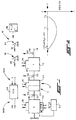
- Figure 1 is a schematic illustration of an automated mechanical transmission system of the type particularly well suited to be controlled by the method/apparatus of the present invention.
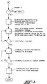
- FIG. 3 is a schematic illustration, in flow chart format, of the control system/method of the present invention.
- An engine brake 50 is provided for selectively retarding the rotational speed of engine 14 and a manually operated engine brake operator 52 is provided, usually in the vehicle cab, allowing the operator to selectively apply the engine brake.
- engine 14 is electronically controlled and is equipped to provide information on and to accept command signals from a data base conforming with a known protocol such as SAE J1939.
Landscapes
- Engineering & Computer Science (AREA)
- Chemical & Material Sciences (AREA)
- Combustion & Propulsion (AREA)
- Mechanical Engineering (AREA)
- General Engineering & Computer Science (AREA)
- Transportation (AREA)
- Control Of Transmission Device (AREA)
- Control Of Vehicle Engines Or Engines For Specific Uses (AREA)
- Control Of Driving Devices And Active Controlling Of Vehicle (AREA)
- Regulating Braking Force (AREA)
- Valve Device For Special Equipments (AREA)
Claims (10)
- Procédé de commande pour le changement de vitesse en haut sur un système de transmission mécanique automatique (10) sur des véhicules, comprenant un moteur contrôlé par une commande des gaz (14) ayant une plage des régimes d'environ 600 tours/min. à 2200 tours/min., une boîte de vitesses mécanique (12) possédant une pluralité de combinaisons de rapports d'engrenage pouvant être engrenées de manière sélective entre un arbre de transmission primaire (26) et un arbre de transmission principal (18), un accouplement à friction principal (16) pouvant être engrené et désengrené de manière sélective intercalé par entraînement entre ledit moteur et ladite transmission, une unité de traitement de l'information (54) possédant un moyen pour recevoir une pluralité de signaux d'entrée, notamment un signal d'entrée (ES) indiquant la vitesse de rotation dudit moteur et un signal d'entrée (OS) indiquant la vitesse de rotation dudit arbre principal et un moyen de traitement desdits signaux d'entrée conformément à des règles logiques prédéterminées pour générer des signaux de sortie de commande (54B) par lesquels ledit système de transmission est actionné conformément auxdites règles logiques, un frein moteur (50) pouvant être actionné de manière sélective pour fournir un couple de ralentissement variable de manière sélective à la rotation dudit moteur et des actionneurs répondant auxdits signaux de sortie de commande, notamment un actionneur d'alimentation (38) pour la commande de la quantité de carburant fourni audit moteur, un actionneur d'accouplement (42) pour engrener et désengrener de manière sélective ledit couplage, un opérateur de transmission (46) pour engrener et désengrener de manière sélective des rapports d'engrenage sélectionnés dans ladite transmission et un actionneur de frein moteur pour l'actionnement sélectif dudit frein moteur et un actionneur manuel (52) pour l'actionnement manuel dudit frein moteur, ledit procédé de commande comportantl'initiation d'un changement de vitesse en haut depuis un rapport d'engrenage (GRC) engrené généralement à un rapport d'engrenage cible (GRT), amenant ledit rapport d'engrenage généralement engrené à être désengrené et amenant ledit accouplement à friction principal à être engrené, ledit procédé étant caractérisé par :le fait d'amener automatiquement ledit frein moteur à être actionné avec un couple de ralentissement initial minimum et d'amener ensuite ledit frein moteur à être actionné avec un couple de ralentissement croissant jusqu'à ce qu'une valeur de couple de ralentissement maximum soit atteinte ;le fait de détecter que la vitesse du moteur excède le produit de la vitesse de l'arbre principal multipliée par le rapport arithmétique dudit rapport d'engrenage cible de moins d'une valeur de référence égale à environ 100 tours/min. (
 le fait de détecter que la vitesse du moteur excède ledit produit de la vitesse de l'arbre principal multipliée par le rapport arithmétique dudit rapport d'engrenage cible de moins d'une deuxième valeur de référence égale à environ 40 tours/min. (
- Procédé selon la revendication 1, dans lequel ledit frein moteur est un frein motocompresseur.
- Procédé selon la revendication 2, dans lequel ledit frein motocompresseur est un frein motocompresseur actionné hydrauliquement et où le couple de ralentissement appliqué par ledit frein motocompresseur est proportionnel à la pression hydraulique appliquée à celui-ci.
- Procédé selon la revendication 2, dans lequel ladite unité de commande est efficace pour la commande du couple de ralentissement appliqué audit moteur par ledit frein motocompresseur au moyen d'une pression hydraulique pulsée appliquée de manière sélective audit actionneur du frein motocompresseur.
- Procédé de commande selon la revendication 1, dans lequel ledit moteur Diesel comprend une pluralité de lignes de cylindres et où ledit frein moteur est un frein motocompresseur efficace pour fonctionner sur une ou plusieurs lignes desdits cylindres sélectionnés.
- Procédé de commande pour le changement de vitesse en haut sur un système de transmission mécanique automatique (10) sur des véhicules, comprenant un moteur controlé par une commande des gaz (14) ayant une plage des régimes d'environ 600 tours/min. à 2200 tours/min., une boîte de vitesses mécanique (12) comportant une pluralité de combinaisons de rapports d'engrenage pouvant être engrenées de manière sélective entre un arbre de transmission primaire (26) et un arbre de transmission principal (18), un accouplement à friction principal (16) pouvant être engrené et désengrené de manière sélective intercalé par entraînement entre ledit moteur et ladite transmission, une unité de traitement de l'information (54) possédant un moyen pour recevoir une pluralité de signaux d'entrée, notamment un signal d'entrée (ES) indiquant la vitesse de rotation dudit moteur et un signal d'entrée (OS) indiquant la vitesse de rotation dudit arbre principal et un moyen de traitement desdits signaux d'entrée conformément à des règles logiques prédéterminées pour générer des signaux de sortie de commande (54B) par lesquels ledit système de transmission est actionné conformément auxdites règles logiques, un frein moteur (50) pouvant être actionné de manière sélective pour fournir un couple de ralentissement variable de manière sélective à la rotation dudit moteur et des actionneurs répondant auxdits signaux de sortie de commande, notamment un actionneur d'alimentation (38) pour la commande de la quantité de carburant fourni audit moteur, un actionneur d'accouplement (42) pour engrener et désengrener de manière sélective ledit couplage, un opérateur de transmission (46) pour engrener et désengrener des rapports d'engrenage sélectionnés dans ladite transmission et un actionneur de frein moteur pour l'actionnement sélectif dudit frein moteur et un actionneur manuel (52) pour l'actionnement manuel dudit frein moteur, ledit procédé de commande comportantun moyen efficace pour l'initiation d'un changement de vitesse en haut depuis un rapport d'engrenage (GRC) engrené généralement à un rapport d'engrenage cible (GRT), pour amener ledit rapport d'engrenage généralement engrené à être désengrené et amenant ledit accouplement à friction principal à être engrené, ledit procédé étant caractérisé par :un moyen pour amener automatiquement ledit frein moteur à être actionné avec un couple de ralentissement initial minimum et d'amener ensuite ledit frein moteur à être actionné avec un couple de ralentissement croissant jusqu'à ce qu'une valeur de couple de ralentissement maximum soit atteinte ;un moyen pour détecter que la vitesse du moteur excède le produit de la vitesse de l'arbre principal multipliée par le rapport arithmétique dudit rapport d'engrenage cible de moins de la première valeur de référence égale à environ 100 tours/min. (
 un moyen pour détecter que la vitesse du moteur excède ledit produit de la vitesse de l'arbre principal multipliée par le rapport arithmétique dudit rapport d'engrenage cible de moins de la deuxième valeur de référence égale à environ 40 tours/min. (

- Système selon la revendication 6, dans lequel ledit frein moteur est un frein motocompresseur.
- Système selon la revendication 7, dans lequel ledit frein motocompresseur est un frein motocompresseur actionné hydrauliquement et où le couple de ralentissement appliqué par ledit frein motocompresseur est proportionnel à la pression hydraulique appliquée à celui-ci.
- Système selon la revendication 7, dans lequel l'unité de commande est efficace pour la commande du couple de ralentissement appliqué audit moteur par le frein motocompresseur par une pression hydraulique pulsée appliquée sélectivement audit actionneur de frein motocompresseur.
- Système de contrôle selon la revendication 6, dans lequel ledit moteur Diesel comprend une pluralité de lignes de cylindres et où ledit frein moteur est un frein motocompresseur efficace pour fonctionner sur une ou plusieurs lignes de cylindres sélectionnées.
Applications Claiming Priority (2)
| Application Number | Priority Date | Filing Date | Title |
|---|---|---|---|
| US08/103,947 US5409432A (en) | 1993-08-10 | 1993-08-10 | Control system/method for engine brake assisted shifting |
| US103947 | 1998-06-24 |
Publications (2)
| Publication Number | Publication Date |
|---|---|
| EP0638455A1 EP0638455A1 (fr) | 1995-02-15 |
| EP0638455B1 true EP0638455B1 (fr) | 1997-03-19 |
Family
ID=22297850
Family Applications (1)
| Application Number | Title | Priority Date | Filing Date |
|---|---|---|---|
| EP94305869A Expired - Lifetime EP0638455B1 (fr) | 1993-08-10 | 1994-08-08 | Dispositif/méthode de commande pour changement de vitesse assisté par les freins du moteur |
Country Status (5)
| Country | Link |
|---|---|
| US (1) | US5409432A (fr) |
| EP (1) | EP0638455B1 (fr) |
| AT (1) | ATE150390T1 (fr) |
| CA (1) | CA2129815C (fr) |
| DE (1) | DE69402134T2 (fr) |
Families Citing this family (53)
| Publication number | Priority date | Publication date | Assignee | Title |
|---|---|---|---|---|
| US5393276A (en) * | 1993-10-12 | 1995-02-28 | Cummins Electronics Company, Inc. | Method and apparatus for control of engine compression brakes before, during and after an electronically controlled gear shift |
| GB9411494D0 (en) * | 1994-06-08 | 1994-07-27 | Eaton Corp | System and method for decreasing ratio changing time in electronically enhanced powertrain systems |
| GB9412809D0 (en) * | 1994-06-25 | 1994-08-17 | Eaton Corp | Splitter section engagement control |
| US5571059A (en) * | 1995-07-27 | 1996-11-05 | Rockwell International Corporation | Operator input system for gear shift assist mechanism |
| US5679093A (en) * | 1995-07-27 | 1997-10-21 | Rockwell International Corporation | Engine speed retardation on transmission upshift |
| US5797110A (en) * | 1995-11-17 | 1998-08-18 | Eaton Corporation | Engine torque control |
| DE69622680T2 (de) * | 1996-01-12 | 2003-04-17 | Eaton Corp., Cleveland | Schaltsteuersystem/Verfahren für ein Fahrzeug,versehen mit einem Antriebsstrang-Retarder |
| US5678453A (en) * | 1996-02-01 | 1997-10-21 | Eaton Corporation | Start ratio selection for vehicular automated transmissions |
| US5679096A (en) * | 1996-04-08 | 1997-10-21 | Eaton Corporation | Torque control for powertrain and change-gear transmission utilized in same |
| US5682790A (en) * | 1996-04-30 | 1997-11-04 | Eaton Corporation | Synchronizing and gear engagement sensing logic for automated mechanical transmission system |
| GB9617956D0 (en) * | 1996-08-28 | 1996-10-09 | Eaton Corp | Downshift control method/system for vehicular automated mechanical transmission |
| DE19653231A1 (de) * | 1996-12-20 | 1998-06-25 | Bosch Gmbh Robert | Verfahren und Vorrichtung zur Beeinflussung des Getriebeeingangsmomentes |
| US5876302A (en) * | 1997-01-22 | 1999-03-02 | Meritor Heavy Vehicle Systems, Llc | Engine control with higher torque at direct drive transmission ratios |
| US5974354A (en) * | 1997-02-05 | 1999-10-26 | Eaton Corporation | Engagement of gear ratio confirmation |
| US5910069A (en) | 1997-12-22 | 1999-06-08 | Eaton Corporation | Transmission system control system/method including adaptive control for engine deceleration device |
| US6017291A (en) * | 1998-03-16 | 2000-01-25 | Eaton Corporation | Control system/method for input shaft retarder-assisted upshifts |
| US5989155A (en) * | 1998-04-01 | 1999-11-23 | Eaton Corporation | Engine fuel control for completing shifts in controller-assisted, manually shifted transmission |
| US5921883A (en) * | 1998-05-18 | 1999-07-13 | Cummins Engine Company, Inc. | System for managing engine retarding torque during coast mode operation |
| US6285941B1 (en) | 1998-08-31 | 2001-09-04 | Eaton Corporation | Method/system for controlling shifting in an automated mechanical transmission system |
| US6157886A (en) * | 1998-08-31 | 2000-12-05 | Eaton Corporation | Method/system for controlling upshifting in an automated mechanical transmission system |
| US6233512B1 (en) | 1998-09-08 | 2001-05-15 | Eaton Corporation | Method/system for controlling upshifting in an automated mechanical transmission system |
| US6223592B1 (en) * | 1998-11-13 | 2001-05-01 | Eaton Corporation | Independent control of transmission-side and engine-side retarding devices during ratio changes |
| GB9828452D0 (en) | 1998-12-24 | 1999-02-17 | Eaton Corp | Automated transmission downshift control |
| EP1013497B1 (fr) | 1998-12-24 | 2006-05-10 | Eaton Corporation | Contrôle des phases de rétrogradage dans une transmission automatique |
| US6113516A (en) * | 1999-01-14 | 2000-09-05 | Eaton Corporation | Adaptive automated transmission upshift control |
| US6325743B1 (en) | 1999-01-14 | 2001-12-04 | Eaton Corporation | Automated transmission upshift control |
| US6149545A (en) * | 1999-01-14 | 2000-11-21 | Eaton Corporation | Automated transmission upshift control |
| US6249733B1 (en) * | 1999-06-02 | 2001-06-19 | Caterpillar Inc. | Automatic engine retarder and transmission control in off highway earth moving equipment |
| US6126569A (en) * | 1999-07-19 | 2000-10-03 | Eaton Corporation | Starting and driveline shock protection control method and system |
| US6178366B1 (en) | 1999-07-19 | 2001-01-23 | Eaton Corporation | Method/system for initiating automatic upshifting in an automated mechanical transmission system |
| US6409629B1 (en) | 2000-05-17 | 2002-06-25 | Eaton Corporation | Automated transmission upshift control with upshift brake thermal protection |
| US6568256B1 (en) * | 2000-08-10 | 2003-05-27 | Ford Global Technologies, Llc. | System and method for controlling an automatic four-wheel drive transfer case which prevents excessive slippage |
| US6491603B1 (en) | 2000-09-12 | 2002-12-10 | Eaton Corporation | Automated transmission shift control |
| US6470851B1 (en) * | 2000-10-30 | 2002-10-29 | Caterpillar Inc | Method and apparatus of controlling the actuation of a compression brake |
| US6502476B2 (en) * | 2000-12-13 | 2003-01-07 | Eaton Corporation | Transmission system utilizing centrifugal clutch |
| US7108117B2 (en) * | 2000-12-13 | 2006-09-19 | Eaton Corporation | Centrifugal clutch |
| US6561949B2 (en) * | 2001-02-14 | 2003-05-13 | Ford Global Technologies, Llc. | Coupling assembly and a method for accelerating a vehicle and operating a transmission utilizing the coupling assembly |
| US6641504B2 (en) | 2001-03-21 | 2003-11-04 | Eaton Corporation | Method and system for establishing an engine speed target for use by a centrifugal clutch control system to launch a vehicle |
| US6539820B2 (en) | 2001-03-21 | 2003-04-01 | Eaton Corporation | Method and system for transmission utilizing centrifugal clutch to overcome transmission tooth-butt |
| US6461273B1 (en) | 2001-06-01 | 2002-10-08 | Eaton Corporation | Automated transmission upshift brake control |
| SE522166C2 (sv) * | 2002-05-17 | 2004-01-20 | Volvo Lastvagnar Ab | Förfarande för uppväxling vid motorfordon samt drivaggregat vid motorfordon |
| US7077024B2 (en) * | 2002-05-17 | 2006-07-18 | Volvo Lastvagnar Ab | Procedure for upshifting gear in a motor vehicle and a power plant unit for a motor vehicle |
| GB2389878A (en) * | 2002-06-18 | 2003-12-24 | Eaton Corp | Method of detecting false neutral in a transmission system |
| US6859710B2 (en) | 2002-11-25 | 2005-02-22 | Eaton Corporation | Automated centrifugal clutch system with open-loop throttle control |
| DE102004027597A1 (de) * | 2004-06-05 | 2005-12-22 | Zf Friedrichshafen Ag | Verfahren zur Steuerung eines automatisierten Schaltgetriebes |
| US7480555B2 (en) * | 2004-12-16 | 2009-01-20 | Eaton Corporation | Method for controlling centrifugal clutch engagement using engine torque requests |
| DE102007060822A1 (de) | 2007-12-18 | 2009-06-25 | Daimler Ag | Verfahren zum Steuern einer Motorbremseinrichtung einer Brennkraftmaschine und Brennkraftmaschine für ein Kraftfahrzeug |
| US7926464B2 (en) * | 2008-02-29 | 2011-04-19 | Caterpillar Inc. | Power source braking system to prevent engine stalls |
| SE540139C2 (en) * | 2016-07-11 | 2018-04-10 | Scania Cv Ab | Method of changing gear ratio in a gearbox of a vehicle |
| DE102017004818A1 (de) | 2017-05-18 | 2018-11-22 | Man Truck & Bus Ag | Verfahren zur Hochschaltunterstützung und Vorrichtung hierzu |
| US11760211B2 (en) * | 2019-09-12 | 2023-09-19 | Ford Global Technologies, Llc | System and method for changing gear ranges of an electric vehicle |
| CN113819234A (zh) * | 2021-08-18 | 2021-12-21 | 潍柴动力股份有限公司 | 一种换挡辅助控制方法、车辆 |
| CN116591831A (zh) * | 2023-05-18 | 2023-08-15 | 东风商用车有限公司 | 发动机制动升档调速优化系统及方法 |
Citations (1)
| Publication number | Priority date | Publication date | Assignee | Title |
|---|---|---|---|---|
| US4787044A (en) * | 1984-07-17 | 1988-11-22 | Nippondenso Co., Ltd. | Apparatus and method for controlling rotational speed of internal combustion engine for vehicles |
Family Cites Families (18)
| Publication number | Priority date | Publication date | Assignee | Title |
|---|---|---|---|---|
| JPS5828414B2 (ja) * | 1975-06-11 | 1983-06-15 | アイシンセイキ カブシキガイシヤ | エキゾ−ストブレ−キセイギヨソウチ |
| US4905544A (en) * | 1975-09-25 | 1990-03-06 | Ganoung David P | Powertrain control apparatus for improving fuel economy |
| US4361060A (en) * | 1978-01-24 | 1982-11-30 | Smyth Robert Ralston | Mechanical automatic transmission |
| GB8418749D0 (en) * | 1984-07-23 | 1984-08-30 | Eaton Ltd | Semi-automatic transmission control |
| US4595986A (en) * | 1984-10-09 | 1986-06-17 | Eaton Corporation | Method for control of automatic mechanical transmission system utilizing a microprocessor based electronic controller |
| DE3674768D1 (de) * | 1985-07-26 | 1990-11-08 | Fujitsu Ltd | Umsteuervorrichtung zum schnellen umschalten von vorwaerts- oder rueckwaertsgang bei mit automatischem getriebe ausgestattetem fahrzeug. |
| JPH0784149B2 (ja) * | 1985-09-30 | 1995-09-13 | アイシン精機株式会社 | 排気ブレ−キ付車両用自動変速機の制御方法 |
| US5050427A (en) * | 1986-04-07 | 1991-09-24 | Eaton Corporation | Method for controlling AMT system including speed sensor signal fault detection and tolerance |
| US4722248A (en) * | 1986-04-11 | 1988-02-02 | Eaton Corporation | Transmission shift control system |
| EP0270708B1 (fr) * | 1986-12-05 | 1990-08-29 | Eaton Corporation | Commande et procédé de commande d'un système de transmission automatique mécanique comportant un frein moteur à compression actionné à main |
| JPH01275938A (ja) * | 1988-04-26 | 1989-11-06 | Honda Motor Co Ltd | 自動変速機の変速制御方法 |
| US5097725A (en) * | 1988-07-25 | 1992-03-24 | Mazda Motor Corporation | Shift control system for automatic transmissions |
| US4945484A (en) * | 1988-10-13 | 1990-07-31 | Eaton Corporation | Method and control system for controlling AMT system including detection of erroneous gear neutral indication |
| GB8906918D0 (en) * | 1989-03-28 | 1989-05-10 | Eaton Corp | Method for upshifting a compound semi-blocked splitter type automatic mechanical transmission |
| JP2961275B2 (ja) * | 1989-03-30 | 1999-10-12 | アイシン精機株式会社 | 自動変速機の油圧制御装置 |
| DE3937302A1 (de) * | 1989-11-09 | 1991-05-16 | Man Nutzfahrzeuge Ag | Verfahren zum schalten eines unsynchronisierten (klauen-) schaltgetriebes und, gegebenenfalls automatischen, betaetigen der zugehoerigen kupplung |
| US5235877A (en) * | 1991-02-28 | 1993-08-17 | Toyota Jidosha Kabushiki Kaisha | Shift control apparatus for automatic transmission |
| JP2616603B2 (ja) * | 1991-05-23 | 1997-06-04 | 日産自動車株式会社 | 自動変速機の変速制御装置 |
-
1993
- 1993-08-10 US US08/103,947 patent/US5409432A/en not_active Expired - Fee Related
-
1994
- 1994-08-08 DE DE69402134T patent/DE69402134T2/de not_active Expired - Fee Related
- 1994-08-08 EP EP94305869A patent/EP0638455B1/fr not_active Expired - Lifetime
- 1994-08-08 AT AT94305869T patent/ATE150390T1/de not_active IP Right Cessation
- 1994-08-09 CA CA002129815A patent/CA2129815C/fr not_active Expired - Fee Related
Patent Citations (1)
| Publication number | Priority date | Publication date | Assignee | Title |
|---|---|---|---|---|
| US4787044A (en) * | 1984-07-17 | 1988-11-22 | Nippondenso Co., Ltd. | Apparatus and method for controlling rotational speed of internal combustion engine for vehicles |
Also Published As
| Publication number | Publication date |
|---|---|
| DE69402134D1 (de) | 1997-04-24 |
| US5409432A (en) | 1995-04-25 |
| EP0638455A1 (fr) | 1995-02-15 |
| CA2129815A1 (fr) | 1995-02-11 |
| CA2129815C (fr) | 1999-10-19 |
| ATE150390T1 (de) | 1997-04-15 |
| DE69402134T2 (de) | 1997-06-26 |
Similar Documents
| Publication | Publication Date | Title |
|---|---|---|
| CA2129815C (fr) | Systeme/methode de commande du changement de vitesse assiste(e) par le freinage du moteur | |
| US5910069A (en) | Transmission system control system/method including adaptive control for engine deceleration device | |
| US5634867A (en) | Main clutch reengagement control for a double clutch downshift | |
| EP0837786B1 (fr) | Reduction du regime moteur lors du passage a un rapport superieur | |
| US5441462A (en) | Clutch disengage logic | |
| EP1013973B1 (fr) | Contrôle indépendant d'un ralentisseur côte boîte de vitesses et côte moteur pendant le changement de vitesses | |
| EP0352551B1 (fr) | Logique pour passer à des rapports supérieurs | |
| EP0244096B1 (fr) | Procédé de commande d'une transmission mécanique automatique, y compris la commande pour l'embrayage et le carburant au départ arrêté | |
| EP0686789B1 (fr) | Procédé pour réduire la durée de changement de vitesse dans des groupes motopropulseurs | |
| US5435795A (en) | Vehicle drivetrain control including CVT | |
| CZ379792A3 (en) | Process and apparatus for determining contact point of friction clutch | |
| US5529548A (en) | Vehicle launch engine fuel control | |
| JPH0811511B2 (ja) | 車両用自動機械式変速システムの制御方法及びその制御装置 | |
| CA2113873A1 (fr) | Avertissement d'anomalie dans le fonctionnement d'un engrenage | |
| JPH10504877A (ja) | 走行駆動装置 | |
| EP0378218B1 (fr) | Système de commande d'entraînement d'un véhicule à moteur | |
| US6471022B1 (en) | Method and device for actuating a motor vehicle clutch device | |
| EP0431538B1 (fr) | Opération manuelle superposée d'une transmission mécanique automatisée | |
| JPH11325224A (ja) | アップシフトの制御システムおよびその方法 | |
| EP0834681B1 (fr) | Appareil et méthode de commande de rétrogradage pour une transmission mécanique automatique pour véhicule | |
| JPS61184136A (ja) | 自動車用自動減速装置 |
Legal Events
| Date | Code | Title | Description |
|---|---|---|---|
| PUAI | Public reference made under article 153(3) epc to a published international application that has entered the european phase |
Free format text: ORIGINAL CODE: 0009012 |
|
| AK | Designated contracting states |
Kind code of ref document: A1 Designated state(s): AT DE FR GB IT SE |
|
| 17P | Request for examination filed |
Effective date: 19941223 |
|
| 17Q | First examination report despatched |
Effective date: 19951211 |
|
| GRAG | Despatch of communication of intention to grant |
Free format text: ORIGINAL CODE: EPIDOS AGRA |
|
| GRAH | Despatch of communication of intention to grant a patent |
Free format text: ORIGINAL CODE: EPIDOS IGRA |
|
| GRAH | Despatch of communication of intention to grant a patent |
Free format text: ORIGINAL CODE: EPIDOS IGRA |
|
| GRAA | (expected) grant |
Free format text: ORIGINAL CODE: 0009210 |
|
| ITF | It: translation for a ep patent filed | ||
| AK | Designated contracting states |
Kind code of ref document: B1 Designated state(s): AT DE FR GB IT SE |
|
| REF | Corresponds to: |
Ref document number: 150390 Country of ref document: AT Date of ref document: 19970415 Kind code of ref document: T |
|
| REF | Corresponds to: |
Ref document number: 69402134 Country of ref document: DE Date of ref document: 19970424 |
|
| ET | Fr: translation filed | ||
| PLBE | No opposition filed within time limit |
Free format text: ORIGINAL CODE: 0009261 |
|
| STAA | Information on the status of an ep patent application or granted ep patent |
Free format text: STATUS: NO OPPOSITION FILED WITHIN TIME LIMIT |
|
| 26N | No opposition filed | ||
| REG | Reference to a national code |
Ref country code: GB Ref legal event code: IF02 |
|
| PGFP | Annual fee paid to national office [announced via postgrant information from national office to epo] |
Ref country code: AT Payment date: 20050624 Year of fee payment: 12 |
|
| PGFP | Annual fee paid to national office [announced via postgrant information from national office to epo] |
Ref country code: GB Payment date: 20050707 Year of fee payment: 12 |
|
| PGFP | Annual fee paid to national office [announced via postgrant information from national office to epo] |
Ref country code: FR Payment date: 20050804 Year of fee payment: 12 |
|
| PGFP | Annual fee paid to national office [announced via postgrant information from national office to epo] |
Ref country code: SE Payment date: 20050805 Year of fee payment: 12 |
|
| PGFP | Annual fee paid to national office [announced via postgrant information from national office to epo] |
Ref country code: DE Payment date: 20050831 Year of fee payment: 12 |
|
| PG25 | Lapsed in a contracting state [announced via postgrant information from national office to epo] |
Ref country code: AT Free format text: LAPSE BECAUSE OF NON-PAYMENT OF DUE FEES Effective date: 20060808 |
|
| PG25 | Lapsed in a contracting state [announced via postgrant information from national office to epo] |
Ref country code: SE Free format text: LAPSE BECAUSE OF NON-PAYMENT OF DUE FEES Effective date: 20060809 |
|
| PGFP | Annual fee paid to national office [announced via postgrant information from national office to epo] |
Ref country code: IT Payment date: 20060831 Year of fee payment: 13 |
|
| PG25 | Lapsed in a contracting state [announced via postgrant information from national office to epo] |
Ref country code: DE Free format text: LAPSE BECAUSE OF NON-PAYMENT OF DUE FEES Effective date: 20070301 |
|
| EUG | Se: european patent has lapsed | ||
| GBPC | Gb: european patent ceased through non-payment of renewal fee |
Effective date: 20060808 |
|
| REG | Reference to a national code |
Ref country code: FR Ref legal event code: ST Effective date: 20070430 |
|
| PG25 | Lapsed in a contracting state [announced via postgrant information from national office to epo] |
Ref country code: GB Free format text: LAPSE BECAUSE OF NON-PAYMENT OF DUE FEES Effective date: 20060808 |
|
| PG25 | Lapsed in a contracting state [announced via postgrant information from national office to epo] |
Ref country code: FR Free format text: LAPSE BECAUSE OF NON-PAYMENT OF DUE FEES Effective date: 20060831 |
|
| PG25 | Lapsed in a contracting state [announced via postgrant information from national office to epo] |
Ref country code: IT Free format text: LAPSE BECAUSE OF NON-PAYMENT OF DUE FEES Effective date: 20070808 |