EP0640769B1 - Automatisches Aufwärmverfahren in hydraulischen Systemen - Google Patents
Automatisches Aufwärmverfahren in hydraulischen Systemen Download PDFInfo
- Publication number
- EP0640769B1 EP0640769B1 EP94106610A EP94106610A EP0640769B1 EP 0640769 B1 EP0640769 B1 EP 0640769B1 EP 94106610 A EP94106610 A EP 94106610A EP 94106610 A EP94106610 A EP 94106610A EP 0640769 B1 EP0640769 B1 EP 0640769B1
- Authority
- EP
- European Patent Office
- Prior art keywords
- engine
- temperature
- hydraulic
- warming
- rotation speed
- Prior art date
- Legal status (The legal status is an assumption and is not a legal conclusion. Google has not performed a legal analysis and makes no representation as to the accuracy of the status listed.)
- Expired - Lifetime
Links
- 238000000034 method Methods 0.000 title claims description 18
- 239000000314 lubricant Substances 0.000 claims description 6
- 239000000498 cooling water Substances 0.000 claims description 5
- 238000010792 warming Methods 0.000 claims description 5
- 230000032683 aging Effects 0.000 description 2
- 238000010586 diagram Methods 0.000 description 2
- 230000007613 environmental effect Effects 0.000 description 2
- 238000004519 manufacturing process Methods 0.000 description 2
- 239000000446 fuel Substances 0.000 description 1
Images

Classifications
-
- F—MECHANICAL ENGINEERING; LIGHTING; HEATING; WEAPONS; BLASTING
- F02—COMBUSTION ENGINES; HOT-GAS OR COMBUSTION-PRODUCT ENGINE PLANTS
- F02N—STARTING OF COMBUSTION ENGINES; STARTING AIDS FOR SUCH ENGINES, NOT OTHERWISE PROVIDED FOR
- F02N19/00—Starting aids for combustion engines, not otherwise provided for
- F02N19/02—Aiding engine start by thermal means, e.g. using lighted wicks
-
- F—MECHANICAL ENGINEERING; LIGHTING; HEATING; WEAPONS; BLASTING
- F16—ENGINEERING ELEMENTS AND UNITS; GENERAL MEASURES FOR PRODUCING AND MAINTAINING EFFECTIVE FUNCTIONING OF MACHINES OR INSTALLATIONS; THERMAL INSULATION IN GENERAL
- F16H—GEARING
- F16H57/00—General details of gearing
- F16H57/04—Features relating to lubrication or cooling or heating
-
- F—MECHANICAL ENGINEERING; LIGHTING; HEATING; WEAPONS; BLASTING
- F02—COMBUSTION ENGINES; HOT-GAS OR COMBUSTION-PRODUCT ENGINE PLANTS
- F02D—CONTROLLING COMBUSTION ENGINES
- F02D29/00—Controlling engines, such controlling being peculiar to the devices driven thereby, the devices being other than parts or accessories essential to engine operation, e.g. controlling of engines by signals external thereto
- F02D29/04—Controlling engines, such controlling being peculiar to the devices driven thereby, the devices being other than parts or accessories essential to engine operation, e.g. controlling of engines by signals external thereto peculiar to engines driving pumps
-
- F—MECHANICAL ENGINEERING; LIGHTING; HEATING; WEAPONS; BLASTING
- F02—COMBUSTION ENGINES; HOT-GAS OR COMBUSTION-PRODUCT ENGINE PLANTS
- F02D—CONTROLLING COMBUSTION ENGINES
- F02D41/00—Electrical control of supply of combustible mixture or its constituents
- F02D41/02—Circuit arrangements for generating control signals
- F02D41/04—Introducing corrections for particular operating conditions
- F02D41/06—Introducing corrections for particular operating conditions for engine starting or warming up
Definitions
- the present invention relates to an automatic warming-up method thereof in hydraulic system, and more particularly, to an automatic warming-up method thereof applied in various hydraulic systems which are equipped with an engine and a hydraulic pump driven by the engine, and controlled by a microcomputer.
- the conventional hydraulic system is provided with an engine and a hydraulic pump driven by the engine, and operated by supplying a discharge oil of the hydraulic pump to one or a plurality of hydraulic actuators.
- these methods include the method in which the warming-up is performed until the operation can be done with 100 % load by increasing manually the rotation speed of the engine or controlling the discharge pressure and the discharge oil amount of the hydraulic pump, and the method in which an instruction is given by a controller so that the engine is warmed-up until the appropriate number of rotation is reached and, at the same time, the discharge pressure and the discharge oil amount of the hydraulic pump are adjusted based on the allowable output of the engine which is determined by detecting the rack position of a fuel supply pump through a sensor.
- the manual warming-up method has problem that it is not only inaccurate but toilsome, and the automatic warming-up method has problems of the difficult initial adjustment of the sensor for detecting the rack position, an aging due to the use for a long period, and a weak environmental durability since it is installed in the inside of the engine.
- WO 89/05396 Another example of the conventional warming up device and method in hydraulic system is disclosed in WO 89/05396.
- the engine controller gives out an order for warming up the engine at a predetermined rotational speed in accordance with the information from the temperature sensors.
- the engine controller ascertains that the level of an output from the engine becomes higher than a required level, on the basis of the information from the rack position sensor, excessive output from the engine is outputted in the form of an engine load signal to a hydraulic controller.
- the discharge rate and discharge pressure of a hydraulic pump are set by the hydraulic controller to the levels which match the excessive output from the engine.
- this system also depends on the rack position sensor, and inevitably has the problems of the difficult initial adjustment, an aging due to the use for a long period, and a weak environmental durability.
- Fig. 1 illustrates an automatic warming-up apparatus.
- a hydraulic system employing the automatic warming-up apparatus of this embodiment has an engine 2, a hydraulic pump 5 driven by the engine 2, a hydraulic valve 6 for supplying selectively the discharged oil from a hydraulic pump 5 to a corresponding hydraulic actuator 11, an engine controller 1 for controlling the engine 2 by the operation amount of a throttle lever 3 and the speed signal received from a rotation speed sensor 14 of the engine 2, and a pump controller 4 for controlling variably the discharge pressure, the discharge oil amount of the hydraulic pump 5 and the direction of the hydraulic valve 6 by the control signal received from the engine controller 1.
- Reference numeral 12 is an oil tank.
- the scope of the present invention does not limit to the hydraulic system described in the above which illustrates the only one embodiment of the present invention.
- the automatic warming-up apparatus of the present invention can be applied for various types of hydraulic systems, for example, the engine controller and the pump controller can be consisted of a single controller containing a microcomputer.
- the automatic warming-up apparatus of this embodiment has a first temperature sensor 10 for detecting the temperature of lubricant oil of the engine 2, a second temperature sensor 15 for detecting the temperature of cooling water of the engine 2, a third temperature sensor 13 for detecting the temperature of pressurized oil in the oil tank 12, and an input/output unit 8 for sending to the engine controller 1 the temperature signals(i.e. the temperature signals of lubricant oil, cooling water, and pressurized oil) received from the sensors 10, 15 and 13, respectively.
- a display unit(9: monitor) is connected to the input/output unit 8 so that the temperature signals are displayed in distinguished forms.
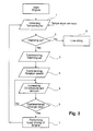
- the lubricant oil temperature signal, cooling water temperature and pressurized oil temperature signal detected from the first temperature sensor 10, the second temperature sensor 15 and the third temperature sensor 13 respectively, are sent to the engine controller 1 through the input/output unit 8(1st step).
- the engine controller 1 determines whether or not the warming-up is performed by comparing the temperature signals from the temperature sensors 10, 13 and 15 with predetermined values(2nd step).
- the 8th step is immediately proceeded to carry out low-idling operation.
- the pump controller 4 according to the instruction from the engine controller, slowly increases the discharge oil amount and pressure of the hydraulic pump 5 and hydraulic valve 6 until the change rate in the rotation speed of the engine 2 reaches the predetermined values(5th step). At this time, the change rate in the rotation speed of the engine 2 is determined by the maximum load capacity of the engine 2 required by the hydraulic actuator 11.
- the 6th step determines whether or not the discharge oil amount and pressure increased in the 5th step have reached the predetermined change rate in the rotation speed of the engine 2. If the increased discharge oil amount and pressure have not reached the predetermined value, the process goes back to the 5th step and increases further the discharge oil amount and pressure.
- the automatic warming-up apparatus of the present invention is applied in the hydraulic system with a stable performance, a low manufacturing cost, and improved reliability.
Landscapes
- Engineering & Computer Science (AREA)
- General Engineering & Computer Science (AREA)
- Mechanical Engineering (AREA)
- Chemical & Material Sciences (AREA)
- Combustion & Propulsion (AREA)
- Fluid-Pressure Circuits (AREA)
- Control Of Vehicle Engines Or Engines For Specific Uses (AREA)
- General Details Of Gearings (AREA)
- Control Of Temperature (AREA)
- Combined Controls Of Internal Combustion Engines (AREA)
- Control Of Positive-Displacement Pumps (AREA)
Claims (1)
- Automatisches Aufwärmverfahren in einem hydraulischen System, umfassend einen Motor (2), eine hydraulische Pumpe (5), die von dem Motor (2) angetrieben wird, mindestens einen hydraulischen Betätiger (11), welcher durch eine Ölzuführung von der hydraulischen Pumpe (5) angetrieben wird, einen Regler (1), welcher die Rotationsgeschwindigkeit des Motors (2), die zugeführte Ölmenge und den Druck der hydraulischen Pumpe (5) regelt, einen ersten Temperatursensor (10), welcher die Temperatur eines Schmieröles des Motors (2) erfaßt, einen zweiten Temperatursensor (15), welcher eine Kühlwassertemperatur des Motors (2) erfaßt; einen dritten Temperatursensor (13), welcher die Temperatur eines Drucköles des hydraulischen Systems erfaßt, eine Eingangs-/Ausgangseinheit (8), welche dem Regler (1) die von den Sensoren empfangenen Temperatursignale übermittelt, gekennzeichnet durch folgende Verfahrensschritte:(1) Erfassung der Temperatur des Schmieröles des Motors durch den ersten Temperatursensor, der Temperatur des Kühlwassers des Motors durch den zweiten Temperatursensor und der Temperatur des Drucköles des hydraulischen Systems durch den dritten Temperatursensor; Übermittlung der erfaßten Temperatursignale über die Eingangs-/Ausgangseinrichtung zum Regler;(2) Bestimmung, ob eine Aufwärmung durchzuführen ist oder nicht, indem die Temperatursignale mit vorgegebenen Temperaturwerten verglichen werden;(3) Veranlassung der Aufwärmung, wenn die Temperaturen unterhalb der vorgegebenen Temperaturwerte liegen;(4) Übermittlung eines Steuersignales, um den Motor (2) mit einer vorbestimmten Rotationsgeschwindigkeit anzutreiben;(5) Relativ langsame Erhöhung der Menge der Ölzuführung und des Drukkes von der hydraulischen Pumpe, bis durch den Änderungswert der Rotationsgeschwindigkeit des Motors die vorbestimmte Rotationsgeschwindigkeit erreicht ist;(6) Regelung des Änderungswertes der Rotationsgeschwindigkeit des Motors damit diese einen vorbestimmten Wert hat, wenn die Temperatursignale unterhalb der vorbestimmten Temperaturwerte liegen; und(7) Weiterbetreiben der Funktion des Motors (2) durch Zurückgehen zum ersten Verfahrensschritt.
Applications Claiming Priority (2)
| Application Number | Priority Date | Filing Date | Title |
|---|---|---|---|
| KR9312149 | 1993-06-30 | ||
| KR1019930012149A KR100188882B1 (ko) | 1993-06-30 | 1993-06-30 | 내연기관 및 유압펌프의 자동예열시스템 |
Publications (2)
| Publication Number | Publication Date |
|---|---|
| EP0640769A1 EP0640769A1 (de) | 1995-03-01 |
| EP0640769B1 true EP0640769B1 (de) | 1998-10-14 |
Family
ID=19358387
Family Applications (1)
| Application Number | Title | Priority Date | Filing Date |
|---|---|---|---|
| EP94106610A Expired - Lifetime EP0640769B1 (de) | 1993-06-30 | 1994-04-27 | Automatisches Aufwärmverfahren in hydraulischen Systemen |
Country Status (5)
| Country | Link |
|---|---|
| US (1) | US5410878A (de) |
| EP (1) | EP0640769B1 (de) |
| JP (1) | JPH0726997A (de) |
| KR (1) | KR100188882B1 (de) |
| DE (1) | DE69413914T2 (de) |
Families Citing this family (23)
| Publication number | Priority date | Publication date | Assignee | Title |
|---|---|---|---|---|
| KR100490109B1 (ko) * | 1997-02-28 | 2005-07-18 | 볼보 컨스트럭션 이키프먼트 홀딩 스웨덴 에이비 | 건설기계엔진의자동예열제어방법 |
| US5971503A (en) * | 1998-02-03 | 1999-10-26 | Ford Global Technologies, Inc. | Hydraulic control unit with ambient temperature compensation during fluid pressure delivery |
| US6076637A (en) * | 1998-03-23 | 2000-06-20 | Tranergy Corporation | Top-of-rail lubrication rate control by the hydraulic pulse width modulation method |
| US6416141B1 (en) * | 1999-02-25 | 2002-07-09 | Kelsey-Hayes Company | Methods for improving braking performance in electronically-controlled hydraulic brake systems |
| US6397590B1 (en) | 2000-05-15 | 2002-06-04 | Hr Textron Inc. | Hydraulic warming system for use in low ambient temperature applications |
| JP3775245B2 (ja) * | 2001-06-11 | 2006-05-17 | コベルコ建機株式会社 | 建設機械のポンプ制御装置 |
| US6634172B2 (en) | 2002-02-26 | 2003-10-21 | Grove U.S. Llc | Thermal contraction control apparatus for hydraulic cylinders |
| US7234922B2 (en) * | 2002-05-09 | 2007-06-26 | Clarke Fire Protection Products, Inc. | Pump pressure limiting engine speed control and related engine and sprinkler system |
| JP4331208B2 (ja) * | 2004-09-27 | 2009-09-16 | 日立建機株式会社 | 作業車両の原動機制御装置 |
| JP4541211B2 (ja) * | 2005-03-31 | 2010-09-08 | ナブテスコ株式会社 | 建設機械の走行モータ制御装置 |
| DE602006021017D1 (de) * | 2005-03-31 | 2011-05-12 | Nabtesco Corp | Steuervorrichtung des Antriebsmotors einer Arbeitsmaschine |
| DE102006005712A1 (de) * | 2006-02-08 | 2007-08-16 | Robert Bosch Gmbh | Verfahren und Vorrichtung zur Überwachung wenigstens einer Glühkerzen eines Kraftfahrzeugs |
| JP4024820B2 (ja) * | 2006-08-01 | 2007-12-19 | 住友建機製造株式会社 | 建設機械の制御装置 |
| US20090129935A1 (en) * | 2007-11-21 | 2009-05-21 | Kunkler Kevin J | Pump suction pressure limiting speed control and related pump driver and sprinkler system |
| US8234860B2 (en) * | 2008-08-29 | 2012-08-07 | Caterpillar Inc. | Machine control system having hydraulic warmup procedure |
| US8096781B2 (en) * | 2008-09-24 | 2012-01-17 | Caterpillar Inc. | Hydraulic pump system with reduced cold start parasitic loss |
| WO2012170394A1 (en) | 2011-06-09 | 2012-12-13 | Clarke Fire Protection Products, Inc. | Cooling arrangements for fire suppression sprinkler system fire pumps |
| CN102767204B (zh) * | 2012-07-27 | 2015-02-18 | 中联重科股份有限公司渭南分公司 | 暖机控制设备、控制系统和控制方法及工程机械设备 |
| EP2873872A1 (de) * | 2013-09-18 | 2015-05-20 | Alfred Kärcher GmbH & Co. KG | Geräteträger mit verbesserter Steuerung der Hydraulikflüssigkeitsversorgung |
| US9803665B2 (en) * | 2014-03-18 | 2017-10-31 | Caterpillar Inc. | Machine control system having hydraulic warmup procedure |
| DE102015212727A1 (de) | 2015-07-08 | 2017-01-12 | Robert Bosch Gmbh | Hydrostatisches Getriebe, Fahrantrieb mit dem Getriebe und Verfahren zur Steuerung des Getriebes |
| KR20170084813A (ko) * | 2016-01-13 | 2017-07-21 | 두산인프라코어 주식회사 | 건설기계의 난기 운전 시스템 및 이를 이용한 건설기계의 제어 방법 |
| WO2019217961A1 (en) | 2018-05-11 | 2019-11-14 | Clark Equipment Company | Hydraulic drive control |
Family Cites Families (6)
| Publication number | Priority date | Publication date | Assignee | Title |
|---|---|---|---|---|
| GB2072890B (en) * | 1979-10-15 | 1983-08-10 | Hitachi Construction Machinery | Method of controlling internal combustion engine and hydraulic pump system |
| JPS6243327A (ja) * | 1985-08-19 | 1987-02-25 | Mazda Motor Corp | エンジンの暖機制御装置 |
| JPH01147128A (ja) * | 1987-12-03 | 1989-06-08 | Komatsu Ltd | 内燃機関および油圧ポンプの自動暖機システム |
| GB2251962B (en) * | 1990-11-13 | 1995-05-24 | Samsung Heavy Ind | System for automatically controlling an operation of a heavy construction |
| US5199326A (en) * | 1990-11-28 | 1993-04-06 | Toyota Jidosha Kabushiki Kaisha | Idle up of engine of automobile according to elevation of transmission oil temperature |
| JP3098859B2 (ja) * | 1992-06-10 | 2000-10-16 | 新キャタピラー三菱株式会社 | 可変容量型油圧ポンプと油圧ポンプ駆動エンジンの制御方法 |
-
1993
- 1993-06-30 KR KR1019930012149A patent/KR100188882B1/ko not_active Expired - Fee Related
-
1994
- 1994-04-27 EP EP94106610A patent/EP0640769B1/de not_active Expired - Lifetime
- 1994-04-27 DE DE69413914T patent/DE69413914T2/de not_active Expired - Fee Related
- 1994-04-28 US US08/234,226 patent/US5410878A/en not_active Expired - Fee Related
- 1994-04-28 JP JP6113558A patent/JPH0726997A/ja active Pending
Also Published As
| Publication number | Publication date |
|---|---|
| DE69413914T2 (de) | 1999-03-11 |
| EP0640769A1 (de) | 1995-03-01 |
| US5410878A (en) | 1995-05-02 |
| DE69413914D1 (de) | 1998-11-19 |
| KR100188882B1 (ko) | 1999-06-01 |
| JPH0726997A (ja) | 1995-01-27 |
| KR950001089A (ko) | 1995-01-03 |
Similar Documents
| Publication | Publication Date | Title |
|---|---|---|
| EP0640769B1 (de) | Automatisches Aufwärmverfahren in hydraulischen Systemen | |
| US5855532A (en) | Method and system for controlling automatic transmission | |
| EP0540758B1 (de) | Vorrichtung zur drehzahlregelung bei einer fahrzeugbrennkraftmaschine | |
| EP2113672B1 (de) | Anordnung zum Bedienen einer hydraulischen Vorrichtung | |
| US4883034A (en) | Engine idling speed control system | |
| US5987888A (en) | System and method for controlling a turbocharger | |
| US4748951A (en) | Apparatus for and method of controlling the idling of automobile engine | |
| JPH11507117A (ja) | 駆動ユニットの出力トルクの制御方法および装置 | |
| US4807497A (en) | System for integrally controlling automatic transmission and engine | |
| US4531490A (en) | Idling speed feedback control method having fail-safe function for abnormalities in functioning of crank angle position-detecting system of an internal combustion engine | |
| US5083480A (en) | Shift control system for automotive automatic power transmission with kick-down control according to prediction of demanded engine load | |
| US6619259B2 (en) | Electronically controlled throttle control system | |
| US4713987A (en) | Reduction ratio control for continuously variable transmission | |
| EP0791737A1 (de) | Vorrichtung zur steuerung der drehzahl eines motors einer hydraulischen baumaschine | |
| US5343392A (en) | Method of diagnosing power steering system | |
| US6145486A (en) | Apparatus for controlling fuel injection quantity at the time of starting diesel engine and method | |
| US6853891B2 (en) | Low speed shift strategy for marine engines | |
| KR20010023254A (ko) | 컨버터 분기 클러치의 적응방법 | |
| KR100579219B1 (ko) | 주행 상태에 따른 스모크 저감 방법 | |
| JPH1054269A (ja) | 限界負荷制御法 | |
| KR100279453B1 (ko) | 자동 변속기의 유압 제어 방법 | |
| KR100188768B1 (ko) | 자동 변속장치의 유체상태를 고려한 아이들 제어장치 및 그 방법 | |
| JPH0650419A (ja) | 自動変速機の油圧制御装置 | |
| JPH0243903B2 (de) | ||
| JPH04347052A (ja) | 自動変速機の変速異常検出装置 |
Legal Events
| Date | Code | Title | Description |
|---|---|---|---|
| PUAI | Public reference made under article 153(3) epc to a published international application that has entered the european phase |
Free format text: ORIGINAL CODE: 0009012 |
|
| AK | Designated contracting states |
Kind code of ref document: A1 Designated state(s): DE FR GB IT |
|
| 17P | Request for examination filed |
Effective date: 19950821 |
|
| 17Q | First examination report despatched |
Effective date: 19960612 |
|
| GRAG | Despatch of communication of intention to grant |
Free format text: ORIGINAL CODE: EPIDOS AGRA |
|
| GRAG | Despatch of communication of intention to grant |
Free format text: ORIGINAL CODE: EPIDOS AGRA |
|
| GRAH | Despatch of communication of intention to grant a patent |
Free format text: ORIGINAL CODE: EPIDOS IGRA |
|
| GRAH | Despatch of communication of intention to grant a patent |
Free format text: ORIGINAL CODE: EPIDOS IGRA |
|
| GRAA | (expected) grant |
Free format text: ORIGINAL CODE: 0009210 |
|
| AK | Designated contracting states |
Kind code of ref document: B1 Designated state(s): DE FR GB IT |
|
| ITPR | It: changes in ownership of a european patent |
Owner name: CESSIONE EPO;VOLVO COSTURCTION EQUI PMENT KOREA CO |
|
| REF | Corresponds to: |
Ref document number: 69413914 Country of ref document: DE Date of ref document: 19981119 |
|
| ET | Fr: translation filed | ||
| REG | Reference to a national code |
Ref country code: FR Ref legal event code: TP |
|
| RAP2 | Party data changed (patent owner data changed or rights of a patent transferred) |
Owner name: VOLVO CONSTRUCTION EQUIPMENT KOREA CO., LTD. |
|
| REG | Reference to a national code |
Ref country code: GB Ref legal event code: 732E |
|
| PLBE | No opposition filed within time limit |
Free format text: ORIGINAL CODE: 0009261 |
|
| STAA | Information on the status of an ep patent application or granted ep patent |
Free format text: STATUS: NO OPPOSITION FILED WITHIN TIME LIMIT |
|
| 26N | No opposition filed | ||
| PGFP | Annual fee paid to national office [announced via postgrant information from national office to epo] |
Ref country code: FR Payment date: 20010409 Year of fee payment: 8 |
|
| PGFP | Annual fee paid to national office [announced via postgrant information from national office to epo] |
Ref country code: DE Payment date: 20010423 Year of fee payment: 8 |
|
| PGFP | Annual fee paid to national office [announced via postgrant information from national office to epo] |
Ref country code: GB Payment date: 20010425 Year of fee payment: 8 |
|
| REG | Reference to a national code |
Ref country code: GB Ref legal event code: IF02 |
|
| PG25 | Lapsed in a contracting state [announced via postgrant information from national office to epo] |
Ref country code: GB Free format text: LAPSE BECAUSE OF NON-PAYMENT OF DUE FEES Effective date: 20020427 |
|
| PG25 | Lapsed in a contracting state [announced via postgrant information from national office to epo] |
Ref country code: DE Free format text: LAPSE BECAUSE OF NON-PAYMENT OF DUE FEES Effective date: 20021101 |
|
| GBPC | Gb: european patent ceased through non-payment of renewal fee |
Effective date: 20020427 |
|
| PG25 | Lapsed in a contracting state [announced via postgrant information from national office to epo] |
Ref country code: FR Free format text: LAPSE BECAUSE OF NON-PAYMENT OF DUE FEES Effective date: 20021231 |
|
| REG | Reference to a national code |
Ref country code: FR Ref legal event code: ST |
|
| PG25 | Lapsed in a contracting state [announced via postgrant information from national office to epo] |
Ref country code: IT Free format text: LAPSE BECAUSE OF NON-PAYMENT OF DUE FEES;WARNING: LAPSES OF ITALIAN PATENTS WITH EFFECTIVE DATE BEFORE 2007 MAY HAVE OCCURRED AT ANY TIME BEFORE 2007. THE CORRECT EFFECTIVE DATE MAY BE DIFFERENT FROM THE ONE RECORDED. Effective date: 20050427 |