EP0641876A1 - Optimisation du nettoyage - Google Patents
Optimisation du nettoyage Download PDFInfo
- Publication number
- EP0641876A1 EP0641876A1 EP94114935A EP94114935A EP0641876A1 EP 0641876 A1 EP0641876 A1 EP 0641876A1 EP 94114935 A EP94114935 A EP 94114935A EP 94114935 A EP94114935 A EP 94114935A EP 0641876 A1 EP0641876 A1 EP 0641876A1
- Authority
- EP
- European Patent Office
- Prior art keywords
- cleaning
- fiber
- signal
- bale
- coarse
- Prior art date
- Legal status (The legal status is an assumption and is not a legal conclusion. Google has not performed a legal analysis and makes no representation as to the accuracy of the status listed.)
- Granted
Links
Images

Classifications
-
- D—TEXTILES; PAPER
- D01—NATURAL OR MAN-MADE THREADS OR FIBRES; SPINNING
- D01G—PRELIMINARY TREATMENT OF FIBRES, e.g. FOR SPINNING
- D01G9/00—Opening or cleaning fibres, e.g. scutching cotton
-
- D—TEXTILES; PAPER
- D01—NATURAL OR MAN-MADE THREADS OR FIBRES; SPINNING
- D01G—PRELIMINARY TREATMENT OF FIBRES, e.g. FOR SPINNING
- D01G7/00—Breaking or opening fibre bales
Definitions
- the invention relates to a method for optimizing the processing of cotton in a spinning mill in terms of throughput, residual dirt content and fiber impairment of the processed product or. in the processed product.
- the task was therefore to find a solution for optimizing the degree of cleaning, taking into account the different demands made on the latter two variables by the corresponding spinning process.
- the opening of the fiber bales into fiber flakes should result in the smallest possible flock sizes
- the speed of the opening rollers and the intensity of these opening rollers in combination with knife or carding elements should be such that fiber impairments only occur to a tolerable extent.
- this object is now achieved in a fiber processing system with a bale opener, a coarse cleaner and a system controller, characterized in that both the bale opener and the coarse cleaner can be set as a function of the fiber material to be processed, and the control is arranged such that the Coarse cleaner is set depending on the fiber material currently supplied by the bale opener.
- a calculated degree of cleaning by means of sensors checked in the outlet area of the cleaning machines, or monitored during operation and possibly corrected automatically.
- the advantages achieved by the invention are essentially to be seen in the fact that the cleaning intensity can be adapted to the requirements, as a result of which the relationships between the purity of a card sliver, the fiber impairment and the performance (in meters / min) for producing this card sliver in an optimal relationship to stand by each other.
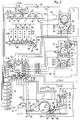
- Fiber flakes from fiber bales 2 are removed from a bale removal device 1 and fed via a conveyor path 3 to a first cleaning machine, for example a coarse cleaning machine 4.
- a first cleaning machine for example a coarse cleaning machine 4.
- the amount of flakes conveyed can be determined per unit of time, for example m3 / h, using a measuring device 54.
- this quantity measurement is not restricted to this example; there is also the possibility of directly relating this quantity to bring with the removal device 1 or to omit this measurement entirely and to provide storage depots described later above each cleaning machine.
- a fiber wadding 9 passes from this feed device 8 into a card 11 via a chute 10.
- a card sliver 12 is transferred from this card to a can tray 13.
- the bale removal device 1 is a machine which is sold worldwide by the applicant under the brand name UNIFLOC. It is therefore known per se, so that only the features essential for understanding the invention are listed.
- Such a bale removal device 1 comprises at least one rotating removal milling roller 14, which removes fiber flakes from the surface of the fiber bales 2 when moving back and forth according to the arrows 15 and, for example, pneumatically conveys them further, in our example via the conveying path 3.
- the coarse cleaning machine 4 comprises a cleaning roller 16, to which striking pins 17 are fastened on the circumference. These striking pins convey the delivered fiber flakes in a manner known per se via cleaning rods 18 which are arranged over part of the circumference of the cleaning roller 16. The position of these cleaning rods can be adjusted in such a way that the cleaning intensity can be changed. This changeability is shown schematically by the dash-dotted line 19.
- a brightness sensor or an ultrasound sensor 20 measures the brightness or sound reflection as a measure of the proportion of dirt in the excreted outlet which has been excreted by the cleaning rods 18 and is collected in a collecting trim 21.
- This collecting trim is in two parts, the lower part 22 being freely movable relative to the upper part 23 and being supported on measuring pressure sockets 24. As a result, the lower part 22 becomes the weighing container for the aforementioned outlet.
- the outlet is suctioned off via a suction transport 55 at predetermined time intervals. During this time, the weight measurement of the outlet is interrupted.
- the amount of waste can also be determined indirectly via a volume measurement per unit of time using light barriers, taking into account the density, which is variable as a function of the dirt content.
- the fine cleaning machine 6 comprises a cleaning roller 25, which optionally with sawtooth sets or others Sets are provided to dissolve the supplied fiber flakes even more finely than was done in the above-mentioned coarse cleaning machine.
- the fiber flakes are fed to the cleaning roller 25 by means of a feed roller 26 and a feed plate 27 which cooperates therewith and can be pivoted about a pivot axis 50.
- the functions of such an infeed are known per se and are not further described, but it should be mentioned that the feed plate 27 is pressed with a predetermined force in the direction of the feed roller and that the pivot axis 50 about the axis of rotation 51 of the feed roller 26 in a predetermined mass in the Arrow directions S and S.1 is pivotable, which is marked with the radius R.
- This pivotability enables the clamping line of the fibers fed in between the feed roller 26 and the fiber delivery edge 52 of the feed plate to be displaced at the periphery of the feed roller 26, so that short fibers with a more advanced, seen in the fiber conveying direction, and long fibers with a more advanced displacement line be fed. In contrast to a stationary clamping line, this measure can completely avoid fiber cuts during feeding.
- the feed roller can be moved spring-loaded against the plate.
- the feed plate is arranged in a fixed path (not shown) pivotable about a given axis of rotation of the feed roller.
- the fiber flakes fed to the cleaning roller are picked up by the latter and guided past cleaning elements 28, which are arranged around part of the circumference of the cleaning roller 25.
- These cleaning elements can be carding elements or knives with and without baffles between the knives etc.
- the fine cleaning machine 6 also comprises in its lower part a trimelle divided into an upper part 23.1 and lower part 22.1 for collecting the waste product, this trimelle 21.1 also being supported in the manner described on pressure measuring cells 24.1.
- the brightness is also measured by a brightness sensor 20.1 and the outlet is suctioned off by a suction transport 55.1.
- an ultrasonic sensor can replace the brightness sensor or the volume measurement instead of the weight measurement.
- the rectangle identified by 30 and drawn with dash-dotted lines is intended to show that there may also be further cleaning machines or machines with cleaning functions analogous or similar to the fine cleaning machine 6, which means that the invention does not apply to the machine combination shown in the figure is restricted.
- the feed device 8 comprises a feed shaft 31 and two feed rollers 32, which feed the fiber flakes to a dissolving roller 33, by means of which the fiber flakes are further reduced, i.e. to be further resolved.
- the fiber wadding 9 is further fed in a manner known per se from the feed roller 37 to a toothbrush roller 39 provided with a set of teeth, by means of which the fiber wadding 9 is dissolved in a thin nonwoven fabric and is fed to the drum roll 40.
- the beater roller 39 can have cleaning elements 41 on a part of its circumference, the intensity of which can be adjusted.
- the adjustability of these cleaning elements 41 is shown schematically by the dash-dotted line 42.
- the cleaning outlet of these cleaning elements 41 is a finer outlet than that of the fine cleaning machine, i.e. that the cleaning intensity is adjusted accordingly.
- a weighing bowl 59 which is supported on pressure measuring sockets 58 and is connected to a suction transport 60, is provided for collecting and measuring this cleaning outlet.
- the proportion of actual dirt in the outlet is measured by means of a brightness sensor 20.2 or a corresponding ultrasonic sensor and is analogous to the suction 55 or. 55.1 vacuumed periodically.
- the fleece lying on the drum roll 40 is taken over by a doffer roll 43 and between the subsequent rolls and a fleece compactor 44 Card sliver 12 compressed.
- This card sliver 12 is further checked in a measuring funnel 46 for the fineness (micronaire) of the fibers of the card sliver 46.
- a pair of measuring rollers 47 emits the sliver quantity per unit of time (meters / min) as signal S.47, which will be described later.
- the card sliver 12 is checked for its color by means of a color sensor 48 before it is entered into the can deposit 13.
- optimization can be carried out with the aid of a microcomputer control 53.
- the named priority is determined by input (not shown) into the control.
- the desired performance and the desired degree of cleaning are included Priority entered, so that the computer, on the one hand, calculates and displays and / or automatically sets the information for the setting of the above-mentioned work elements on the basis of the input data and the dirt content entered, and on the other hand displays the calculated possible fiber impairment.
- the operating personnel then have the option of accepting this value or, if not, of making a correction either in the value of the degree of cleaning or in the value of the output, with the result that the computer immediately changes the new value of the possible ones when the work elements are set again Calculates fiber impairment. This can be repeated until the three variables show acceptable values. This applies to a fixed fiber bale template with the mean values of the output data calculated from it. The decision whether the values of the three variables are acceptable or not depends on the type of yarn to be produced or. the type of use of the yarn.
- the computer is additionally programmed by entering the use of the yarn.
- This input (not shown) is input with the first priority, whereby the degree of cleaning and the fiber impairment are essentially given, so that given the output data and the dirt content, the performance calculated from this must be accepted.
- the fiber bale template is adapted by selecting other bale provenances until the three variables are within the tolerated ranges based on new output data.
- this can be done by recalculating the mean value of the individual output data and entering this output data into the computer.
- the computer is provided in such a way that the output data of each bale provenance from a selection of bale provenances is entered into the computer and the computer by entering either the degree of cleaning of the performance and the tolerated fiber impairment or the use of the yarn and the Performance selects the bale provenance itself. These entries of the original data are made by provenance on keyboards described later.
- Another additional variant consists in entering the costs (not shown) of the individual fiber bale provenances in the fiber bale template and a specified value for the yarn to be produced, in order to either maintain the profit margin within a predetermined range with an increased tolerance with regard to purity and fiber impairment or to accept the profit margin with normal tolerance regarding purity and fiber impairment.
- the input of the initial data, the proportion of the types of dirt, the degree of cleaning, the throughput and the presumed Fiber impairment occurs via correspondingly suitable digital keyboards or analog sliders (eg potentiometers), which are only shown schematically and are identified in the figure with the letters St, M, F, D, GR, FR, RG, L and FB.
- digital keyboards or analog sliders eg potentiometers
- These inputs are entered into the controller via the input signals st, m, f, d, gr, fr, rg, l and fb.
- the inputs of the signals rg, l and fb are shown on the displays A.RG, AL and A.FB in such a way that, for example, the output L in kg / h, the degree of cleaning RG in percent and the putative fiber impairment, which is practically in of a fiber shortening, are stated in percent of the stack length St.
- the computer calculates the setting values for the work elements and shows these setting values on the corresponding displays.
- the operating staff causes the setting of the work elements, while in the "automatic variant" this setting is initiated by the computer.
- the computer 53 For the bale removal device 1, the computer 53 outputs an output signal S.14, which determines the speed of the removal milling drum 14. This speed is shown on the display A.14. Another signal. S.15 determines the feed speed in the feed directions 15 and shows this feed speed, for example in meters / min, on the display A.15. A third signal S.61 determines the specific penetration depth of the roller 14.
- S.14 determines the speed of the removal milling drum 14.
- Another signal. S.15 determines the feed speed in the feed directions 15 and shows this feed speed, for example in meters / min, on the display A.15.
- a third signal S.61 determines the specific penetration depth of the roller 14.
- the penetration depth is understood at the beginning of the removal, since during the removal the penetration depth is changed due to the changing density of the fiber bales depending on the remaining height of the fiber bales due to a machine's own control. Such a control is published in EP Patent No. 193,647. It goes without saying that given a variable and /
- the computer 53 emits a signal S.16, which influences the speed of the cleaning roller 16 and is displayed on a display A.16, while a signal S.19 causes the setting of the cleaning rods 18 and this setting, for example, with a characteristic angle (not shown) on the display A.19.
- the brightness of the precipitated waste measured by the brightness sensor 20 is input into the controller 53 as signal S.20 and displayed on a display A.20.
- the weight determined by the pressure measuring cells 24 is entered into the controller 53 by means of a signal S.24 and displayed on a display A.24. The measurement takes place during predefined time intervals, so that the weight displayed is a summation of the resulting waste in this time interval.
- the computer displays the values for the speed of the cleaning roller 25 on a display A.25 and causes the corresponding speed by means of a signal S.25, while the setting of the cleaning elements 28 is displayed by means of a display A.29 and set by means of the signal p.29 becomes.
- the display A.29 depends on the type of cleaning element 28. For example, the percentage intensity can be displayed for cleaning elements with adjustable intensity.
- the brightness measuring device 20.1 outputs a signal S.20.1 corresponding to the brightness of the deposited waste into the controller 53, which is shown on a display A.20.1 as well as a signal S.24.1 which is displayed on a display A.24.1 and the weight signal of the Pressure cells 24.1 is.
- the outlet of the fine cleaning machine 6 is also collected over a time interval in the weighing container 22.1 and entered into the control as a weight signal via the aforementioned signal S.24.1.
- This machine has a further signal S.50, which is emitted by the controller 53 and ensures the correct position of the pivot axis 50 in accordance with the stack length of the fibers to be processed.
- the speed of the opening roller 33 in the feed device 8 can be controlled with the aid of the signal S.33 from the controller 53, which in this case is indicated as optional with the dashed line.
- the performance of the entire system is primarily dictated by the performance of the card 11, specifically by the speed of the feed roller 37. As already mentioned, this performance is either entered into the control system by the input L by means of the signal 1 and on the display AL displayed and caused by a signal p.37 or according to the previously mentioned assignment of priorities depending on the assigned priorities and the corresponding invoice only displayed and set accordingly, ie automatically caused by the signal p.37.
- a further control of the performance of the system can be carried out by the quantity measuring device 54 in the conveying path 3, which determines the amount of flakes removed per time unit by the bale removal device 1 and inputs it into the control by means of a signal S.54 and displays it on a display A.54.
- This performance monitoring with the aid of the card and the measuring device 54, combined with the monitoring of the discharged outlet on the cleaning machines 4 and 6, is essential if the product transported in the system from machine to machine works without a depot container above the cleaning machines. If, as a variant, the cleaning machines work in stop / go mode, depot containers are provided above the cleaning machines.
- the performance monitoring by means of the measuring device 54 is also advantageous in the latter case because the stop times in stop / go operation can thereby be kept as short as possible.
- the aforementioned depot containers can correspond to the feed device 8 with the omission of the pressure roller 36.
- the stop / go operation is controlled by means of the light barriers 56 and 57, which scan the level of the fiber flakes in the lower shaft 34 and thereby switch off the machine preceding the flake run at the level of the light barrier 56 and switch it on again at the level of the light barrier 57. It goes without saying that the more precisely the performance monitoring by means of the measuring device 54 and the waste monitoring by means of the pressure load cells 24 and 24.1 resp. 58 is carried out, the less frequently the cleaning machines switch on and off.
- a further monitored possibility of cleaning the fibers to be processed is in the card by means of the cleaning elements 41, which, as already mentioned, are adjustable in their cleaning intensity, and this adjustability is indicated schematically by the dash-dotted line 42.
- This cleaning intensity of the cleaning elements 41 is transmitted from the controller 53 to the cleaning elements 41 via a signal S.42.
- the brightness of the input measured by the sensor 20.2 is entered into the control by means of the signal S.20.2 and the weight measured by the pressure measuring sockets 58 by means of the signal S.58 and from there by the display A.20.2 or. A.58 displayed.
- the performance of the card is also given by the doffer roller 43, which is why the speed of this roller is controlled by the controller 53 by means of a signal S.43 and is shown in a display A.43.
- the fineness of the fibers in the fiber sliver enters the control 53 as a signal S.46 from the measuring funnel 46 with a corresponding display A.46.
- This measurement is a check of the applicable Fiber bale template, that means the right combination of fiber bale provenances.
- the actual card sliver output (meter / h) is measured with the aid of the pair of measuring rollers 47, the signal S.47 of which enters the controller 53 with the display A.47.
- a further control of the entire mixture of the bale provenances, opening and cleaning process takes place with the brightness control of the color sensor 48, which scans the card sliver 12 for its color and / or brightness and is entered into the control system by means of a signal S.48 and is indicated with a display A. 48 is displayed.
- This check does not affect the cleaning effect of the previous machines, but the basic color of the fibers, i.e. the correct composition of the fiber bale template. If the color in this control is not correct, an alarm is given to the operating personnel if the bale template is not automatically selected, otherwise the computer determines the changed bale template. This check is only possible at this point, as it would be falsified in previous runs of the not yet completely cleaned fiber material due to residual contamination.
- the temperature and humidity of the room can also be taken into account for the calculation and displayed using the A.T. resp. A.Fe appear.
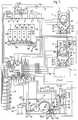
- Figure 2 shows, compared to Figure 1, a variant according to this invention, according to which the fiber bales with the Provenances A, B, C, D and E are marked and a predetermined distance Z described later is provided between the fiber bales.
- Branches 62 are provided in the conveyor path 5.1, so that the component depots 63 can be controlled directly.
- such branches can be so-called pipe switches.
- Each component depot 63 has a pair of discharge rollers 64, by means of which the fiber flakes located in the depot are discharged and placed on a conveyor belt 65.
- the fiber flakes from all component depots 63 are collected as layers lying on top of one another, as can be seen in FIG. 2, and conveyed against a compression element 66, for example a small conveyor belt, by means of which the conveyor belt 65 covers the entire fiber layer with a dissolving element 67 Opening roller 68 feeds. With the help of this dissolving element and an sucked-in air flow 69, the flakes are conveyed in a conveying path 70 into the fine cleaning machine 6.
- the layer can be put directly into the fine cleaning machine 6.
- the control of the 53.1 contains the same microcomputer for the calculation as the control 53, but additionally has the possibility that the natural output data of the fibers per provenance are entered into the control so that the computer adjusts the setting of the working elements of the coarse cleaning machine 4 per provenance .
- the distance Z has a correspondingly predetermined size. This changeover of the working elements can take place either only in one displacement direction 15 of the bale removal device 1 or in both displacement directions, depending on whether removal is carried out only in one or in both directions 15.
- the measuring device 54 for monitoring the removal performance of the bale removal device 1 has the same function as in the arrangement of FIG. 1, since the photocells 56 and 57 are only provided in the depots 63 for security purposes in order to report malfunctions in the delivery or in the delivery performance.
- the photocells 56 and 57 are therefore also connected to the controller 53.1 (not shown).
- discharge capacity of the discharge rollers 64 as well as the conveying capacity of the conveyor belts 65 and 66 and the speed of the opening roller 68 are controlled by the controller 53.1.
- the advantage of this variant is that the individual provenances can be cleaned differently and that a more homogeneous mixture of the individual fiber provenances is created.
- FIG. 3 shows a variant compared to FIG. 2 in that the individual provenances are also cleaned by the fine cleaning machine before they are conveyed to the component depots 63. Accordingly, the fiber flakes are conveyed from the fine cleaning machine 6 by means of a conveying path 7.1 via the branches 62 into the component depots 63. After the provenances have been mixed, the fiber flakes are then fed to the dissolving element 67 by means of a conveying path 70 of the feed device 8.
- the control is labeled 53.2 according to this variant.
- the advantage of this variant is the possibility of having the fiber flakes of the individual provenances cleaned by the coarse as well as the fine cleaning machine before a mixture of the individual provenances is put together.
- FIG. 2 it is also indicated by the dash-dotted lines 72 and 73 that the product of the bale removal device 1 can first be conveyed into the component depots 63, in order then to arrive in the coarse cleaning machine 4 as a mixture.
Landscapes
- Engineering & Computer Science (AREA)
- Textile Engineering (AREA)
- Preliminary Treatment Of Fibers (AREA)
Applications Claiming Priority (4)
| Application Number | Priority Date | Filing Date | Title |
|---|---|---|---|
| CH192989 | 1989-05-23 | ||
| CH1929/89 | 1989-05-23 | ||
| CH192989 | 1989-05-23 | ||
| EP90108959A EP0399315B1 (fr) | 1989-05-23 | 1990-05-12 | Opération de nettoyage optimal |
Related Parent Applications (2)
| Application Number | Title | Priority Date | Filing Date |
|---|---|---|---|
| EP90108959A Division EP0399315B1 (fr) | 1989-05-23 | 1990-05-12 | Opération de nettoyage optimal |
| EP90108959.9 Division | 1990-05-12 |
Publications (2)
| Publication Number | Publication Date |
|---|---|
| EP0641876A1 true EP0641876A1 (fr) | 1995-03-08 |
| EP0641876B1 EP0641876B1 (fr) | 2002-07-31 |
Family
ID=4221889
Family Applications (2)
| Application Number | Title | Priority Date | Filing Date |
|---|---|---|---|
| EP90108959A Expired - Lifetime EP0399315B1 (fr) | 1989-05-23 | 1990-05-12 | Opération de nettoyage optimal |
| EP94114935A Expired - Lifetime EP0641876B1 (fr) | 1989-05-23 | 1990-05-12 | Optimisation du nettoyage |
Family Applications Before (1)
| Application Number | Title | Priority Date | Filing Date |
|---|---|---|---|
| EP90108959A Expired - Lifetime EP0399315B1 (fr) | 1989-05-23 | 1990-05-12 | Opération de nettoyage optimal |
Country Status (8)
| Country | Link |
|---|---|
| EP (2) | EP0399315B1 (fr) |
| JP (1) | JPH0314631A (fr) |
| CN (1) | CN1023330C (fr) |
| AU (1) | AU636884B2 (fr) |
| CS (1) | CS246290A3 (fr) |
| DD (1) | DD296115A5 (fr) |
| DE (2) | DE59010929D1 (fr) |
| ZA (1) | ZA903649B (fr) |
Cited By (6)
| Publication number | Priority date | Publication date | Assignee | Title |
|---|---|---|---|---|
| EP0810309A1 (fr) * | 1996-05-20 | 1997-12-03 | Maschinenfabrik Rieter Ag | Installation pour le traitement de fibres |
| WO2000026449A1 (fr) * | 1998-11-02 | 2000-05-11 | Autefa Maschinenfabrik Gmbh | Installation de traitement de fibres |
| EP1057907A1 (fr) * | 1999-05-31 | 2000-12-06 | Barco N.V. | Procédés et systèmes de controlle d'opération de filature |
| US6421883B1 (en) | 1999-11-24 | 2002-07-23 | Maschinenfabrik Rieter Ag | Selective cleaning line |
| FR2841909A1 (fr) * | 2002-07-08 | 2004-01-09 | Truetzschler Gmbh & Co Kg | Procede et appareil de nettoyage pour machine de preparation au filage |
| DE102018127621A1 (de) * | 2018-11-06 | 2020-05-07 | HELLA GmbH & Co. KGaA | Schaltungsanordnung zur Begrenzung eines Einschaltstroms |
Families Citing this family (18)
| Publication number | Priority date | Publication date | Assignee | Title |
|---|---|---|---|---|
| EP0452676B1 (fr) * | 1990-03-22 | 1998-12-16 | Maschinenfabrik Rieter Ag | Champ d'identification de nettoyage |
| DE4018803A1 (de) * | 1990-06-12 | 1991-12-19 | Rieter Ag Maschf | Verfahren und vorrichtung zur regelung eines oeffnungsvorganges, beispielsweise an einer karde |
| US5509179A (en) * | 1990-06-25 | 1996-04-23 | Mondini; Giancarlo | Autoleveller draw frame having process feed back control system |
| EP0483607B1 (fr) * | 1990-11-02 | 1997-04-23 | Maschinenfabrik Rieter Ag | Procédé pour identifier la qualité d'un matériau fibreux |
| AR001448A1 (es) | 1995-03-27 | 1997-10-22 | Grupo Cydsa Sa De Cv | Lamina o película termoplastica encogible por calor y metodos para proteger recipientes empleando dicha lamina o película. |
| DE19630018A1 (de) * | 1996-07-25 | 1998-01-29 | Rieter Ag Maschf | Anlage zum Verarbeiten von Fasern |
| DE10063861B4 (de) | 2000-12-21 | 2014-08-28 | Trützschler GmbH & Co Kommanditgesellschaft | Vorrichtung an einer Spinnereivorbereitungsmaschine, z. B. Reiniger, Öffner, Karde o. dgl. zur Erfassung von ausgeschiedenem Abfall |
| CH697063A5 (de) * | 2003-04-03 | 2008-04-15 | Truetzschler Gmbh & Co Kg | Vorrichtung an einer Spinnereivorbereitungsmaschine, z.B. Reiniger, Öffner oder Karde, zur Erfassung von aus Fasermaterial, z. B. Baumwolle, ausgeschiedenem, aus Fremdstoffen und Gutfasern b |
| DE10349407B4 (de) * | 2003-04-03 | 2017-06-14 | Trützschler GmbH & Co Kommanditgesellschaft | Vorrichtung an einer Spinnereivorbereitungsmaschine, z. B. Reiniger, Öffner, Karde oder dergleichen zur Erfassung von aus Fasermaterial, z. B. Baumwolle, ausgeschiedenem Abfall |
| CN103008248A (zh) * | 2011-09-25 | 2013-04-03 | 陈华松 | 棉花收获机械中的清理方法与机构 |
| CH712382A1 (de) * | 2016-04-21 | 2017-10-31 | Rieter Ag Maschf | Verfahren zum Betrieb eines Ballenöffners und Ballenöffner. |
| DE102019115138B3 (de) * | 2019-06-05 | 2020-12-10 | TRüTZSCHLER GMBH & CO. KG | Karde, Vliesleitelement, Spinnereivorbereitungsanlage und Verfahren zur Erfassung von störenden Partikeln |
| CH717716A1 (de) | 2020-08-05 | 2022-02-15 | Rieter Ag Maschf | Erfassung des Abganges in einer Faservorbereitungsanlage. |
| CH717715A1 (de) | 2020-08-05 | 2022-02-15 | Rieter Ag Maschf | Faservorbereitungsmaschine mit einer Kamera. |
| CN114351436A (zh) * | 2021-11-29 | 2022-04-15 | 含山县光乾纺织有限公司 | 一种棉纺织品加工用梳棉除杂机构 |
| CN114622308A (zh) * | 2022-03-14 | 2022-06-14 | 王陶 | 一种基于人工智能的纺织过程自适应清棉系统 |
| CH720832A1 (de) * | 2023-06-06 | 2024-12-13 | Rieter Ag Maschf | Verfahren zum Einstellen einer Vielzahl von Reinigungsstellen in einer Faservorbereitungsanlage |
| CN120967556B (zh) * | 2025-10-22 | 2025-12-26 | 南通丰然纺织有限公司 | 基于多设备协同的清棉机工作质量自测控制方法 |
Citations (3)
| Publication number | Priority date | Publication date | Assignee | Title |
|---|---|---|---|---|
| US3894314A (en) * | 1973-01-29 | 1975-07-15 | James E Nayfa | Treatment of spinning fibers in a textile mill |
| FR2534600A1 (fr) * | 1982-10-13 | 1984-04-20 | Truetzschler & Co | Procede et dispositif de commande et/ou regulation d'une installation de preparation a la filature |
| EP0311831A1 (fr) * | 1987-10-08 | 1989-04-19 | Maschinenfabrik Rieter Ag | Régulation des étapes d'ouverture de fibres d'une installation de préparation à la filature |
Family Cites Families (1)
| Publication number | Priority date | Publication date | Assignee | Title |
|---|---|---|---|---|
| EP0312805B1 (fr) * | 1987-10-07 | 1991-11-21 | Maschinenfabrik Rieter Ag | Commande de production |
-
1990
- 1990-05-03 AU AU54648/90A patent/AU636884B2/en not_active Ceased
- 1990-05-12 EP EP90108959A patent/EP0399315B1/fr not_active Expired - Lifetime
- 1990-05-12 DE DE59010929T patent/DE59010929D1/de not_active Expired - Fee Related
- 1990-05-12 EP EP94114935A patent/EP0641876B1/fr not_active Expired - Lifetime
- 1990-05-12 DE DE59009762T patent/DE59009762D1/de not_active Expired - Fee Related
- 1990-05-14 ZA ZA903649A patent/ZA903649B/xx unknown
- 1990-05-21 CS CS902462A patent/CS246290A3/cs unknown
- 1990-05-22 JP JP2130442A patent/JPH0314631A/ja active Pending
- 1990-05-22 DD DD90340907A patent/DD296115A5/de not_active IP Right Cessation
- 1990-05-23 CN CN90103906A patent/CN1023330C/zh not_active Expired - Lifetime
Patent Citations (3)
| Publication number | Priority date | Publication date | Assignee | Title |
|---|---|---|---|---|
| US3894314A (en) * | 1973-01-29 | 1975-07-15 | James E Nayfa | Treatment of spinning fibers in a textile mill |
| FR2534600A1 (fr) * | 1982-10-13 | 1984-04-20 | Truetzschler & Co | Procede et dispositif de commande et/ou regulation d'une installation de preparation a la filature |
| EP0311831A1 (fr) * | 1987-10-08 | 1989-04-19 | Maschinenfabrik Rieter Ag | Régulation des étapes d'ouverture de fibres d'une installation de préparation à la filature |
Cited By (10)
| Publication number | Priority date | Publication date | Assignee | Title |
|---|---|---|---|---|
| EP0810309A1 (fr) * | 1996-05-20 | 1997-12-03 | Maschinenfabrik Rieter Ag | Installation pour le traitement de fibres |
| US6212737B1 (en) | 1996-05-20 | 2001-04-10 | Maschinenfabrik Rieter Ag | Plant for processing fibers |
| WO2000026449A1 (fr) * | 1998-11-02 | 2000-05-11 | Autefa Maschinenfabrik Gmbh | Installation de traitement de fibres |
| EP1057907A1 (fr) * | 1999-05-31 | 2000-12-06 | Barco N.V. | Procédés et systèmes de controlle d'opération de filature |
| US6421883B1 (en) | 1999-11-24 | 2002-07-23 | Maschinenfabrik Rieter Ag | Selective cleaning line |
| FR2841909A1 (fr) * | 2002-07-08 | 2004-01-09 | Truetzschler Gmbh & Co Kg | Procede et appareil de nettoyage pour machine de preparation au filage |
| DE10230603A1 (de) * | 2002-07-08 | 2004-01-29 | Trützschler GmbH & Co KG | Verfahren und Vorrichtung an einer Spinnereivorbereitungsmaschine, z.B. Reiniger, Öffner, Karde o. dgl., zur Reinigung von Fasergut |
| US6865781B2 (en) | 2002-07-08 | 2005-03-15 | Trutzchler Gmbh & Co. Kg | Method and apparatus at a spinning preparation machine for cleaning fiber material |
| DE10230603B4 (de) * | 2002-07-08 | 2017-06-14 | Trützschler GmbH & Co Kommanditgesellschaft | Verfahren und Vorrichtung an einer Spinnereivorbereitungsmaschine, z.B. Reiniger, Öffner, Karde o. dgl., zur Reinigung von Fasergut |
| DE102018127621A1 (de) * | 2018-11-06 | 2020-05-07 | HELLA GmbH & Co. KGaA | Schaltungsanordnung zur Begrenzung eines Einschaltstroms |
Also Published As
| Publication number | Publication date |
|---|---|
| CN1048901A (zh) | 1991-01-30 |
| AU636884B2 (en) | 1993-05-13 |
| DE59010929D1 (de) | 2002-09-05 |
| JPH0314631A (ja) | 1991-01-23 |
| EP0399315A1 (fr) | 1990-11-28 |
| CN1023330C (zh) | 1993-12-29 |
| DD296115A5 (de) | 1991-11-21 |
| AU5464890A (en) | 1990-11-29 |
| ZA903649B (en) | 1991-02-27 |
| EP0641876B1 (fr) | 2002-07-31 |
| DE59009762D1 (de) | 1995-11-16 |
| CS246290A3 (en) | 1992-01-15 |
| EP0399315B1 (fr) | 1995-10-11 |
Similar Documents
| Publication | Publication Date | Title |
|---|---|---|
| EP0399315B1 (fr) | Opération de nettoyage optimal | |
| EP0362538B1 (fr) | Procédé pour mélanger les fibres textiles | |
| EP1733080B1 (fr) | Cuve de nettoyage | |
| DE2728015C2 (de) | Verfahren und Vorrichtung zum Herstellen eines Faservlieses | |
| DE19516568A1 (de) | Vorrichtung in einer Spinnereivorbereitungseinrichtung (Putzerei) zum Erkennen und Ausscheiden von Fremdstoffen, z. B. Gewebestücke, Bänder, Schnüre, Folienstücke, in bzw. aus Fasergut | |
| DE2532061C2 (de) | Vorrichtung zur Beschickung einer Mehrzahl von Karden | |
| EP0361276B1 (fr) | Appareil et procédé pour préparer des fibres textiles nettoyées et en alimenter une machine textile | |
| DE102019115138B3 (de) | Karde, Vliesleitelement, Spinnereivorbereitungsanlage und Verfahren zur Erfassung von störenden Partikeln | |
| CH648872A5 (de) | Kardierwerk. | |
| EP0810309B1 (fr) | Installation pour le traitement de fibres | |
| EP0571572B1 (fr) | Peigneuse | |
| DE8915712U1 (de) | Vorrichtung zum Erzeugen eines Faservlieses aus Textilfasern, z. B. Baumwolle o.dgl. | |
| EP1167590A2 (fr) | Mesure de la longeur de fibres | |
| EP1123995A1 (fr) | Procede et appareil pour commander une installation de traitement de fibres textile, en particulier pour fibres de coton | |
| DE60109712T2 (de) | Deckelkard mit Mehrfachzufuhr von Fasern | |
| DE19530715A1 (de) | Verfahren und Anlage zur Herstellung von Faserbändern für Spinnmaschinen | |
| EP0409772A1 (fr) | Procédé de traitement optimal des fibres textiles d'une provenance différente | |
| DE1510391C3 (de) | Verfahren und Anlage zur Herstellung von Asbestvliesen | |
| CH683347A5 (de) | Steuerung bzw. Regelung einer Faserverarbeitungsanlage. | |
| DE4123179C2 (de) | Vorrichtung zur Verarbeitung von Fasermaterial | |
| WO2006086911A1 (fr) | Alimentation en bourres et dispositif d'alimentation en bourres | |
| EP1917388A1 (fr) | Systeme d'alimentation en flocons | |
| DE19630018A1 (de) | Anlage zum Verarbeiten von Fasern | |
| DE102005038405A1 (de) | Reinigungsvorrichtung | |
| EP0412446A1 (fr) | Procédé pour influencer le conditionnement des fibres traitées sur machine de filature |
Legal Events
| Date | Code | Title | Description |
|---|---|---|---|
| PUAI | Public reference made under article 153(3) epc to a published international application that has entered the european phase |
Free format text: ORIGINAL CODE: 0009012 |
|
| AC | Divisional application: reference to earlier application |
Ref document number: 399315 Country of ref document: EP |
|
| AK | Designated contracting states |
Kind code of ref document: A1 Designated state(s): CH DE ES FR GB IT LI |
|
| 17P | Request for examination filed |
Effective date: 19950203 |
|
| 17Q | First examination report despatched |
Effective date: 19960308 |
|
| GRAG | Despatch of communication of intention to grant |
Free format text: ORIGINAL CODE: EPIDOS AGRA |
|
| GRAG | Despatch of communication of intention to grant |
Free format text: ORIGINAL CODE: EPIDOS AGRA |
|
| GRAH | Despatch of communication of intention to grant a patent |
Free format text: ORIGINAL CODE: EPIDOS IGRA |
|
| GRAG | Despatch of communication of intention to grant |
Free format text: ORIGINAL CODE: EPIDOS AGRA |
|
| GRAH | Despatch of communication of intention to grant a patent |
Free format text: ORIGINAL CODE: EPIDOS IGRA |
|
| GRAA | (expected) grant |
Free format text: ORIGINAL CODE: 0009210 |
|
| AC | Divisional application: reference to earlier application |
Ref document number: 399315 Country of ref document: EP |
|
| AK | Designated contracting states |
Kind code of ref document: B1 Designated state(s): CH DE ES FR GB IT LI |
|
| PG25 | Lapsed in a contracting state [announced via postgrant information from national office to epo] |
Ref country code: GB Free format text: LAPSE BECAUSE OF FAILURE TO SUBMIT A TRANSLATION OF THE DESCRIPTION OR TO PAY THE FEE WITHIN THE PRESCRIBED TIME-LIMIT Effective date: 20020731 Ref country code: FR Free format text: LAPSE BECAUSE OF FAILURE TO SUBMIT A TRANSLATION OF THE DESCRIPTION OR TO PAY THE FEE WITHIN THE PRESCRIBED TIME-LIMIT Effective date: 20020731 |
|
| REG | Reference to a national code |
Ref country code: GB Ref legal event code: FG4D Free format text: NOT ENGLISH Ref country code: CH Ref legal event code: EP |
|
| REF | Corresponds to: |
Ref document number: 59010929 Country of ref document: DE Date of ref document: 20020905 |
|
| GBV | Gb: ep patent (uk) treated as always having been void in accordance with gb section 77(7)/1977 [no translation filed] |
Effective date: 20020731 |
|
| PG25 | Lapsed in a contracting state [announced via postgrant information from national office to epo] |
Ref country code: ES Free format text: LAPSE BECAUSE OF FAILURE TO SUBMIT A TRANSLATION OF THE DESCRIPTION OR TO PAY THE FEE WITHIN THE PRESCRIBED TIME-LIMIT Effective date: 20030130 |
|
| PG25 | Lapsed in a contracting state [announced via postgrant information from national office to epo] |
Ref country code: LI Free format text: LAPSE BECAUSE OF NON-PAYMENT OF DUE FEES Effective date: 20030531 Ref country code: CH Free format text: LAPSE BECAUSE OF NON-PAYMENT OF DUE FEES Effective date: 20030531 |
|
| PLBE | No opposition filed within time limit |
Free format text: ORIGINAL CODE: 0009261 |
|
| STAA | Information on the status of an ep patent application or granted ep patent |
Free format text: STATUS: NO OPPOSITION FILED WITHIN TIME LIMIT |
|
| 26N | No opposition filed |
Effective date: 20030506 |
|
| REG | Reference to a national code |
Ref country code: CH Ref legal event code: PL |
|
| PGFP | Annual fee paid to national office [announced via postgrant information from national office to epo] |
Ref country code: DE Payment date: 20050520 Year of fee payment: 16 |
|
| PGFP | Annual fee paid to national office [announced via postgrant information from national office to epo] |
Ref country code: IT Payment date: 20060531 Year of fee payment: 17 |
|
| PG25 | Lapsed in a contracting state [announced via postgrant information from national office to epo] |
Ref country code: DE Free format text: LAPSE BECAUSE OF NON-PAYMENT OF DUE FEES Effective date: 20061201 |
|
| PG25 | Lapsed in a contracting state [announced via postgrant information from national office to epo] |
Ref country code: IT Free format text: LAPSE BECAUSE OF NON-PAYMENT OF DUE FEES Effective date: 20070512 |