EP0642771A2 - Centrifugeuse - Google Patents
Centrifugeuse Download PDFInfo
- Publication number
- EP0642771A2 EP0642771A2 EP94117832A EP94117832A EP0642771A2 EP 0642771 A2 EP0642771 A2 EP 0642771A2 EP 94117832 A EP94117832 A EP 94117832A EP 94117832 A EP94117832 A EP 94117832A EP 0642771 A2 EP0642771 A2 EP 0642771A2
- Authority
- EP
- European Patent Office
- Prior art keywords
- centrifuge
- wall
- pump
- centrifuge according
- vanes
- Prior art date
- Legal status (The legal status is an assumption and is not a legal conclusion. Google has not performed a legal analysis and makes no representation as to the accuracy of the status listed.)
- Granted
Links
Images


Classifications
-
- A—HUMAN NECESSITIES
- A61—MEDICAL OR VETERINARY SCIENCE; HYGIENE
- A61C—DENTISTRY; APPARATUS OR METHODS FOR ORAL OR DENTAL HYGIENE
- A61C17/00—Devices for cleaning, polishing, rinsing or drying teeth, teeth cavities or prostheses; Saliva removers; Dental appliances for receiving spittle
- A61C17/06—Saliva removers; Accessories therefor
- A61C17/065—Saliva removers; Accessories therefor characterised by provisions for processing the collected matter, e.g. for separating solids or air
Definitions
- the invention relates to a centrifuge for separating fine solid particles from the wastewater accumulating at a dental work station according to the preamble of claim 1.
- the truncated cone-shaped guide wall which extends into the interior of the centrifuge drum, ensures that no direct fluid connection between the feed pipe to be broken down and the overflow opening of the centrifuge drum is possible as an extension of the cyclone wall.
- the known centrifuge works as a retrofit device, which is set up separately at a workplace, satisfactorily and with a good degree of separation, even for fine amalgam particles.
- the present invention is therefore intended to develop a centrifuge according to the preamble of claim 1 in such a way that an improvement in the separation performance is obtained with simple mechanical means, in particular without changing the drive in the case of small drum dimensions.
- the air separation cyclone also has smaller radial dimensions and there are additional sealing problems between the two with the centrifuge drum rotating and inside the same air discharge pipe and fixed housing parts.
- FIG. 1 shows a separation unit, designated overall by 10, which separates air fractions and solid particles from the wastewater generated at a dental work station.
- the solid particles are in particular amalgam particles, some of which have a very small diameter.
- the separating unit 10 has a first inlet connection 12, which is connected to the saliva lifter, also not shown, via the storage of the work station, not shown, and receives air-rich mixture to be dismantled.
- a second inlet connector 14 of the separation unit is connected to the cuspidor of the workplace and receives waste water containing only small amounts of air.
- the inlet ports 12 and 14 are molded onto an upper housing segment 16 which has a cylindrical cyclone wall 18 into which the inlet port 12 opens.
- a helical guide rib 20 is provided on its inner surface in the lower region.
- An air outlet chamber 22 is formed in the upper section of the housing segment 16 and is connected to an air outlet nozzle 24.
- the air outlet chamber 22 is closed at the top by the housing of an electric drive motor 26 which is carried by the housing segment 16.
- the drive motor 26 is additionally cooled by the outflowing clean air.
- a motor shaft 28 carries at its lower end a centrifuge drum, generally designated 30.
- a credit section 32 of the latter is connected to a peripheral wall 36 via radial webs 34.
- a funnel-shaped bottom wall 38 adjoins the latter at the bottom and delimits a circular sludge drain opening 40.
- a pump cone 41 extends through the latter at a greater radial distance and also represents a rotating part of the centrifuge drum 30.
- the centrifuge drum 30 rotates inside a central housing segment 42, which removably carries a collecting container 44 for separated amalgam at the lower end.
- Calming wings 46 molded onto the housing segment 42 extend around the pump cone 41 into the upper portion of the reservoir 44.
- a deflecting body 48 is formed on the hub section 32, the peripheral surface of which is conical and the upper end face has a circular cross-section.
- a conical guide wall 50 is also fixedly connected to the webs 34, the lower section of which is cylindrical and the upper section of which is conical.
- the angle which a generatrix of the guide wall 50 forms with the axis of the centrifuge drum 30 is between 3 and 7 °, preferably about 5 °.
- the upper end of the peripheral wall 36 carries a radially inwardly projecting overflow flange 52 which delimits an overflow opening 54.
- the lower section of the upper housing segment 16 is designed like a lid and tightly engages over the upper end of the middle housing segment 42.
- a sealing wall 56 hangs down from the top wall of this lid, the outside diameter of which is smaller than the diameter of the overflow opening 54, so that between the sealing wall 56 and an annular gap remains at the edge of the overflow opening 54.
- the inner surface of the sealing wall 56 is conical. Their angle of attack corresponds to that of the guide wall 50, and the entire arrangement is selected so that a narrow, elongated sealing gap remains between the guide wall 50 rotating together with the centrifuge drum 30 and the sealing wall 56.
- a second sealing wall 58 which is concentric with the sealing wall 56, but lies further inside, also hangs vertically downward, the outer surface of which is cylindrical and slightly inwardly bent upper end of the guide wall 50 penetrated with little running play.
- the motor shaft 28 Lying above the centrifuge drum 30, the motor shaft 28 carries an air discharge pipe 60 which is connected to a hub part 64 via three webs 62 distributed in the circumferential direction (cf. FIG. 5).
- the lower edge of the air discharge pipe 60 lies at the center of the circular trough forming the upper side of the deflecting body 48.
- the air discharge pipe 60 has a radial flange 66 which is fitted with pump vanes 68 on its upper side and with pump vanes 70 on its underside.
- the upper pump vanes 68 each have an acute-angled triangular recess 72, into which a locking rib 74 having an accordingly acute-angled triangular cross section can engage in close sliding play, which hangs from the underside of a cyclone end cover 76.
- the end cover 76 has a central, depending connection piece 78, which lies with little running play over the inner surface of the upper end of the air discharge pipe 60.
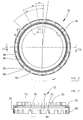
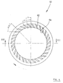
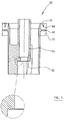
- the overflow flange 52 carries pump vanes 80 on its upper side. These are not arranged with constant angular division, rather the angular spacing of successive pump vanes statistically fluctuates around the mean value 11.
- the fluctuation range is +/- 2 °.
- a hanging apron 82 is formed on the outer edge of the overflow flange 52 and has windows 84 tapering towards the lower edge, so that individual pump vanes 86 result.
- the front and rear boundary surfaces 88, 90 of the windows 84 seen in the direction of rotation are the same Angle tilted against a radius beam drawn through its center, which is 45 ° in the exemplary embodiment under consideration.
- the division of the windows varies with an amplitude of +/- 2 ° statistically around an average of 17 °, while the division of the pump blades 86 independently fluctuates through +/- 2 ° around an average of 17 °.
- the underside of the overflow flange 52 also carries small pump blades 92 which are angularly aligned with the front edge of the rear boundary surface 90 of a window 84.
- the latter is connected to a pure water outlet connection 96, which is connected to the sewage system.
Landscapes
- Health & Medical Sciences (AREA)
- Dentistry (AREA)
- Epidemiology (AREA)
- Life Sciences & Earth Sciences (AREA)
- Animal Behavior & Ethology (AREA)
- General Health & Medical Sciences (AREA)
- Public Health (AREA)
- Veterinary Medicine (AREA)
- Centrifugal Separators (AREA)
Applications Claiming Priority (3)
| Application Number | Priority Date | Filing Date | Title |
|---|---|---|---|
| DE4121934A DE4121934A1 (de) | 1991-07-03 | 1991-07-03 | Zentrifuge |
| DE4121934 | 1991-07-03 | ||
| EP92110937A EP0524455B1 (fr) | 1991-07-03 | 1992-06-28 | Centrifugeuse |
Related Parent Applications (2)
| Application Number | Title | Priority Date | Filing Date |
|---|---|---|---|
| EP92110937.7 Division | 1992-06-28 | ||
| EP92110937A Division EP0524455B1 (fr) | 1991-07-03 | 1992-06-28 | Centrifugeuse |
Publications (3)
| Publication Number | Publication Date |
|---|---|
| EP0642771A2 true EP0642771A2 (fr) | 1995-03-15 |
| EP0642771A3 EP0642771A3 (fr) | 1996-09-18 |
| EP0642771B1 EP0642771B1 (fr) | 1999-06-09 |
Family
ID=6435287
Family Applications (2)
| Application Number | Title | Priority Date | Filing Date |
|---|---|---|---|
| EP94117832A Expired - Lifetime EP0642771B1 (fr) | 1991-07-03 | 1992-06-28 | Centrifugeuse |
| EP92110937A Expired - Lifetime EP0524455B1 (fr) | 1991-07-03 | 1992-06-28 | Centrifugeuse |
Family Applications After (1)
| Application Number | Title | Priority Date | Filing Date |
|---|---|---|---|
| EP92110937A Expired - Lifetime EP0524455B1 (fr) | 1991-07-03 | 1992-06-28 | Centrifugeuse |
Country Status (4)
| Country | Link |
|---|---|
| EP (2) | EP0642771B1 (fr) |
| AT (2) | ATE180958T1 (fr) |
| DE (4) | DE4143625B4 (fr) |
| ES (1) | ES2134308T3 (fr) |
Cited By (2)
| Publication number | Priority date | Publication date | Assignee | Title |
|---|---|---|---|---|
| US20100204032A1 (en) * | 2007-07-27 | 2010-08-12 | Bruno Pregenzer | Separator for separating air and from a dental waste water mixture |
| WO2022090553A3 (fr) * | 2020-11-02 | 2022-07-07 | Bruno Pregenzer | Séparateur à contenant de centrifugeuse amovible |
Families Citing this family (6)
| Publication number | Priority date | Publication date | Assignee | Title |
|---|---|---|---|---|
| AT399454B (de) * | 1993-03-10 | 1995-05-26 | Trawoeger Werner | Abscheider |
| DE4338718C2 (de) * | 1993-11-12 | 1996-12-12 | Duerr Dental Gmbh Co Kg | Abtrenneinheit für dentale Zwecke |
| DE4340193B4 (de) * | 1993-11-25 | 2004-02-26 | Dürr Dental GmbH & Co. KG | Saugeinheit für dentale Zwecke |
| DE102005018041B3 (de) * | 2005-04-19 | 2007-01-04 | Hanning Elektro-Werke Gmbh & Co. Kg | Antriebseinrichtung für eine Laborzentrifuge |
| DE102008047559A1 (de) * | 2008-09-16 | 2010-04-15 | DüRR DENTAL AG | Elektromotor |
| CN110231142B (zh) * | 2019-06-24 | 2024-07-02 | 苏州东菱科技有限公司 | 一种压力模拟试验装置 |
Family Cites Families (9)
| Publication number | Priority date | Publication date | Assignee | Title |
|---|---|---|---|---|
| US2222930A (en) * | 1939-04-14 | 1940-11-26 | Gerald D Arnold | Centrifugal separator |
| FR904052A (fr) * | 1943-12-10 | 1945-10-25 | Ventil Atel | Perfectionnements aux cyclones séparateurs |
| US3398866A (en) * | 1965-11-12 | 1968-08-27 | Gen Motors Corp | Dishwasher pump assembly with sound damped impeller |
| JPS6017296A (ja) * | 1983-07-08 | 1985-01-29 | Matsushita Electric Ind Co Ltd | 横断流送風機の羽根車 |
| SE442829B (sv) * | 1984-06-20 | 1986-02-03 | Scania Dental | Apparat for att separera luft och fasta partiklar fran en vetska |
| DE3588017D1 (de) * | 1984-12-17 | 1995-06-14 | Werner Trawoeger | Zahnärztlicher Abscheider. |
| DE3737002C1 (en) * | 1987-10-31 | 1989-01-26 | Emda | Device for precipitating fine particles of solids from waste water |
| JPH0214500U (fr) * | 1988-07-14 | 1990-01-30 | ||
| DE3916742C3 (de) * | 1989-05-23 | 2000-04-20 | Duerr Dental Gmbh Co Kg | Abscheideeinheit |
-
1991
- 1991-07-03 DE DE4143625A patent/DE4143625B4/de not_active Expired - Fee Related
- 1991-07-03 DE DE4121934A patent/DE4121934A1/de not_active Withdrawn
-
1992
- 1992-06-28 EP EP94117832A patent/EP0642771B1/fr not_active Expired - Lifetime
- 1992-06-28 DE DE59204983T patent/DE59204983D1/de not_active Expired - Fee Related
- 1992-06-28 AT AT94117832T patent/ATE180958T1/de not_active IP Right Cessation
- 1992-06-28 AT AT92110937T patent/ATE132729T1/de not_active IP Right Cessation
- 1992-06-28 ES ES94117832T patent/ES2134308T3/es not_active Expired - Lifetime
- 1992-06-28 EP EP92110937A patent/EP0524455B1/fr not_active Expired - Lifetime
- 1992-06-28 DE DE59209711T patent/DE59209711D1/de not_active Expired - Fee Related
Cited By (4)
| Publication number | Priority date | Publication date | Assignee | Title |
|---|---|---|---|---|
| US20100204032A1 (en) * | 2007-07-27 | 2010-08-12 | Bruno Pregenzer | Separator for separating air and from a dental waste water mixture |
| US8753253B2 (en) * | 2007-07-27 | 2014-06-17 | Bruno Pregenzer | Separator for separating air and solids from a dental waste water mixture |
| WO2022090553A3 (fr) * | 2020-11-02 | 2022-07-07 | Bruno Pregenzer | Séparateur à contenant de centrifugeuse amovible |
| CN116406317A (zh) * | 2020-11-02 | 2023-07-07 | 布鲁诺·普瑞根泽 | 具有可移除的离心机容器的分离器 |
Also Published As
| Publication number | Publication date |
|---|---|
| ATE180958T1 (de) | 1999-06-15 |
| ES2134308T3 (es) | 1999-10-01 |
| EP0642771A3 (fr) | 1996-09-18 |
| DE4143625B4 (de) | 2006-12-21 |
| DE59209711D1 (de) | 1999-07-15 |
| ATE132729T1 (de) | 1996-01-15 |
| DE59204983D1 (de) | 1996-02-22 |
| EP0642771B1 (fr) | 1999-06-09 |
| EP0524455B1 (fr) | 1996-01-10 |
| EP0524455A1 (fr) | 1993-01-27 |
| DE4121934A1 (de) | 1993-01-07 |
Similar Documents
| Publication | Publication Date | Title |
|---|---|---|
| EP0237708B1 (fr) | Dispositif d'aspiration dentaire | |
| EP0400431B1 (fr) | Dispositif séparateur | |
| DE1528763C3 (de) | Kreiselpumpe | |
| DE3521929C2 (fr) | ||
| AT395941B (de) | Abscheider zur trennung eines feststoff-fluessigkeitsgemisches | |
| DE202010010802U1 (de) | Feststoffabscheider | |
| EP0524455B1 (fr) | Centrifugeuse | |
| EP0680289B1 (fr) | Separateur de liquide | |
| WO2001012298A1 (fr) | Dispositif destine a separer des particules d'un fluide | |
| EP0224232B1 (fr) | Centrifugeuse à paroi pleine pour la séparation de particules solides fines | |
| WO2023148272A1 (fr) | Dispositif d'évacuation pour un ensemble récipient de réaction, centrifugeuse et procédé de nettoyage d'un ensemble récipient de réaction | |
| DE102008055046B3 (de) | Staubsauger mit einem Fliehkraftabscheider | |
| EP4171438B1 (fr) | Séparateur comprenant un élément d'étanchéité intégré pour la séparation fluide-air | |
| EP4042023B1 (fr) | Séparateur dental | |
| DE8533545U1 (de) | Gerät zum Abscheiden von Feststoffpartikeln aus Abwasser | |
| DE4338718A1 (de) | Abtrenneinheit und Saugeinheit für dentale Zwecke | |
| EP1285636B1 (fr) | Appareil séparateur | |
| DE10139026A1 (de) | Feststoff-Abscheidegerät | |
| DE1403834C (de) | Vorrichtung zum Abführen von Filtrat | |
| DE3542114A1 (de) | Zentrifuge zum abscheiden feiner feststoffpartikel aus abwasser | |
| DE3622168A1 (de) | Zentrifugalpumpe | |
| DE3510227A1 (de) | Stoffloeser | |
| DE19958514A1 (de) | Dentale Saugvorrichtung |
Legal Events
| Date | Code | Title | Description |
|---|---|---|---|
| PUAI | Public reference made under article 153(3) epc to a published international application that has entered the european phase |
Free format text: ORIGINAL CODE: 0009012 |
|
| AC | Divisional application: reference to earlier application |
Ref document number: 524455 Country of ref document: EP |
|
| AK | Designated contracting states |
Kind code of ref document: A2 Designated state(s): AT CH DE ES FR GB IT LI NL PT SE |
|
| PUAL | Search report despatched |
Free format text: ORIGINAL CODE: 0009013 |
|
| AK | Designated contracting states |
Kind code of ref document: A3 Designated state(s): AT CH DE ES FR GB IT LI NL PT SE |
|
| 17P | Request for examination filed |
Effective date: 19970312 |
|
| 17Q | First examination report despatched |
Effective date: 19980507 |
|
| GRAG | Despatch of communication of intention to grant |
Free format text: ORIGINAL CODE: EPIDOS AGRA |
|
| GRAG | Despatch of communication of intention to grant |
Free format text: ORIGINAL CODE: EPIDOS AGRA |
|
| GRAH | Despatch of communication of intention to grant a patent |
Free format text: ORIGINAL CODE: EPIDOS IGRA |
|
| GRAH | Despatch of communication of intention to grant a patent |
Free format text: ORIGINAL CODE: EPIDOS IGRA |
|
| GRAA | (expected) grant |
Free format text: ORIGINAL CODE: 0009210 |
|
| AC | Divisional application: reference to earlier application |
Ref document number: 524455 Country of ref document: EP |
|
| AK | Designated contracting states |
Kind code of ref document: B1 Designated state(s): AT CH DE ES FR GB IT LI NL PT SE |
|
| PG25 | Lapsed in a contracting state [announced via postgrant information from national office to epo] |
Ref country code: NL Free format text: LAPSE BECAUSE OF FAILURE TO SUBMIT A TRANSLATION OF THE DESCRIPTION OR TO PAY THE FEE WITHIN THE PRESCRIBED TIME-LIMIT Effective date: 19990609 |
|
| REF | Corresponds to: |
Ref document number: 180958 Country of ref document: AT Date of ref document: 19990615 Kind code of ref document: T |
|
| REG | Reference to a national code |
Ref country code: CH Ref legal event code: EP |
|
| GBT | Gb: translation of ep patent filed (gb section 77(6)(a)/1977) |
Effective date: 19990610 |
|
| REF | Corresponds to: |
Ref document number: 59209711 Country of ref document: DE Date of ref document: 19990715 |
|
| REG | Reference to a national code |
Ref country code: CH Ref legal event code: NV Representative=s name: FREI PATENTANWALTSBUERO |
|
| ITF | It: translation for a ep patent filed | ||
| PG25 | Lapsed in a contracting state [announced via postgrant information from national office to epo] |
Ref country code: PT Free format text: LAPSE BECAUSE OF FAILURE TO SUBMIT A TRANSLATION OF THE DESCRIPTION OR TO PAY THE FEE WITHIN THE PRESCRIBED TIME-LIMIT Effective date: 19990909 |
|
| ET | Fr: translation filed | ||
| REG | Reference to a national code |
Ref country code: ES Ref legal event code: FG2A Ref document number: 2134308 Country of ref document: ES Kind code of ref document: T3 |
|
| PLBE | No opposition filed within time limit |
Free format text: ORIGINAL CODE: 0009261 |
|
| STAA | Information on the status of an ep patent application or granted ep patent |
Free format text: STATUS: NO OPPOSITION FILED WITHIN TIME LIMIT |
|
| 26N | No opposition filed | ||
| REG | Reference to a national code |
Ref country code: GB Ref legal event code: IF02 |
|
| PGFP | Annual fee paid to national office [announced via postgrant information from national office to epo] |
Ref country code: GB Payment date: 20020625 Year of fee payment: 11 Ref country code: FR Payment date: 20020625 Year of fee payment: 11 Ref country code: CH Payment date: 20020625 Year of fee payment: 11 |
|
| PGFP | Annual fee paid to national office [announced via postgrant information from national office to epo] |
Ref country code: AT Payment date: 20020626 Year of fee payment: 11 Ref country code: ES Payment date: 20020626 Year of fee payment: 11 |
|
| PGFP | Annual fee paid to national office [announced via postgrant information from national office to epo] |
Ref country code: SE Payment date: 20030616 Year of fee payment: 12 |
|
| PG25 | Lapsed in a contracting state [announced via postgrant information from national office to epo] |
Ref country code: GB Free format text: LAPSE BECAUSE OF NON-PAYMENT OF DUE FEES Effective date: 20030628 Ref country code: AT Free format text: LAPSE BECAUSE OF NON-PAYMENT OF DUE FEES Effective date: 20030628 |
|
| PG25 | Lapsed in a contracting state [announced via postgrant information from national office to epo] |
Ref country code: LI Free format text: LAPSE BECAUSE OF NON-PAYMENT OF DUE FEES Effective date: 20030630 Ref country code: ES Free format text: LAPSE BECAUSE OF NON-PAYMENT OF DUE FEES Effective date: 20030630 Ref country code: CH Free format text: LAPSE BECAUSE OF NON-PAYMENT OF DUE FEES Effective date: 20030630 |
|
| PGFP | Annual fee paid to national office [announced via postgrant information from national office to epo] |
Ref country code: DE Payment date: 20030820 Year of fee payment: 12 |
|
| REG | Reference to a national code |
Ref country code: CH Ref legal event code: PL |
|
| GBPC | Gb: european patent ceased through non-payment of renewal fee |
Effective date: 20030628 |
|
| PG25 | Lapsed in a contracting state [announced via postgrant information from national office to epo] |
Ref country code: FR Free format text: LAPSE BECAUSE OF NON-PAYMENT OF DUE FEES Effective date: 20040227 |
|
| REG | Reference to a national code |
Ref country code: FR Ref legal event code: ST |
|
| PG25 | Lapsed in a contracting state [announced via postgrant information from national office to epo] |
Ref country code: SE Free format text: LAPSE BECAUSE OF NON-PAYMENT OF DUE FEES Effective date: 20040629 |
|
| REG | Reference to a national code |
Ref country code: ES Ref legal event code: FD2A Effective date: 20030630 |
|
| PG25 | Lapsed in a contracting state [announced via postgrant information from national office to epo] |
Ref country code: DE Free format text: LAPSE BECAUSE OF NON-PAYMENT OF DUE FEES Effective date: 20050101 |
|
| EUG | Se: european patent has lapsed | ||
| EUG | Se: european patent has lapsed | ||
| PG25 | Lapsed in a contracting state [announced via postgrant information from national office to epo] |
Ref country code: IT Free format text: LAPSE BECAUSE OF NON-PAYMENT OF DUE FEES Effective date: 20050628 |