EP0645132A1 - Massagegerät - Google Patents
Massagegerät Download PDFInfo
- Publication number
- EP0645132A1 EP0645132A1 EP94307062A EP94307062A EP0645132A1 EP 0645132 A1 EP0645132 A1 EP 0645132A1 EP 94307062 A EP94307062 A EP 94307062A EP 94307062 A EP94307062 A EP 94307062A EP 0645132 A1 EP0645132 A1 EP 0645132A1
- Authority
- EP
- European Patent Office
- Prior art keywords
- rotational
- massaging
- pressing member
- support
- pressing
- Prior art date
- Legal status (The legal status is an assumption and is not a legal conclusion. Google has not performed a legal analysis and makes no representation as to the accuracy of the status listed.)
- Withdrawn
Links
- 230000007246 mechanism Effects 0.000 claims abstract description 89
- 230000033001 locomotion Effects 0.000 claims description 33
- 230000002441 reversible effect Effects 0.000 claims description 6
- 238000010276 construction Methods 0.000 description 8
- 239000004744 fabric Substances 0.000 description 7
- 230000037431 insertion Effects 0.000 description 7
- 238000003780 insertion Methods 0.000 description 7
- 230000002093 peripheral effect Effects 0.000 description 6
- 230000007935 neutral effect Effects 0.000 description 4
- 239000004033 plastic Substances 0.000 description 4
- 239000000463 material Substances 0.000 description 3
- 230000000149 penetrating effect Effects 0.000 description 2
- 238000010079 rubber tapping Methods 0.000 description 2
- 229930182556 Polyacetal Natural products 0.000 description 1
- 238000010586 diagram Methods 0.000 description 1
- 239000013013 elastic material Substances 0.000 description 1
- 239000002184 metal Substances 0.000 description 1
- 229920006324 polyoxymethylene Polymers 0.000 description 1
- 239000011347 resin Substances 0.000 description 1
- 229920005989 resin Polymers 0.000 description 1
Images
















Classifications
-
- A—HUMAN NECESSITIES
- A61—MEDICAL OR VETERINARY SCIENCE; HYGIENE
- A61H—PHYSICAL THERAPY APPARATUS, e.g. DEVICES FOR LOCATING OR STIMULATING REFLEX POINTS IN THE BODY; ARTIFICIAL RESPIRATION; MASSAGE; BATHING DEVICES FOR SPECIAL THERAPEUTIC OR HYGIENIC PURPOSES OR SPECIFIC PARTS OF THE BODY
- A61H7/00—Devices for suction-kneading massage; Devices for massaging the skin by rubbing or brushing not otherwise provided for
-
- A—HUMAN NECESSITIES
- A61—MEDICAL OR VETERINARY SCIENCE; HYGIENE
- A61H—PHYSICAL THERAPY APPARATUS, e.g. DEVICES FOR LOCATING OR STIMULATING REFLEX POINTS IN THE BODY; ARTIFICIAL RESPIRATION; MASSAGE; BATHING DEVICES FOR SPECIAL THERAPEUTIC OR HYGIENIC PURPOSES OR SPECIFIC PARTS OF THE BODY
- A61H23/00—Percussion or vibration massage, e.g. using supersonic vibration; Suction-vibration massage; Massage with moving diaphragms
- A61H23/02—Percussion or vibration massage, e.g. using supersonic vibration; Suction-vibration massage; Massage with moving diaphragms with electric or magnetic drive
- A61H23/0254—Percussion or vibration massage, e.g. using supersonic vibration; Suction-vibration massage; Massage with moving diaphragms with electric or magnetic drive with rotary motor
-
- A—HUMAN NECESSITIES
- A61—MEDICAL OR VETERINARY SCIENCE; HYGIENE
- A61H—PHYSICAL THERAPY APPARATUS, e.g. DEVICES FOR LOCATING OR STIMULATING REFLEX POINTS IN THE BODY; ARTIFICIAL RESPIRATION; MASSAGE; BATHING DEVICES FOR SPECIAL THERAPEUTIC OR HYGIENIC PURPOSES OR SPECIFIC PARTS OF THE BODY
- A61H2201/00—Characteristics of apparatus not provided for in the preceding codes
- A61H2201/01—Constructive details
- A61H2201/0157—Constructive details portable
-
- A—HUMAN NECESSITIES
- A61—MEDICAL OR VETERINARY SCIENCE; HYGIENE
- A61H—PHYSICAL THERAPY APPARATUS, e.g. DEVICES FOR LOCATING OR STIMULATING REFLEX POINTS IN THE BODY; ARTIFICIAL RESPIRATION; MASSAGE; BATHING DEVICES FOR SPECIAL THERAPEUTIC OR HYGIENIC PURPOSES OR SPECIFIC PARTS OF THE BODY
- A61H2201/00—Characteristics of apparatus not provided for in the preceding codes
- A61H2201/14—Special force transmission means, i.e. between the driving means and the interface with the user
-
- A—HUMAN NECESSITIES
- A61—MEDICAL OR VETERINARY SCIENCE; HYGIENE
- A61H—PHYSICAL THERAPY APPARATUS, e.g. DEVICES FOR LOCATING OR STIMULATING REFLEX POINTS IN THE BODY; ARTIFICIAL RESPIRATION; MASSAGE; BATHING DEVICES FOR SPECIAL THERAPEUTIC OR HYGIENIC PURPOSES OR SPECIFIC PARTS OF THE BODY
- A61H2201/00—Characteristics of apparatus not provided for in the preceding codes
- A61H2201/14—Special force transmission means, i.e. between the driving means and the interface with the user
- A61H2201/1418—Cam
-
- A—HUMAN NECESSITIES
- A61—MEDICAL OR VETERINARY SCIENCE; HYGIENE
- A61H—PHYSICAL THERAPY APPARATUS, e.g. DEVICES FOR LOCATING OR STIMULATING REFLEX POINTS IN THE BODY; ARTIFICIAL RESPIRATION; MASSAGE; BATHING DEVICES FOR SPECIAL THERAPEUTIC OR HYGIENIC PURPOSES OR SPECIFIC PARTS OF THE BODY
- A61H2201/00—Characteristics of apparatus not provided for in the preceding codes
- A61H2201/14—Special force transmission means, i.e. between the driving means and the interface with the user
- A61H2201/1436—Special crank assembly
-
- A—HUMAN NECESSITIES
- A61—MEDICAL OR VETERINARY SCIENCE; HYGIENE
- A61H—PHYSICAL THERAPY APPARATUS, e.g. DEVICES FOR LOCATING OR STIMULATING REFLEX POINTS IN THE BODY; ARTIFICIAL RESPIRATION; MASSAGE; BATHING DEVICES FOR SPECIAL THERAPEUTIC OR HYGIENIC PURPOSES OR SPECIFIC PARTS OF THE BODY
- A61H2201/00—Characteristics of apparatus not provided for in the preceding codes
- A61H2201/16—Physical interface with patient
- A61H2201/1602—Physical interface with patient kind of interface, e.g. head rest, knee support or lumbar support
- A61H2201/1609—Neck
-
- A—HUMAN NECESSITIES
- A61—MEDICAL OR VETERINARY SCIENCE; HYGIENE
- A61H—PHYSICAL THERAPY APPARATUS, e.g. DEVICES FOR LOCATING OR STIMULATING REFLEX POINTS IN THE BODY; ARTIFICIAL RESPIRATION; MASSAGE; BATHING DEVICES FOR SPECIAL THERAPEUTIC OR HYGIENIC PURPOSES OR SPECIFIC PARTS OF THE BODY
- A61H2201/00—Characteristics of apparatus not provided for in the preceding codes
- A61H2201/16—Physical interface with patient
- A61H2201/1602—Physical interface with patient kind of interface, e.g. head rest, knee support or lumbar support
- A61H2201/1623—Back
-
- A—HUMAN NECESSITIES
- A61—MEDICAL OR VETERINARY SCIENCE; HYGIENE
- A61H—PHYSICAL THERAPY APPARATUS, e.g. DEVICES FOR LOCATING OR STIMULATING REFLEX POINTS IN THE BODY; ARTIFICIAL RESPIRATION; MASSAGE; BATHING DEVICES FOR SPECIAL THERAPEUTIC OR HYGIENIC PURPOSES OR SPECIFIC PARTS OF THE BODY
- A61H2201/00—Characteristics of apparatus not provided for in the preceding codes
- A61H2201/16—Physical interface with patient
- A61H2201/1683—Surface of interface
- A61H2201/1685—Surface of interface interchangeable
-
- A—HUMAN NECESSITIES
- A61—MEDICAL OR VETERINARY SCIENCE; HYGIENE
- A61H—PHYSICAL THERAPY APPARATUS, e.g. DEVICES FOR LOCATING OR STIMULATING REFLEX POINTS IN THE BODY; ARTIFICIAL RESPIRATION; MASSAGE; BATHING DEVICES FOR SPECIAL THERAPEUTIC OR HYGIENIC PURPOSES OR SPECIFIC PARTS OF THE BODY
- A61H2205/00—Devices for specific parts of the body
- A61H2205/04—Devices for specific parts of the body neck
Definitions
- the invention relates to an apparatus for massaging a specific portion of a human body to relieve fatigue or stiffness of the body portion.
- Massaging apparatuses or machines to relieve a stiffness in a specific portion of a body are well known and in widespread practical use.
- the massaging apparatus typically give a massage by tapping or vibrating the specific body portion.
- an apparatus for tapping on the shoulder an apparatus with a vibrator to vibrate on the body portion, an apparatus with a pair of arms to grasp and massage a body portion, and an apparatus with rollers which are pushed on a body portion and moved along the body are all known.
- the applicant of the present invention has a long experience in massaging the human body and found that the most effective way for massaging human body is to press a fingertip against a specific body portion and to move transversely the pressed fingertip on the body portion.
- the fingertip can be transversely moved so as to describe a circle locus, an ellipse locus or a locus of a figure "8".
- a massaging apparatus includes a massaging mechanism.
- the massaging mechanism comprises at least one pressing member for pressing against a specific location of a body portion, and means for moving the pressing member transversely across the specific location while the pressing member is pressed against the specific location.
- the massaging apparatus may further includes a support body for supporting the body portion. At least one massaging opening is formed in the support body for alignment with the specific location of a body portion placed on the support body.
- the massaging mechanism is provided inside the support body so that an upper end of the at least one pressing member is projecting outward through the massaging opening.
- the amount of outward projection of the pressing member through the massaging opening can be adjusted to adjust a pressing force applied by the pressing member against the specific location.
- a plurality of the pressing members may be provided so as to project through the massaging opening.
- the respective pressing members may be moved transversely by the transverse moving means.
- the support body may define a neck or a waist supporting portion by which a neck portion or a waist portion of the body can be supported.
- a pair of the massaging openings may be formed in the support body, and a pair of the massaging mechanisms may be mounted in the support body with respective pressing members threrof projecting outward through the respective massaging openings.
- the transverse movements of the pressing members by the transverse moving means can be independently controlled.
- the transverse moving means may include an elliptical motion producing mechanism for moving the pressing member transversely describing an ellipse locus.
- the elliptical producing motion mechanism may comprise a base, a rotational member support swingably mounted on the base, a cam member rotatively mounted on the rotational member support and connected to the pressing member, a cam follower fixed to the base, and a rotational drive device by which the cam member is rotated.
- the rotational axis of the cam member is eccentric from the axis of the pressing member.
- the cam follower has an internal cam contact surface with which the cam member is kept in contact.
- the elliptical motion producing mechanism may comprise a base, a rotational member support swingably mounted on the base, a rotational member rotatively mounted on the rotational member support and connected to the pressing member, a cam member rotatively mounted on the rotational member support, a cam follower fixed to the base, a biassing means urging the cam member toward the cam follower, and a rotational drive device for rotating the rotational member and the cam member so that rotation of the rotational axis of the rotational member is eccentric from the axis of the pressing member.
- the cam follower has an external cam contact surface with which the cam member comes in contact. Since the cam member is urged toward the cam follower by the biassing means, the cam member is kept in contact with the cam contact surface.
- the rotational member support is swung back and forth repeatedly with respect to the base and rotates the pressing member around the rotational axis of the cam member so that the pressing member describes substantially an ellipse locus.
- the transverse moving means may comprise a rotational member connected to the pressing member, the rotational axis of the rotational member being eccentric from a rotational axis of the pressing member, a rotational drive device for rotating the rotational member about its rotational axis, and a reciprocating member mounted for back and forth movement.
- the rotational drive device is mounted on the reciprocating member.
- a reciprocating drive device for moving the reciprocating member back and forth is also included in the transverse moving means.
- the transverse moving means may comprise a rotational member connected to the pressing member, the rotational axis of the rotational member being eccentric from the axis of the pressing member, a rotational drive device for rotating the rotational member about its rotational axis, and a swingable member on which the rotational drive device is mounted.
- the swingable member is pivotally mounted on the support body so as to swing back and forth.
- a swing drive device to swing the swing member back and forth around a pivot axle with respect to the support body is also included.
- the operations of the rotational drive device and the reciprocating drive device can be controlled by a controller to move the pressing member transversely.
- the rotational drive device and the reciprocating drive device may be synchronously driven at the same speed by the controller so that the movement of the pressing member describes an ellipse locus. They may be driven at a speed ratio of 2:1 by the controller so that the movement of the pressing member describes a locus of figure "8".
- Either a A-mode in which only the rotational drive device is operated, a B-mode in which both the rotational drive device and the reciprocating drive device (or the swing drive device) are operated, or a C-mode in which only the reciprocating drive device (or the swing drive device) is operated can be selected by the controller.
- Either a continuous drive pattern, an intermittent drive pattern, a reversible drive pattern, or an intermittent-reversible drive pattern can also be selected by the controller.
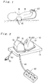
- Fig.1 is a side view of the massaging apparatus of the present invention illustrating the use thereof.
- Fig.2 is a perspective view of the massaging apparatus.
- Fig.3 is a front view, partially in cross-section, of the massaging apparatus shown in Fig.2.
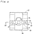
- Fig.4 is a cross-sectional view along the line IV-IV shown in Fig.5.
- Fig.5 is a top plan view of the massaging mechanism.
- Fig.6 is a side view of the massaging mechanism.
- Fig.7 is a cross-sectional view of the boss in the massaging mechanism.
- Fig.8 is a top plan view of the boss and the cam follower.
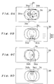
- Figs.9A-9D are top plan views of the boss and the cam follower to illustrate the locus of the support axle.
- Fig.10 is a perspective view of the pressing member.
- Figs.11A-11D are perspective views of the various pressing bumps.
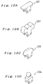
- Figs.12A-12D and Figs.13A-13B are perspective views of the various pressing members.
- Fig.14 is a top plan view of the controller.
- Fig.15 is a plan view of the massaging apparatus with parts broken away to show the base parts.
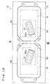
- Fig.16 is a top plan view of the massaging apparatus according to the second embodiment.
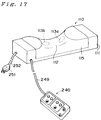
- Fig.17 is a perspective view of the massaging apparatus according to the third embodiment.
- Fig.18 is a front view, partially in cross-section, of the massaging apparatus shown in Fig.17.
- Fig.19 is a cross-sectional view along the line XIX-XIX shown in Fig.20.
- Fig.20 is a top plan view of the massaging mechanism.
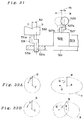
- Fig.21 is a side view of the massaging mechanism.
- Fig.22 is a plan view of the crank member of the massaging mechanism.
- Figs.23A-23B are plan views of two different cam members.
- Figs.24A-24D are top plan views of the cam member and the cam follower to illustrate the locus of the support axle.
- Fig.25 is a plan view of the controller.
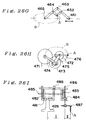
- Figs.26A-26I are front views of various elliptical mechanisms.
- Fig.27 is a perspective view of the massaging apparatus according to an another embodiment.
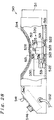
- Fig.28 is a front view, partially in cross-section, of the massaging apparatus.
- Fig.29 is a plan cross-sectional view of the reciprocating members.
- Fig.30 is a side cross-sectional view along the line XXX-XXX shown in Fig.29.
- Fig.31 is a partial front view of the massaging mechanism.
- Figs.32A-32B are diagrams to illustrate the loci of the pressing member.
- Fig.33 is a front view of the controller.
- Figs.34A-34B are front views of two different pressing members.
- Fig.35 is a front view of another massaging mechanism
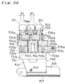
- Fig.36 is a cross-sectional view of a different massaging mechanism.
- Fig.37 is a perspective view of a different massaging apparatus.
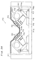
- Fig.38 is a cross-sectional view of the massaging apparatus.
- Fig.39 is a cross-sectional view along the line A-A shown in Fig.40.
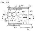
- Fig.40 is a top plan view of the massaging mechanism.
- Fig.41 is a side view of the massaging mechanism.
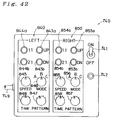
- Fig.42 is a plan view of the controller.
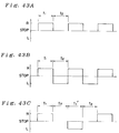
- Figs.43A-43B are graphs to show various drive pattern.
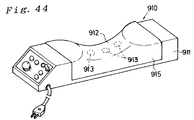
- Fig.44 is a perspective view of a different massaging apparatus.
- Fig.45 is a cross-sectional view of the massaging apparatus.
- Fig.46 is a front view to show how to use the massaging apparatuses.
- the massaging apparatus 10 is used to massage a neck portion N of a patient (human body) M. It comprises a support body 11 and a pair of massaging mechanisms 20,20 mounted on the support body 11 symmetrically.
- Each the massaging mechanism 20 has a pressing member 22 with a plurality of pressing bumps 21 and a mechanism cover 13 which covers the massaging mechanism 20. Since the right and left massaging mechanisms 20,20 have symmetrical structures, either one of the massaging mechanism 20 is described hereinafter.
- a massaging opening 13a is formed on a slant top surface of the mechanism cover 13. Though the massaging mechanism 20 is covered by the mechanism cover 13 on the support body 11, the top portion of the pressing member 22 is protruded through the massaging opening 13a.
- a cloth cover 15 is attached inside the mechanism cover 13 covering the massaging opening 13a, and accordingly the protruded portion of the pressing member 22 and the pressing bumps 21 are covered by the cloth cover 15.
- the massaging mechanism 20 is in detail described hereinafter further referring Figs. 4-6.
- the massaging mechanism 20 basically comprises a base 27 and a rotational driving device 30 swingably mounted on the base 27.
- the base 27 has a U-shape configuration with a pair of side plates 27a,27b extending vertically.
- a cam follower 39 is provided in the opening portion of the base 27 bridging the side plates 27a,27b.
- the cam follower 39 engages with a cylindrical boss (or a cam member) 34 to move the rotational driving device 30 swingably and reciprocatingly.
- the rotational driving device 30 comprises a drive motor 31, a support frame 32, a motor support member 33, the boss 34 and a pair of crank members 35.
- the support frame 32 has a U-shape construction in which the motor support member 33 is mounted.
- a pair of first swing axle support members 36 are mounted on the bottom lower surface of the support frame 32.
- a second swing axle support member 28 is mounted on the bottom upper surface of the base 27.
- a swing axle 23 is mounted through holes formed on the first and second swing axle support members 36,28 to swingably mount the support frame 32 on the base 27.
- the drive motor assembly 31 is mounted on the motor support member 33.
- a rotational axle 31a of the drive motor assembly 31 extends upward through a hole 33a formed in the motor support member 33.
- the drive motor assembly 31 comprises an electric motor 31c and a speed reduction gear device 31b having the rotational axle 31a.
- the rotational speed of the electric motor 31c can be controlled by a controller 40 (which will be described later) to drive the rotational axle at a desirable speed and torque.
- the cylindrical boss 34 is tightly fitted to the rotational axle 31a.
- a support axle 34a is formed on the upper surface of the boss 34 as shown in Fig.7.
- a axle insertion hole 34b is formed on the bottom surface of the boss 34.
- the center axis "X1" of the axle insertion hole 34b is eccentric from the center axis "X2" of the cylindrical boss 34 by a distance “R2”.
- the center axis "X3" of the support axle 34a is eccentric from the center axis "X1" of the axle insertion hole 34b by a distance "R1" as shown in Fig.7.
- a pressing member support 24 on which the pressing member 22 is mounted is supported by the cylindrical boss 34. As shown in Fig.4, a support hole 24a is formed on the central bottom surface of the pressing member support 24 in which the support axle 34a is loosely inserted. Two more support holes 24b,24b are also formed on the pressing member support 24 in which upper support axles 35a,35a of the crank member 35 are loosely inserted.
- a lower support axle 35b formed on the bottom portion of the crank member 35 is loosely inserted into a support hole 33d to support the pressing member support 24 via the crank member 35.
- the center axis "X4" of the lower support axle 35b is eccentric from the center axis "X3" of the upper support axle 35a by a distance "R1" as shown in Fig.6.
- the cylindrical boss 34 roles as a disc cam as shown in Fig.8. When the drive motor assembly 31 is driven, the cylindrical boss 34 rotates around the axis "X1".
- a substantially rectangular opening 39b is formed in the cam follower 39.
- the cylindrical boss 34 is inserted into the opening 39b and an outer peripheral surface 34c of the cylindrical boss 34 comes in contact with side contact surfaces 39a of the opening 39b.
- the cylindrical boss 34 and the cam follower 39 are made of plastic materials having a low coefficient of friction and a high wear resistance (for example, polyacetal resin) to allow a smooth rotation of the cylindrical boss 34 keeping in contact with the side surfaces 39a of the cam follower 39.
- the rotational driving device 30 on which the cylindrical boss 34 is mounted is swingably supported by the base 27 on which the cam follower 39 is mounted, the rotational driving device 30 is swung back and forth as shown by an arrow A in Fig.4 when the boss 34 is rotated. Namely, as shown by chain lines in Fig.8, the rotational driving device 30 is moved reciprocatingly with an amplitude of "R2" in each side.
- the relative motions of the cam follower 39 with respect to the rotational driving device 30 is shown in Fig.8, assuming that the rotational driving device 30 is held stationary, though the rotational driving devece 30 is actually moved reciprocatively with respect to the fixed cam follower 39.
- the pressing member support 24 Since the pressing member support 24 is rotated around the axis "X1" with a radius of "R1" by the drive motor 31, the pressing member 22 mounted on the pressing member support 24 is also rotated around the axis "X1". Accordingly, as a result of a combination of the rotational motion and the reciprocating swing motion, the pressing member 22 is moved so as to describe an ellipse locus.
- the outer peripheral surface 34c of the boss 34 is kept in contact with the side contact surfaces 39a in the cam follower 39.
- the boss 34 is rotated around the axle insertion hole 34b in the direction shown by an arrow I (counter-clockwise direction) as shown in Fig.9A, the contact surface (the outer peripheral surface 34c) is pushed by the side contact surfaces 39a of the cam follower. Since the cam follower 39 is fixedly mounted on the base 27, the support axle 34a and the axle insertion hole 34b is moved downward as shown by an arrow II.
- the pressing member support 24 and the pressing member 22 mounted thereon are also moved along the ellipse locus. If the distance "R1" and “R2" are varied, the shape of the ellipse locus can be changed.
- the shape of the ellipse locus can be changed. Further, if the location of the axle insertion hole 34b is varied, the shape of the ellipse locus can also be changed.
- the moving locus of the pressing member 22 can be changed.
- the pressing bumps 21 and the pressing member 22 are made of plastic materials having a low coefficient of friction and a high wear resistance.
- the pressing member 22 is formed so as to suitably fit with the massaging portion (e.g. neck portion N of a patient), and the three pressing bumps 21 are formed on the upper surface of the pressing member 22 as shown in Fig.10.
- the pressing bump 21 respectively has a pressing portion 21a and a support pole 21b. It is attachably mounted on the pressing member 22 by tightly inserting the support pole 21b into the hole 22b.
- the pressing member with the pressing bumps 21 is mounted on the pressing member support 24 by screws 23. It is mounted on the pressing member support 24 so as to cover a mounting portion 24c, and then is fastened by the screws 23 inserted into thread holes 24d through holes 22a.
- the pressing bumps can be formed as shown in Figs.11A-11D. Further, the pressing member and the pressing bumps can be made in one united body as shown in Figs.12A-12D and in Figs.13A-13B.
- the pressing member 22 is projecting outward through the massaging opening 13a. Therefore, when the pressing member 22 is moved transversely so as to describe the ellipse locus, the neck portion N of the patient M placed on the support body 11 as shown in Fig.l is massaged by the pressing member 22 (and the pressing bumps 21). Since the pressing member 22 and the pressing bumps 21 are made of plastic material with a low coefficient of friction, they can be moved smoothly against the cloth cover 15.
- the electric motor 31c is driven by an electric power supplied through an electric wire 52 and a plug 51 plugged into an outlet.
- the operation of the electric motor 31c is controlled by a controller 40.
- the controller 40 comprises a remote control unit separately located from the support body 11 as shown in Fig.2 and Fig.l4.
- the controller 40 is connected by a control wire 49 with the electric motor 31c in the support body 11.
- the controller 40 comprises a main switch 41, an operation indicating lamp 42, a left controlling unit 140 and a right controlling unit 150.
- the main switch controls the electric power supply. When it is turned on, the electric power is supplied to the electric motor 31c through the electric wire 52 to drive the motor 31c. When it is turned on, the operation indicating lamp 42 is simultaneously turned on.
- the left and right controlling units 140,150 are respectively used to operationally control the left and right massaging mechanisms 20. Since the left and the right controlling units 140,150 have the same construction with each other, only the left unit 140 is described here.
- the left controlling unit 140 comprises rotation change buttons 143a,143b and a speed control knob 145.
- the rotation change buttons 143a,143b are used to change the rotational direction of the electric motor 31c.
- the electric motor 31c is rotated so as to rotate the pressing member 22 counterclockwise.
- the electric motor 31c is rotated so as to rotate the pressing member 22 clockwise.
- the speed control knob 145 is used to control the rotational speed of the electric motor 31c. The further it is turned clockwise, the faster the electric motor 31c rotates to rotates the pressing member 22 faster.
- buttons and the speed change knobs are included in the controller 40, they are not always needed. A controller without these buttons and knobs can be used. Further, switches or buttons for continuously or intermittently operating the massaging mechanism can be included in the controller.
- the massaging mechanism 20 as constructed above is swingably connected to a base plate 16, which is mounted on the support body 11, via pins 18 as shown in Fig.3. It can be fixedly mounted by means of support poles 17.
- One end of the support pole 17 is connected to the base plate 16 by a pin 16a and the other end of the support pole 17 is connected to the base 27 by a screw 19. Since a slot 17a is formed on the support pole 17, the fixing location by the screw 19 can be adjusted so as to adjust the mounting angle of the massaging mechanism 20.
- the massaging mechanism 20 is mounted on the support body 11 through the base plate 16 so as to be able to adjust horizontal location of the mechanism 20 with respect to the support body 11.
- a plurality of slots 14a-14d are formed on the upper surface of the support body 11 and a plurality of slots 16b-16d are formed on the base plate 16 as shown in Fig.15.
- the base plate 16 by which the massaging mechanism 20 is supported is fixedly mounted on the support body 11 by means of screws 12 inserted through both the slots 14a-14d and 16b-16d so as to allow the horizontal adjustment.
- the mounting angle of the massaging mechanism can be adjusted by the screw 19 and the horizontal mounting location can be adjusted by the screws 12.
- a massaging apparatus 10' according to a second embodiment of the present invention is shown in Fig.16.
- a pair of mechanism covers 63 is symmetrically mounted on the support body 11 in parallel.
- the rotational driving devices 30 and the base plates 16 are also symmetrically mounted on the support body 11 in parallel inside the covers 63.
- the massaging opening 63a is formed aslant to put the pressing member 22 aslant as shown in Fig.16.
- the massaging apparatus 110 comprises a rectangular box type support body 111 with a curved recess 112 on which the neck portion N will be placed.
- the top surface of the support body 111 including the curved recess 112 is covered by a cloth cover 115.
- a right and a left massaging openings 113a,113b are formed on the curved recess 112.
- a pair of massaging mechanisms 120 are symmetrically placed in the support body 111.
- a plurality of pressing members 121 are included in the massaging mechanism 120 and are placed on the upper portion of the mechanism 120. They partially project outward through the massaging opening 113a,113b.
- the massaging mechanism 120 includes a base 127 and a rotational driving device 130 which is swingably mounted on the base 127.
- the base 127 integrally includes a cam follower support 127a which obliquely extends upward.
- a cam follower 139 is fixed to the cam follower support 127a with which a cam 136 will come in contact.
- the rotational driving device 130 comprises an electric motor 131, a support frame 132, a motor support 133, a boss 134, a crank member 135 and the cam 136.
- the support frame 132 has a U-shaped construction in which the motor support 133 is fixedly mounted.
- a swing axle 123 is placed penetrating the base 127 and the support frame 132, thereby the support frame 132 being swingably supported by the base 127.
- the electric motor 131 is mounted on the motor support 133.
- a rotational axle 131a of the motor 131 extends upward.
- the boss 134 is fixedly attached to the rotational axle 131a and is extended upward through a hole 133a formed in the motor support 133.
- a support axle 134a is formed on the upper surface of the boss 134.
- the center axis of the support axle 134a is eccentric from the center axis of the rotational axle 131a by a distance "R1".
- the support axle 134a is loosely fitted into a support hole 124a of a pressing member support 124. Another two support holes 124b,124c are also formed in the pressing member support 124. An upper support axle 135a formed on the upper surface of the crank member 135 is loosely fitted into the support hole 124b, and an upper support axle 136a formed on the upper surface of the cam 136 is also loosely fitted into the support hole 124c.
- a lower support axle 135b is formed at the center of the bottom surface of the crank member 135.
- the lower support axle 135b is loosely fitted into a support hole 133d formed in the motor support 133.
- the center axis of the upper support axle 135a is eccentric from the center axis of the lower support axle 135b by a distance "R1".
- the cam 136 has an egg-shape configuration to compose a plate cam as shown in Fig.23A.
- a lower support axle 136b is formed at the center of the bottom surface of the cam 136.
- the lower support axle 136b is loosely fitted into a support hole 133b formed in the motor support 133.
- the center axis of the upper support axle 136a is also eccentric from the center axis of the lower support axle 136b by a distance "R1".
- a tension spring 137 is placed between the cam follower support 127a and the motor support 133 so as to pull the massaging mechanism 120 toward the cam follower support 127a. Accordingly, the outer peripheral surface of the cam 136 is kept in contact with a contact surface 139a of the cam follower 139.
- the pressing member support 124 executes a circular motion with a radius "R1" and the pressing members 121 also execute a circular motion respectively.
- the radius "R1" of the circular motion depends on the location of the upper support axles 134a,135a,136a. As shown in Fig.22, for example three holes 134a, 134a',134a'' and 135a,135a',135a'' can be formed on the upper surface of the boss 134 and the crank member 135. Similar three holes 136a,136a',136a'' can also be formed on the upper surface thereof. If the upper support axle 134a,135a,136a are detachable, they can be selectively inserted in either of the holes to adjust the radius "R1".
- the pressing member 121 Since the circular motion and the reciprocating motion of the pressing member 121 is simultaneously executed by the rotational driving device 130, the pressing member 121 is moved so as to describe an ellipse locus.
- the cam 136 is kept in contact with the contact surface 139a of the cam follower 139 as shown in Fig.24A because of the tensile force "I" by the spring 137.
- the cam 136 is rotated around the lower support axle 136b clockwise as shown by an arrow "II"
- the cam 136 is clockwisely rotated while being kept in contact with the cam follower 139 to move the lower support axle right with respect to the cam follower 139 as shown by an arrow "III”.
- the upper support axle 136a is rotated along a circle with a radius "R1" moving right. Consequently, the upper support axle 136a is moved so as to describe an ellipse locus as shown in Figs.24A-24D.
- the pressing member support 124 and the pressing members 121 is also moved along the same size ellipse locus.
- the shape of the ellipse can be varied by changing the outer peripheral configuration of the cam 136.
- an ellipse configuration cam or a circular configuration cam 136' with an eccentric axis as shown in Fig.23B can be used instead of the cam 136 as shown in Fig.23A.
- the pressing member 121 is made of elastic material (such as rubber) or plastic.
- the pressing member 121 is mounted on a movable axle 122 which is vertically movable against the pressing member support 124.
- the pressing member 121 and the movable axle 122 is pushed upward by a spring 123.
- a vertical position adjusting mechanism to adjust the vertical position of the pressing member 121 (and the movable axle 122) can be included in the pressing member support 124.
- Vertical position adjusting button 343a,343b to control the operation of the vertical position adjusting mechanism are included in a controller 240 which will be described later.
- the upper portion of the pressing members 121 are projecting upward through the massaging opening 113.
- the pressing members 121 are moved so as to describe the ellipse locus, the neck portion N of the patient M placed on the curved recess 112 is massaged by the pressing members 121.
- the massaging opening 113 is formed at a place where a specific location for effectively relieving stiffness faces.
- the electric motor 131 is driven by an electric power supplied through an electric wire 252 and a plug 251 plugged into an outlet. The operation of the electric motor 131 is controlled by the controller 240.
- the controller 240 comprises a remote control unit separately located from the support body 111 as shown in Fig.17.
- the controller 240 is connected by a control wire 249 with the electric motor 131.
- the controller 240 comprises a main switch 241, an operational indicating lamp 242,a left controlling unit 240 and a right controlling unit 250.
- the main switch 241 controls the electric power supply. When it is turned on, the electric power is supplied to the motor 131 through the electric wire 252 to drive the motor 131. When it is turned on, the operation indicating lamp 242 is simultaneously turned on.
- the left and right controlling units 340,350 are respectively used to operationally control the left and right massaging mechanisms 120. Since the left and the right controlling units 340,350 have the same construction with each other, only the left unit 340 is described here.
- the left controlling unit 340 comprises the vertical position adjusting buttons 343a,343b and a motor control knob 345.
- the vertical position adjusting buttons 343a,343b are used to adjust the vertical position (the amount of the vertical projection) of the pressing member 121 and the movable axle 122.
- the up-button 343a is pushed down, the pressing member 121 is moved upward.
- the down-button 343b is pushed down, the pressing member 121 is moved downward.
- the motor control knob 345 is used to control the rotational speed and direction of the electric motor 131. When it is turned right from a neutral position (the position shown in Fig.25), the motor 131 is rotated clockwise. When turned left, the motor 131 is rotated counter-clockwise. The further it is turned right or left, the faster the motor 131 rotates.
- the massaging mechanism 120 is pivotally mounted to the base plate 116 by a pin 118.
- the mounting angle of the massaging mechanism 120 can be adjusted by a support pole 117.
- the massaging mechanism 120 is mounted on the bottom plate llla through the base plate 116 so as to allow a horizontal adjustment of location.
- the horizontal location can be adjusted by the same manner as shown in Fig.15.
- the pressing member is moved along an ellipse locus by combining a circular motion and a reciprocating motion.
- the present invention is not limited to such a mechanism. Any different mechanism to move the pressing member so as to describe an ellipse locus can be used in the present invention.
- an elliptic trammel mechanism comprising two perpendicular grooves 403,404, two sliders 401,402 slidably placed in the grooves 403,403 and an arm 405 pivotally connected to the sliders 401,402 can be used.
- the tip end "A" of the arm 405 can describe an ellipse locus "a".
- the pressing member will be mounted on the tip end A of the arm 405.
- An ellipse-crank mechanism as shown in Fig.26B can be used. It comprises crank members 411,412 and slider 413. When the crank member 411 is rotated around one end thereof, the slider connecting point A will describe an ellipse locus "a".
- a similar ellipse-crank mechanism comprising link members 421-424 as shown in Fig.26C can also be used.
- a scotch-yoke mechanism shown in Fig.26D can be used. It comprises a stationary gear 431, a planetary gear 432 and a yoke 436 with a slide axle 435.
- the planetary gear 432 has a slide pin A eccentrically located form its axis. When the planetary gear 432 is rotated around the stationary gear 431, the slide pin A describe an ellipse locus "a".
- An elliptic mechanism having a stationary internal gear 441 and a planetary external gear 442 as shown in Fig.26E can also be used.
- a tip end A of arm 443 describe an ellipse locus "a".
- FIG.26F Another elliptic mechanism having an ellipse cam 452 with an ellipse groove 452a, and crank members 451,453 as shown in Fig.26F can be used.
- An ellipsograph mechanism having four link members pivotally connected at the points 461-465 as shown in Fig.26G can be used.
- the end point 461 is slidably moved along a straight line with respect to the fixed point 465, the point "A" describe an ellipse locus "a".
- the mechanism comprises three gears 471,472,473, two link members 474,475 and an arm member 476.
- the center gear 472 meshes the other gears 471 and 473, and the gear 471 is stationary held against rotation.
- the arm member 476 rotates with the gear 473.
- a mechanism as shown in Fig.26I can also be used. It includes two pairs of bevel gears 481,482 and 483,484, and two axles 485,486.
- the bevel gear 481 is stationary held against rotation.
- an arm member 487 is attached. When the frame 488 is rotated, the point A at the tip end of the arm member 487 describe an ellipse locus.
- the massaging apparatus 510 comprises rectangular box type support body 511 with a curved recess 512 on which a specific portion (such as a neck portion) of a patient will be placed.
- the top surface of the support body including the curved recess 512 is covered by a cloth cover 514.
- a massaging opening 513 is formed on the curved recess 512.
- a massaging mechanism 520 is placed inside the support body 511.
- a pressing member 528 placed on the upper portion of the mechanism 520 is partially projecting outward through the massaging opening 513.
- the massaging mechanism 520 includes a reciprocating member 521 which is provided in the support body 511 so as to move back and forth along a pair of guide rails 515. As shown in detail in Figs.29 and 30, the reciprocating member 521 comprises four vertical guide rollers 522 and four horizontal guide rollers 523 to allow a smooth reciprocating motion of the reciprocating member 521.
- An electric motor 525 and a speed reduction device 526 are mounted on the reciprocating member 521.
- a crank-shaped first rotational axle 527 is extended upward from the speed reduction device 526.
- a spherical pressing member 528 is rotatively mounted on the top end of the first rotational axle 527.
- the first rotational axle 527 includes a base portion 527a which is rotative around an axis "A" and a tip portion 527b having a vertical axis "B".
- the axis "B” is eccentric from the axis "A” by a distance "R1".
- a reciprocating drive mechanism 530 having a crank-shaped second rotational axle 531 is provided on the front side of the reciprocating member 521.
- the drive mechanism 530 comprises an electric motor and a speed reduction device to rotate the second axle 531 around a base portion 531a of the axle 531.
- a slot 521b is formed in the reciprocating member 521.
- a tip portion 531b of the second rotational axle 531 is loosely inserted into the slot 521b.
- An axis "C" of the base portion 531a is eccentric from an axis "D" of the tip portion 531b by a distance "R2".
- the axis "D" of the second rotational axle 531 is rotated around the axis "C” as shown by an arrow “P” in Fig.32A.
- the axis "B” of the first rotation axle 527 is rotated around the axis "A” as shown by an arrow “Q”. Consequently, the axis "A” is moved right as shown by an arrow “R” and rotated as shown by the arrow Q.
- the resultant moving locus of the axis "B” is an ellipse as shown by a chain line "a".
- the upper portion of the pressing member 528 is projecting outward through the massaging opening 513.
- the pressing member 528 is moved transversely so as to describe the locus of ellipse or figure "8"
- the neck portion of the patient placed on the support body 511 is massaged by the pressing member 528.
- the massaging opening 528 is formed at a place where a specific location of the body for effectively relieving stiffness faces, the specific location is massaged by the pressing member 528 which is moved along the locus of either an ellipse or a figure "8".
- the speed reduction device 526 has an additional mechanism to move the first rotational axle 527 up and down, whereby the amount of outward projection of the pressing member 528 through the massaging opening 513 being adjusted.
- the electric motor 525 is driven by an electric power supplied through an electric wire 552 and a plug 551 plugged into an outlet.
- the operation of the electric motor 525 is controlled by a controller 540.
- the controller 540 comprises a main switch 541, an operation indicating lamp 542, projection adjusting buttons 543a,543b, speed ratio selection buttons 544a,544b, a speed control knob 545 and a mode selection knob 546 as shown in Fig.33.
- the main switch 541 controls the electric power supply. When it is turned on, the operation indication lamp 542 is simultaneously turned on.
- the speed ratio selection buttons 544a,544b are used to determine the speed ratio of the first and the second rotational axles 527,531.
- first selection button 544a When the first selection button 544a is pushed, both the first and second rotational axle 527,531 rotate at the same speed to move the pressing member 528 along the ellipse locus.
- second selection button 544b When the second selection button 544b is pushed, the first rotational axle 527 is rotated twice as fast as the second rotational axle 531 to move the pressing member 528 along the locus of figure "8".
- the rotational speed of the first and second rotational axles 527,531 can be adjusted by the speed control knob 545.
- Either A-mode, B-mode or C-mode can be selected by the mode selection knob 546.
- A-mode only the first rotational axle 527 is rotated to move the pressing member 528 along a circular locus.
- B-mode both the first and the second rotational axles 527,531 are rotated to move the pressing member along the locus of the ellipse or the figure "8".
- C-mode only the second rotational axle 531 is rotated to move the pressing member 528 back and forth reciprocatingly.
- the pressing member 528 has a ball-like configuration.
- a pressing member 561 having a cylindrical configuration with a spherical top as shown in Fig.34A can be used.
- the pressing member 561 is rotatively mounted on a support 562 which is threaded onto a thread portion 563a of a rotational axle 563. Accordingly, the vertical position of the support 562 can be adjusted by the threading adjustment to adjust the amount of the projection of the pressing member 561 through the massaging opening 513.
- the support 562 can be fixed by a fixing nut 562a.
- a spherical pressing member 565 eccentrically mounted on the straight rotational axle 566 as shown in Fig.34B can also used.
- the spherical center line B is eccentric from the axis A of the axle 566 by a distance "R1".
- FIG.35 A fifth embodiment according to the present invention is shown in Fig.35.
- two first rotational axles 571 is rotatively mounted on a speed reduction device 526'.
- a support plate 572 having three pressing members 573 is supported by the first rotational axles 571.
- the pressing members 573 are rotatively mounted on the support plate 572 respectively.
- the support plate 572 is moved along the same circular locus as that of the upper portion of the first rotational axles 571. Consequently, all the pressing members 571 can be moved along the locus of ellipse or figure "8".
- a massaging mechanism 620 as shown in Fig.36 can be used.
- the massaging mechanism 620 comprises a rotational drive motor 625 which is pivotally mounted around a pivot axle 625a on the support body 611 through a support arm 622. It further comprises a reciprocation drive motor 630 fixedly mounted on the support body 611.
- a swing plate 621 is mounted on the rotational drive motor 625, and two crank-shape sub-rotational axles 624 are rotatively mounted on the swing plate 621 through rotation support members 623.
- a support plate 629 is supported by the sub-rotational axles 624.
- a first rotational axle 627 of the rotational drive motor 625 also has a crank-shape.
- the upper end of the first rotational axle 627 is rotatively connected to a fixed axle 628c through a bearing 627c.
- a pressing member 628 is rotatively mounted on the upper end of the fixed axle 628c.
- the pressing member 628 is pushed upward by a spring 628d.
- the pressing member 628 includes a metal body 628a and a rubber cover 628b.
- Two more fixed axles 628c are respectively mounted on the upper ends of the fixed axles 628c, and two more pressing members 628 are mounted on the upper end of the axles 628c.
- One end of a reciprocation arm 632 is connected to the reciprocation drive motor 630 at a point eccentric from a drive axle 631 of the motor 630.
- the other end of the arm 632 is connected to the swing plate 621.
- the swing plate 621 is swung back and forth to move the pressing members 628 back and forth reciprocatingly. If the rotational drive motor 625 is simultaneously driven, the pressing members 628 can be moved so as to describe the locus of an ellipse or a figure "8".
- a massaging apparatus 710 according to a different embodiment of the present invention is shown in Fig.37.
- the massaging apparatus 710 comprises a rectangular box type support body 711 with a curved recess 712 on which a neck portion of a patient will be placed.
- the top surface of the support body 711 is covered by a cloth cover 715.
- a pair of massaging openings 713a,713b are formed on the curved recess 712.
- a pair of massaging mechanisms 720 are symmetrically placed in the support body 711. Pressing members 721 provided on the upper portion of the mechanism 720 are partially projecting outward through the massaging openings 713a,713b.
- the massaging mechanism 720 comprises a base 727, a side plate 726 fixedly connected with the base 727 and a rotational drive device 730 which is swingably connected to the side plate 726 via a pivot axle 723.
- a reciprocation drive motor 728 is mounted on the side plate 726.
- the rotational drive device 730 comprises a rotational drive motor 731, a support frame 732, a motor support 733, a boss 734 and a pair of first crank members 735.
- the support frame 732 has a U-shaped construction in which the motor support 733 is fixedly mounted.
- the pivot axle 723 is placed penetrating the side plates 726 to swingably support the support frame 732 by the side plate 726.
- the rotational drive motor 731 is mounted on the motor support 733.
- a rotational axle 731a of the motor 731 extends upward through a hole 733a of the motor support 733.
- the motor support 733 has a side projecting portion 733b having a slot 733c.
- the boss 734 is fixedly attached to the rotational axle 731a.
- An upper support axle 734a is formed on the upper surface of the boss 734.
- the axis of the upper support axle 734a is eccentric from the axis of the rotational axle 731a by a distance "R1".
- the upper support axle 734a is loosely fitted into a support hole 724a of a pressing member support 724. Another two support holes 724b are also formed in the pressing member support 724. Upper support axles 735a of the first crank members 735 are loosely fitted into the support holes 724b.
- Lower support axles 735b are formed on the bottom surface of the first crank members 735.
- the lower support axles 735b are respectively eccentric from the upper support axles 735a by a distance "R1" and are loosely inserted into support holes 733d of the motor support 733.
- the pressing member support 724 is moved along a circular locus to move the pressing member along the same locus.
- a swing axle 729a of a second crank member 729 is loosely inserted into the slot 733c.
- the second crank member 729 is fixedly connected with an output axle of the reciprocation drive motor 728.
- the axis of the swing axle 729a is eccentric from the axis of the output axle of the motor 728 by a distance "R2".
- the pressing members 721 can be moved to as to describe a locus of ellipse or figure "8" as described above.
- the motors 731,728 are independently controlled their speeds to allow the motion along either an ellipse locus or a figure "8" locus. Further, the rotational direction of the motor 731 is independently controllable.
- a controller 740 to control the motors is provided.
- the controller 740 comprises a remote control unit separately located from the support body 711 as shown in Fig.42.
- the controller 740 is connected with the motors 731,728 through a control wire 749.
- the controller 740 comprises a main switch 741, an operation indicating lamp 742, a left controlling unit 840 and a right controlling unit 850.
- the main switch 741 controls the electric power supply. When it is turned on, the operation indicating lamp 742 is simultaneously turned on. Since the left and the right controlling units 840,850 have the same construction, only the left unit 840 is described here.
- the left controlling unit 840 comprises projection adjusting buttons 843a,843b, speed ratio selection buttons 844a,844b, a speed control knob 845, a mode selection knob 846, a pattern selection knob 847 and a timer knob 848.
- the projection adjusting buttons 843a,843b are used to adjust the amount of outward projection of the pressing member 721.
- the up-button 843a When the up-button 843a is pushed, the pressing member 721 is projecting outwardly.
- the down-button 843b When the down-button 843b is pushed, it is retracted.
- the speed ratio selection buttons 844a,844b are used to determine the speed ratio of the rotational drive motor 731 and the reciprocation drive motor 728.
- first button 844a When the first button 844a is pushed, both the motors 731,728 are rotated at the same speeds to move the pressing member 721 along the ellipse locus.
- second button 844b When the second button 844b is pushed, the speed ratio becomes 2:1 to move the pressing member 721 along the locus of figure "8".
- the speed control knob 845 is used to control the rotational speeds of both the motors 731,728 and the rotational direction of the rotational drive motor 731. When it is turned right from a neutral position, both the motors 731,728 are rotated clockwise. When it is turned left from the neutral position, the rotational drive motor 731 is rotated counter-clockwise while the reciprocation drive motor 728 is rotated clockwise. The further it is turned right or left from the neutral position, the faster the motors 731,728 rotate.
- Either A-mode, B-mode or C-mode can be selected by the mode selection knob 846.
- A-mode only the rotational drive motor 731 is driven to move the pressing members 721 along a circular locus.
- B-mode both the motors 731,728 are driven to move the pressing members 721 along the locus of ellipse or figure "8".
- C-mode only the reciprocation drive motor 728 is driven to move the pressing members 721 back and forth reciprocatingly.
- Either a continuous drive pattern, an intermittent drive pattern, a reversible drive pattern or an intermittent-reversible drive pattern can be selected by the pattern selection knob 847.
- both the motors 731,728 are driven continuously.
- both the motors 731,728 are driven for tl time (for example, for ten seconds) and then they are halted for t2 time (for example, for another ten seconds) as shown in Fig.43A.
- the rotational drive motor 731 is driven clockwise for tl time and then it is driven counter-clockwise for t2 time as shown in Fig.43B while the reciprocation drive motor 728 is kept driving.
- the intermittent-reversible drive pattern is selected, the combination of the intermittent drive and the reversible drive is achieved as shown in Fig.43C.
- the above time t1,t2 can be adjusted by the timer knob 848 in the intermittent drive or the intermittent-reversible drive pattern.
- the driving time in the reversible drive pattern can also be adjusted by the timer knob 848.
- the massaging apparatus 910 comprises a rectangular support body 911 with a curved recess 912. The top surface thereof is covered by a cloth cover 915.
- Three massaging openings 913 are formed on the curved recess 912.
- Three massaging mechanisms 920 are placed inside the support body 911 so that each pressing member 924 partially project outward through the massaging opening 913.
- the massaging mechanism 920 comprises an electric motor 921, a speed reducing device 922 to reduce the motor speed, a rotational axle 923 which is rotated by the motor 921 transmitted through the speed reducing device 922, and the pressing member 924 mounted on the tip end of the rotational axle 923.
- the rotational axle 923 has a crank-shape.
- the upper axis "A” of the axle 923 is eccentric from the lower axis "B" of the axle 923 by a distance "R”.
- the pressing member 924 (having the axis "B") is moved transversely along a circular locus with a radius "R”.
- the massaging apparatuses are used to massage a neck portion of a patient.
- the massaging apparatus according to the present invention can be constructed to massage other portion of the human body.
- a massaging chair C having a neck massager 150 and a waist massager 155 can be used.
Landscapes
- Health & Medical Sciences (AREA)
- Epidemiology (AREA)
- Pain & Pain Management (AREA)
- Physical Education & Sports Medicine (AREA)
- Rehabilitation Therapy (AREA)
- Life Sciences & Earth Sciences (AREA)
- Animal Behavior & Ethology (AREA)
- General Health & Medical Sciences (AREA)
- Public Health (AREA)
- Veterinary Medicine (AREA)
- Dermatology (AREA)
- Massaging Devices (AREA)
- Finger-Pressure Massage (AREA)
- Percussion Or Vibration Massage (AREA)
Applications Claiming Priority (10)
| Application Number | Priority Date | Filing Date | Title |
|---|---|---|---|
| JP264388/93 | 1993-09-28 | ||
| JP26438893A JPH084610B2 (ja) | 1993-09-28 | 1993-09-28 | マッサージ装置 |
| JP304739/93 | 1993-11-10 | ||
| JP5304739A JP2525723B2 (ja) | 1993-11-10 | 1993-11-10 | マッサ―ジ装置 |
| JP72755/94 | 1994-03-17 | ||
| JP6072755A JPH07255802A (ja) | 1994-03-17 | 1994-03-17 | マッサージ装置 |
| JP74169/94 | 1994-03-18 | ||
| JP7416994 | 1994-03-18 | ||
| JP133604/94 | 1994-04-24 | ||
| JP6133604A JPH07303679A (ja) | 1994-03-18 | 1994-04-24 | マッサージ装置 |
Publications (1)
| Publication Number | Publication Date |
|---|---|
| EP0645132A1 true EP0645132A1 (de) | 1995-03-29 |
Family
ID=27524406
Family Applications (1)
| Application Number | Title | Priority Date | Filing Date |
|---|---|---|---|
| EP94307062A Withdrawn EP0645132A1 (de) | 1993-09-28 | 1994-09-27 | Massagegerät |
Country Status (6)
| Country | Link |
|---|---|
| US (1) | US5695451A (de) |
| EP (1) | EP0645132A1 (de) |
| KR (1) | KR0128983B1 (de) |
| CN (1) | CN1102977A (de) |
| AU (1) | AU680287B2 (de) |
| CA (1) | CA2132994A1 (de) |
Cited By (2)
| Publication number | Priority date | Publication date | Assignee | Title |
|---|---|---|---|---|
| US20220117833A1 (en) * | 2019-02-07 | 2022-04-21 | Svetozar Grbic | Portable massage appliance |
| US20240000609A1 (en) * | 2022-06-29 | 2024-01-04 | Twenty Twenty Therapeutics Llc | System, method, and apparatus for massaging the eyelid |
Families Citing this family (20)
| Publication number | Priority date | Publication date | Assignee | Title |
|---|---|---|---|---|
| US5868688A (en) * | 1996-01-22 | 1999-02-09 | Yonitech Laboratories Ltd. | Foot massaging appliance |
| US5984883A (en) * | 1997-04-08 | 1999-11-16 | Elnar; Joseph G. | Neck massager for use in spas |
| USD414560S (en) | 1998-10-08 | 1999-09-28 | Kabushiki Kaisha Fuji Iryoki | Portable massage device |
| DE20021882U1 (de) * | 2000-12-29 | 2001-03-22 | Huang, Chin-Hsin, Changhua | Übungsgerät |
| SE520599C2 (sv) * | 2002-05-06 | 2003-07-29 | Fredrik Lagercrantz | Anordning för massage och tryckbehandling av hud och kroppsdelar |
| NZ580228A (en) * | 2007-03-09 | 2012-06-29 | Fka Distributing Dba Homedics | Body massager with a biasing member for urging an upper torso massager into contact with a user |
| US20090118652A1 (en) * | 2007-10-03 | 2009-05-07 | Vito James Carlucci | Neck massaging device |
| US20090209890A1 (en) * | 2008-02-20 | 2009-08-20 | Hiroshi Nakamura | Massaging apparatus |
| KR100966084B1 (ko) * | 2008-02-25 | 2010-06-28 | 한정민 | 경추용 교정장치 |
| US8702588B2 (en) * | 2008-04-28 | 2014-04-22 | Michael Trzecieski | Play flow control apparatus and method for controlling a play flow of a sensual consumer product |
| WO2009146351A1 (en) * | 2008-05-28 | 2009-12-03 | Fka Distributing Co. D/B/A Homedics, Inc. | Body massagers |
| US20130012845A1 (en) * | 2011-07-07 | 2013-01-10 | Joseph Swoyer | Knee joint mobilizer |
| CN102579221B (zh) * | 2012-01-18 | 2013-09-11 | 深圳市倍轻松科技股份有限公司 | 颈部按摩器 |
| US20140188019A1 (en) * | 2012-12-28 | 2014-07-03 | Shenzhen Breo Technology Co., Ltd. | Neck massager |
| JP7231182B2 (ja) * | 2018-07-23 | 2023-03-01 | ファミリーイナダ株式会社 | 施療ユニットおよび当該施療ユニットを用いたマッサージ機 |
| CN109125033B (zh) * | 2018-09-12 | 2020-09-22 | 东阳市天齐知识产权运营有限公司 | 一种智能化按摩装置 |
| US11730663B2 (en) * | 2019-08-11 | 2023-08-22 | Stephanus Van Der Merwe | Neck and upper back massage device |
| CN113197755B (zh) * | 2021-05-06 | 2022-04-01 | 上海大学 | 一种智能三维运动按摩机械装置 |
| KR20250041761A (ko) * | 2023-09-19 | 2025-03-26 | 주식회사 세라젬 | 폭 방향 가압 위치 조절이 가능한 링크부가 구비된 마사지 장치 |
| KR102883593B1 (ko) * | 2025-04-17 | 2025-11-10 | 김병학 | 냉찜질이 가능한 졸음방지기구 |
Citations (7)
| Publication number | Priority date | Publication date | Assignee | Title |
|---|---|---|---|---|
| GB531088A (en) * | 1939-06-27 | 1940-12-30 | William George Moore | Improvements in vibratory massage or like devices |
| US2914065A (en) * | 1956-08-17 | 1959-11-24 | William L Cory | Scalp massaging device |
| US4061137A (en) * | 1976-08-24 | 1977-12-06 | Clayton Sandt | Kinesitherapeutic bed structure |
| DE2713438A1 (de) * | 1977-03-26 | 1978-09-28 | Walter Schake | Bandscheibeneinrenkungs- und reflexzonenbehandlungs-einrichtung |
| CH639268A5 (en) * | 1979-08-31 | 1983-11-15 | Peter Michel | Body massaging device |
| AT380395B (de) * | 1984-11-05 | 1986-05-12 | Gerhard Ing Hengl | Massagegeraet fuer die unteren extremitaeten |
| DE9208487U1 (de) * | 1992-06-25 | 1992-09-24 | Pan, Chang Shyong, Lu-Chou Hsiang, Taipeh | Taillentrainer |
Family Cites Families (10)
| Publication number | Priority date | Publication date | Assignee | Title |
|---|---|---|---|---|
| US3103925A (en) * | 1961-05-01 | 1963-09-17 | Edwin M Vogt | Vibratory massage device |
| US3699952A (en) * | 1971-02-03 | 1972-10-24 | Sunbeam Corp | Skin treating appliance |
| US3984101A (en) * | 1975-02-18 | 1976-10-05 | Alfonso Garza | Self-force resister type exercising device |
| US5065743A (en) * | 1988-06-20 | 1991-11-19 | Sutherland W Don | Kneader |
| SU1692578A1 (ru) * | 1989-06-30 | 1991-11-23 | Научно-Исследовательский Институт Гигиены Труда И Профессиональных Заболеваний Амн Ссср | Массажное кресло |
| US5203321A (en) * | 1990-12-11 | 1993-04-20 | Sutter Corporation | Passive anatomic ankle-foot exerciser |
| US5137015A (en) * | 1991-02-22 | 1992-08-11 | James Anglehart | Apparatus for supporting and moving a person's head |
| US5233973A (en) * | 1992-03-23 | 1993-08-10 | General Motors Corporation | Support structure for humans and massaging mechanism therefor |
| US5356369A (en) * | 1992-06-11 | 1994-10-18 | Kabushiki Kaisha Japan Health | Portable vibration finger pressure massager |
| JP3291332B2 (ja) * | 1992-10-19 | 2002-06-10 | 三洋電機株式会社 | マッサージ機 |
-
1994
- 1994-09-23 US US08/311,558 patent/US5695451A/en not_active Expired - Fee Related
- 1994-09-27 CA CA002132994A patent/CA2132994A1/en not_active Abandoned
- 1994-09-27 KR KR1019940024365A patent/KR0128983B1/ko not_active Expired - Fee Related
- 1994-09-27 EP EP94307062A patent/EP0645132A1/de not_active Withdrawn
- 1994-09-27 AU AU74229/94A patent/AU680287B2/en not_active Ceased
- 1994-09-28 CN CN94116461A patent/CN1102977A/zh active Pending
Patent Citations (7)
| Publication number | Priority date | Publication date | Assignee | Title |
|---|---|---|---|---|
| GB531088A (en) * | 1939-06-27 | 1940-12-30 | William George Moore | Improvements in vibratory massage or like devices |
| US2914065A (en) * | 1956-08-17 | 1959-11-24 | William L Cory | Scalp massaging device |
| US4061137A (en) * | 1976-08-24 | 1977-12-06 | Clayton Sandt | Kinesitherapeutic bed structure |
| DE2713438A1 (de) * | 1977-03-26 | 1978-09-28 | Walter Schake | Bandscheibeneinrenkungs- und reflexzonenbehandlungs-einrichtung |
| CH639268A5 (en) * | 1979-08-31 | 1983-11-15 | Peter Michel | Body massaging device |
| AT380395B (de) * | 1984-11-05 | 1986-05-12 | Gerhard Ing Hengl | Massagegeraet fuer die unteren extremitaeten |
| DE9208487U1 (de) * | 1992-06-25 | 1992-09-24 | Pan, Chang Shyong, Lu-Chou Hsiang, Taipeh | Taillentrainer |
Cited By (2)
| Publication number | Priority date | Publication date | Assignee | Title |
|---|---|---|---|---|
| US20220117833A1 (en) * | 2019-02-07 | 2022-04-21 | Svetozar Grbic | Portable massage appliance |
| US20240000609A1 (en) * | 2022-06-29 | 2024-01-04 | Twenty Twenty Therapeutics Llc | System, method, and apparatus for massaging the eyelid |
Also Published As
| Publication number | Publication date |
|---|---|
| CN1102977A (zh) | 1995-05-31 |
| AU7422994A (en) | 1995-04-13 |
| CA2132994A1 (en) | 1995-03-29 |
| KR950007815A (ko) | 1995-04-15 |
| AU680287B2 (en) | 1997-07-24 |
| KR0128983B1 (ko) | 1998-04-04 |
| US5695451A (en) | 1997-12-09 |
Similar Documents
| Publication | Publication Date | Title |
|---|---|---|
| US5695451A (en) | Massaging apparatus | |
| KR100236139B1 (ko) | 마사지기 | |
| EP1386559B1 (de) | Handgehaltene Enthaarungsvorrichtung | |
| US6432072B1 (en) | Hand held percussive massager with adjustable nodes | |
| EP1736129A2 (de) | Massagevorrichtung | |
| KR20250069559A (ko) | 연속으로 진폭이 가변되는 왕복 구동 기구 및 마사지 건 | |
| CN111096888B (zh) | 按摩机 | |
| JP2003290307A (ja) | 性器マッサージ器具保持駆動装置 | |
| JP2021090681A (ja) | マッサージ装置 | |
| CN219875350U (zh) | 无级变幅往复驱动机构及筋膜枪 | |
| JP2525723B2 (ja) | マッサ―ジ装置 | |
| KR102021670B1 (ko) | 안마장치 | |
| US4759304A (en) | Device for control and regulation of upper feed mechanism of overlock sewing machine | |
| JPH0753621Y2 (ja) | マッサ−ジ装置 | |
| US3064603A (en) | Speed-changing cam device for zigzag sewing machines | |
| US3633527A (en) | Toy sewing machine capable of switching between zigzag stitch forming and straight stitch forming operations | |
| JPH1176336A (ja) | 按摩機 | |
| CN223731739U (zh) | 一种滑动按摩器的控制机构 | |
| JPH0653138B2 (ja) | マッサージ機 | |
| JPH07255802A (ja) | マッサージ装置 | |
| JPH07255800A (ja) | マッサージ装置 | |
| JP2501503B2 (ja) | マッサ−ジ装置 | |
| KR102730250B1 (ko) | 종아리용 전동 안마기 | |
| CN222444730U (zh) | 按摩组件及按摩设备 | |
| JP2709907B2 (ja) | マッサージ機 |
Legal Events
| Date | Code | Title | Description |
|---|---|---|---|
| PUAI | Public reference made under article 153(3) epc to a published international application that has entered the european phase |
Free format text: ORIGINAL CODE: 0009012 |
|
| AK | Designated contracting states |
Kind code of ref document: A1 Designated state(s): DE ES FR GB IT |
|
| 17P | Request for examination filed |
Effective date: 19950922 |
|
| RAP1 | Party data changed (applicant data changed or rights of an application transferred) |
Owner name: KAWAKAMI, TETSUHIRO |
|
| RIN1 | Information on inventor provided before grant (corrected) |
Inventor name: KAWAKAMI, HISATOMI |
|
| 17Q | First examination report despatched |
Effective date: 19981124 |
|
| STAA | Information on the status of an ep patent application or granted ep patent |
Free format text: STATUS: THE APPLICATION HAS BEEN WITHDRAWN |
|
| 18W | Application withdrawn |
Withdrawal date: 20000325 |