EP0646833A1 - Emballage pour bobines de bande photosensible - Google Patents
Emballage pour bobines de bande photosensible Download PDFInfo
- Publication number
- EP0646833A1 EP0646833A1 EP94420255A EP94420255A EP0646833A1 EP 0646833 A1 EP0646833 A1 EP 0646833A1 EP 94420255 A EP94420255 A EP 94420255A EP 94420255 A EP94420255 A EP 94420255A EP 0646833 A1 EP0646833 A1 EP 0646833A1
- Authority
- EP
- European Patent Office
- Prior art keywords
- housing
- shaft
- rolls
- web
- package
- Prior art date
- Legal status (The legal status is an assumption and is not a legal conclusion. Google has not performed a legal analysis and makes no representation as to the accuracy of the status listed.)
- Granted
Links
- 238000000034 method Methods 0.000 claims abstract description 14
- 238000004891 communication Methods 0.000 claims abstract description 4
- 239000000463 material Substances 0.000 claims description 7
- 238000003780 insertion Methods 0.000 claims description 2
- 230000037431 insertion Effects 0.000 claims description 2
- 125000006850 spacer group Chemical group 0.000 description 8
- 238000010276 construction Methods 0.000 description 3
- 229910000831 Steel Inorganic materials 0.000 description 2
- XAGFODPZIPBFFR-UHFFFAOYSA-N aluminium Chemical compound [Al] XAGFODPZIPBFFR-UHFFFAOYSA-N 0.000 description 2
- 229910052782 aluminium Inorganic materials 0.000 description 2
- 238000004140 cleaning Methods 0.000 description 2
- 238000009833 condensation Methods 0.000 description 2
- 230000005494 condensation Effects 0.000 description 2
- 238000004519 manufacturing process Methods 0.000 description 2
- 239000010959 steel Substances 0.000 description 2
- 239000002390 adhesive tape Substances 0.000 description 1
- 230000002411 adverse Effects 0.000 description 1
- 230000004888 barrier function Effects 0.000 description 1
- 150000001875 compounds Chemical class 0.000 description 1
- 239000011152 fibreglass Substances 0.000 description 1
- 239000006260 foam Substances 0.000 description 1
- 238000009434 installation Methods 0.000 description 1
- 238000004806 packaging method and process Methods 0.000 description 1
- 230000002085 persistent effect Effects 0.000 description 1
- 229920001084 poly(chloroprene) Polymers 0.000 description 1
- 238000003466 welding Methods 0.000 description 1
Images




Classifications
-
- B—PERFORMING OPERATIONS; TRANSPORTING
- B65—CONVEYING; PACKING; STORING; HANDLING THIN OR FILAMENTARY MATERIAL
- B65H—HANDLING THIN OR FILAMENTARY MATERIAL, e.g. SHEETS, WEBS, CABLES
- B65H16/00—Unwinding, paying-out webs
- B65H16/005—Dispensers, i.e. machines for unwinding only parts of web roll
-
- B—PERFORMING OPERATIONS; TRANSPORTING
- B65—CONVEYING; PACKING; STORING; HANDLING THIN OR FILAMENTARY MATERIAL
- B65H—HANDLING THIN OR FILAMENTARY MATERIAL, e.g. SHEETS, WEBS, CABLES
- B65H16/00—Unwinding, paying-out webs
- B65H16/02—Supporting web roll
- B65H16/021—Multiple web roll supports
-
- B—PERFORMING OPERATIONS; TRANSPORTING
- B65—CONVEYING; PACKING; STORING; HANDLING THIN OR FILAMENTARY MATERIAL
- B65H—HANDLING THIN OR FILAMENTARY MATERIAL, e.g. SHEETS, WEBS, CABLES
- B65H19/00—Changing the web roll
- B65H19/10—Changing the web roll in unwinding mechanisms or in connection with unwinding operations
- B65H19/12—Lifting, transporting, or inserting the web roll; Removing empty core
- B65H19/126—Lifting, transporting, or inserting the web roll; Removing empty core with both-ends supporting arrangements
-
- G—PHYSICS
- G03—PHOTOGRAPHY; CINEMATOGRAPHY; ANALOGOUS TECHNIQUES USING WAVES OTHER THAN OPTICAL WAVES; ELECTROGRAPHY; HOLOGRAPHY
- G03B—APPARATUS OR ARRANGEMENTS FOR TAKING PHOTOGRAPHS OR FOR PROJECTING OR VIEWING THEM; APPARATUS OR ARRANGEMENTS EMPLOYING ANALOGOUS TECHNIQUES USING WAVES OTHER THAN OPTICAL WAVES; ACCESSORIES THEREFOR
- G03B27/00—Photographic printing apparatus
- G03B27/32—Projection printing apparatus, e.g. enlarger, copying camera
- G03B27/52—Details
- G03B27/58—Baseboards, masking frames, or other holders for the sensitive material
- G03B27/587—Handling photosensitive webs
- G03B27/588—Supply rolls; Cutting arrangements
-
- B—PERFORMING OPERATIONS; TRANSPORTING
- B65—CONVEYING; PACKING; STORING; HANDLING THIN OR FILAMENTARY MATERIAL
- B65H—HANDLING THIN OR FILAMENTARY MATERIAL, e.g. SHEETS, WEBS, CABLES
- B65H2405/00—Parts for holding the handled material
- B65H2405/40—Holders, supports for rolls
- B65H2405/42—Supports for rolls fully removable from the handling machine
- B65H2405/422—Trolley, cart, i.e. support movable on floor
-
- B—PERFORMING OPERATIONS; TRANSPORTING
- B65—CONVEYING; PACKING; STORING; HANDLING THIN OR FILAMENTARY MATERIAL
- B65H—HANDLING THIN OR FILAMENTARY MATERIAL, e.g. SHEETS, WEBS, CABLES
- B65H2701/00—Handled material; Storage means
- B65H2701/10—Handled articles or webs
- B65H2701/17—Nature of material
- B65H2701/171—Physical features of handled article or web
- B65H2701/1719—Photosensitive, e.g. exposure, photographic or phosphor
Definitions
- the invention relates to the packaging of rolls of web. More particularly, the invention concerns packages and a method for storing and delivering multiple rolls of photosensitive web having very great lengths.
- Photoprinters adapted to receive rolls of photosensitive web directly from an external supply generally require mateable packages capable of providing several fairly lengthy rolls of photosensitive web to the system for continuous high volume printing.
- An existing package system described in U.S. patent Application, Serial No. 952,897, filed November 20, 1992, and based on priority French application No. 9000007375 filed June 8, 1990 can accommodate eight 6000 foot rolls of photosensitive web at a time.
- the existing package is designed to be end loaded from a slitter by the photographic paper manufacturer, closed and then shipped loaded to the photofinisher. When the photographic paper supply is exhausted, the photofinisher must return the empty package to the photographic paper manufacturer for reloading.
- Shortcomings of the existing package therefore include its inability to accommodate more lengthy rolls of photosensitive web as well as a greater number of rolls of web.
- photoprinter system uptime is at least partially adversely affected by the limited capacity of the existing package.
- another problem with the existing package is that it cannot be conveniently loaded by the photofinisher and, therefore, must be returned to the photographic paper manufacturer for reloading.
- the existing package must be of rugged construction.
- the prior art package is limited to a substantially cylindrical shape to minimize condensation damage to the photosensitive rolls of web resulting from differing temperatures during shipment.
- the cylindrical shaped existing package provides a path for condensation to roll down the side walls of the package and not drip on the photosensitive web.
- conventional packages for rolls of photosensitive web are limited in their capacity to hold large rolls of web (that is, very much greater than 6000 feet).
- the existing package rests on a pallet at the photofinisher's for the convenience of the shipping process, it cannot be easily maneuvered by the photofinisher without the aid of a lift device, such as a fork lift.
- a package for storing and delivering rolls of photosensitive web to a photoprinter comprising a housing having an interior compartment.
- the interior compartment includes a bottom wall and upstanding first and second opposed end walls and sidewalls.
- the first and second end walls and sidewalls define a top edge surrounding an opening exposing the interior compartment.
- a shaft is positionable in the interior compartment through the opening for supporting at least one roll of photosensitive web.
- the shaft is removably mounted to the first and second opposite end walls.
- a top wall having an openable member for accessing the interior compartment, is removably mounted to the top edge of the housing in a light-lock relationship.
- a continuous channel in the top edge of the housing for receiving a lip portion of the top wall provides a light lock.
- slot-like openings are provided in communication with the interior compartment, each of the slot-like opening providing a light-tight path for delivering a strip of photosensitive web from the interior compartment.
- a method for loading photosensitive rolls of web into the package described above comprises removing the top wall from the housing and then the shaft from the interior compartment. The photosensitive web rolls are then mounted on the shaft and the shaft having the rolls thereon is inserted into the interior compartment. The top wall is mounted onto the housing in a light lock relationship.
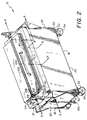
- package 10 constructed in accordance with the principles of the invention.
- package 10 comprises housing 12 , preferably made of steel or other rigid material such as fiber glass or aluminum, having an interior compartment 14 .
- Housing 12 has first and second sidewalls 16,18 , first and second end walls 20,22 , a bottom wall 26 , and a removably mounted top wall 24 , the top wall 24 being described in greater details below.
- first and second end walls 20,22 and sidewalls 16,18 define a top edge 25 of housing 12 surrounding an opening 27 . Opening 27 provides means to access the interior compartment 14 for inserting or removing rolls of web or for cleaning the interior compartment 14 .
- the top edge 25 has a continuous channel 28 therein for receiving a continuous lip portion 23 of the top wall 24 in an interlocking relationship, as described further below.
- package 10 is a rectanguloid having a length (1) of about 70 inches (177.8 cm), a height (h) of about 48 inches (121.9 cm), and a width (w) of about 40 inches (101.6 cm).
- a shaft 32 positionable in the interior compartment 14 , is removably mounted to the end walls 20,22 .
- Shaft 32 described further below, provides support for one or more rolls of photosensitive web (A) wound on a core, such as photographic paper.
- interior compartment 14 and shaft 32 can accomodate rolls of web having a diameter of about 36 inches (91.44cm) or about 9000 ft. of web.
- the bottom wall 26 supporting upstanding first and second sidewalls 16,18 and first and second end walls 20,22 , is substantially flat and comprises a brake 208 and a caster 34 mounted for rotation on each of the exterior corners 36,38,40,42 thereof.
- Brake 208 has a rubber-like stopper that engages the floor when urged by paddle 209 and is used to prevent movement of the package 10 when not in use; and, it can also be used when the package 10 is positioned at one of several predetermined photographic paper delivery positions, as described below. According to Fig.
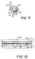
- mounting plates 50 affixed to the bottom wall 26 by, for instance, bolts 53 , or they may be welded, provide a rigid and level surface to which to mount the caster support member 52 .
- Caster support member 52 comprising spaced opposing first and second wall portions 56,58 , is attached to the mounting plate 50 by screws or any suitable means.
- Casters 34 are rotatably mounted on rod members 54 .
- Rod members 54 are supported in first and second wall portions 56,58 of caster support members 52 .
- Hub members 62 are mounted on either end of the rod member 54 to ensure that the casters 34 do not separate from the rod members 54 .
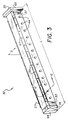
- shaft 32 made preferably of steel or other suitable rigid material, such as aluminum, is a substantially smooth elongated surface having a length (L) of about 60 inches (162.6 cm) and a diameter (D) of about 6 inches (15.2 cm) so as to receive the rolls of web mounted thereon.
- L length
- D diameter
- one end portion 33 of shaft 32 has attached thereto a substantially V-shaped mounting member 64 .
- the opposite end portion 35 of shaft 32 has attached thereto a substantially square-shaped mounting member 68 .
- welding is the preferred means of attaching mounting members 64,68 to the end portions 33,35 , respectively, of shaft 32 , other suitable means, such as screws, may be used.
- Mounting members 64,68 provide means to mount shaft 32 onto end walls 20,22 in interior compartment 14 , as described below.
- Shaft 32 is removed from interior compartment 14 of the housing 12 by first removing the top wall 24 and then securely grasping both end portions of the shaft 32 while raising the shaft 32 upwardly through opening 27 until it clears the top edge 25 .
- each end wall 20,22 has a grooved, correspondingly aligned, plate-like member 60 or 66 affixed thereto conformed to receive an end portion 33,35 of shaft 32 .
- plate-like member 60 has a substantially V-shaped groove slightly larger than corresponding mounting member 64 of shaft 32 .
- opposed second end wall 24 is provided with plate-like member 66 having a substantially square shaped groove slightly larger than corresponding mounting member 68 of shaft 32 .
- slightly oversized grooves in plate-like members 60,66 enable the shaft 32 to fit easily but securely in the grooves thereby facilitating shaft 32 removal and installation.
- Skilled artisans will appreciate that there are alternative ways within the contemplation of the invention for supporting shaft 32 , such as, providing the groove portions described above in the opposing end walls 20,22 .
- top wall 24 has an openable member 100 connected by a hinge 103 , or similar attachment means, to the top rearward portion 101 of top wall 24 .
- Openable member 100 includes a handle 104 mounted preferably to a top forward portion 105 of member 100 and, a pair of gas springs 106 , one each being cooperatively mounted to top wall 24 and to openable member 100 .
- the gas springs 106 counter-balance the weight of the openable member 100 for easily raising and lowering the openable member 100 to an open and then closed position.
- the operator can access the interior compartment 14 to, for instance, check the supply of rolls, clean the interior, clear a feed through problem and so forth.
- openable member 100 Since the rolls of photosensitive web are sensitive to light, openable member 100 should only be accessed when the housing is in a dark room environment (except for cleaning).
- the openable member 100 can be held in the open position by simply raising the member 100 .
- the openable member 100 can be raised when the latches 102 are disengaged.
- slot like openings 80 are mounted on a front edge portion 110 of openable member 100 .
- package 10 is provided with a plurality of contiguous light-tight slot-like openings 80 which allow strips of web 70 or photographic paper to be pulled out of the interior compartment 14 of housing 12 .
- twelve contiguous slot-like openings 80 are positioned in the front edge portion 110 of the top wall 24 .
- slot-like openings 80 may alternatively be positioned, for instance, in sidewall 18 (not shown).
- slot like openings 80 are defined by corresponding upper and lower half-slot portions 82,84 .
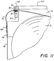
- Upper and lower half-slot portions 82,84 form a light-locked path for photographic paper strips exiting the interior compartment 14 ( Figure 11).
- the upper half-slot portion 82 which delineates a portion of the slot-like opening 80 , is attached to openable member 100 . Owing to this, the rolls of web (A) arranged on the shaft 32 are easily accessed by tilting open openable member 100 , as described in more details below. It is obvious that this operation is performed during the photographic paper loading process in a fully dark room, as indicated above, so as not to fog the photosensitive product.
- slot-like openings 80 in communication with interior compartment 14 , are opened to expose the rolls of web (A) by tilting upwardly the upper half-slot portion 82 using handle 104 .
- the openable member 100 With the openable member 100 in the open position, as shown in Fig. 8, a strip of web 70 is pulled from one of several rolls of web (A) and the strip 70 adhesively bonded to sidewall 18 of housing 12 (Fig. 11). This operation is repeated for all the rolls of web (A) set on the shaft 32 ; then, the openable member 100 is closed thereby bringing upper half-slot portion 82 and lower half slot-like member 84 into a tightly closed relations forming slot-like openings 80 .
- web strip 70 is shown emerging through a slot-like opening 80 and fastened onto sidewall 24 by means of an adhesive tape 88 .
- a clip (not shown) or similar attachment means may also be used for securing the web strip 70 .
- the hinge 103 and the upper half-slot portion 82 which delineate the slot-like openings 80 are fitted with light locking material, described below, similar to that described French patent application 9001858 already cited.
- a foam-like material layer 81 Fig. 11
- a jersey foam compound sold by Etableaus Gergonne in Oyonnax, France is applied to the upper and lower half slot portions 82,84 .
- other materials, such as felt may also be used to improve tightness between the upper half-slot and lower half-slot portions 82,84 .
- a method for loading rolls of web (A) into package 10 includes first removing the top wall 24 from the housing 12 . Free access to the interior compartment 14 and the shaft 32 therein which supports the rolls of web (A) is provided in this manner. Practically any means for removing top wall 24 may be used although hoisting the top wall 24 away from the housing 12 is preferred.
- lift support members 112 comprising elongated slot portions 117 extending above the top surface of openable member 100 are welded to opposing ends 113,115 of top wall 24 .
- a hoist device (not shown), preferably including hooks for graspably engaging elongated slot portions 117 of lift support members 112 is used to remove and to mount top wall 24 .
- the rolls of photosensitive web (A) are then loaded onto the shaft 32 one at a time until the shaft 32 is at least partially loaded.
- the shaft 32 is loaded by inserting it into the rolls of web (A) when the rolls are placed in a horizontal position (not illustrated).
- spacers 44 are mounted along the shaft 32 at predetermined distances.
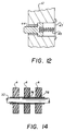
- a plurality of retractable pin-like members 44 comprising a spring member 45 biased against support plate 47 are mounted in shaft 32 .
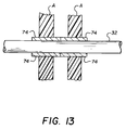
- the pin-like member 44 retracts and enables the roll of web (A) to locate to a preferred position along the shaft 32 between adjacent pin-like members 44 , as best seen in Fig. 13.
- the pin-like member 44 retracts and enables the roll of web (A) to locate to a preferred position along the shaft 32 between adjacent pin-like members 44 , as best seen in Fig. 13.
- oversized core spacers 74 that is, wherein the spacer width is greater than the width of the paper core
- an undersized paper core 76 that is, wherein the spacer width is less than the width of the paper core
- the diameter of the spacer must be less than the diameter of the paper core to ensure that unwinding of the last convolution of paper on the core is not impeded.
- one end of the shaft 32 is supported by a hoist or similar device and the free end is then inserted through prepackaged cores of photographic paper (not shown).
- the shaft 32 supporting one or more rolls of web (A) is then hoisted into position for insertion into the interior compartment 14 of the housing 12 .
- grooves 37 are provided on either end portion 33,35 of shaft 32 to receive J-hook members used in conjunction with the hoist for ensuring a stable and secure transportation of shaft 32 .
- Mounting members 64,68 of shaft 32 are then inserted into a locking relations with the corresponding V-shaped groove and square groove of plate-like members 60,66 attached to end walls 20,22 , as described previously.
- top wall 24 is then mounted onto the top edge 25 of housing 12 in a light-lock relations. Lip portion 23 of top wall 24 is carefully snugly inserted into the continuous channel 28 surrounding opening 27 .
- a compressible material layer 29 such as closed cell neoprene, is lined along the channel 28 thereby providing additional barrier against light leakage.
- the package 10 is preferably located in juxtaposition with a photoprinter (not shown) adapted to receive photographic paper from an external supply.
- a photoprinter (not shown) adapted to receive photographic paper from an external supply.
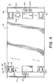
- handles 21 (Figs. 1,2,4, & 7) mounted to the exterior of either end wall 20,22 provide a convenient means to push or pull the package into position.
- package 10 is positionable along a predetermined path, such as a guide track 202 mounted to the floor.
- Guide track 202 comprises a continuous grooved portion 205 for receiving cam follower 201 affixed to and extending downwardly from the bottom portion 72 of end wall 20 of housing 12 .
- Guide track 202 enables the user to manipulate the location of package 10 relative to the photoprinter and it facilitates the photographic paper loading process.
- Retractable locating pin 204 extending downwardly from the bottom portion 72 of end wall 20 and adjacent to the cam follower 201 is insertable into one of a plurality of holes 203 , each hole 203 corresponding to a predetermined photographic paper delivery position.
- a photographic paper delivery position is defined by the alignment of a slot-like opening 80 with a utilization device, such as a buffer or photoprinter (not shown).
- a utilization device such as a buffer or photoprinter (not shown).
- the package 10 is then advanced to a preselected second roll delivery position along guide track 202 .
- the package 10 is guided by means of cam follower 201 moving along in groove portion 205 .
- Precise location of package 10 for photographic paper delivery is achieved by means of locating pin 204 and mateable hole 203 in track 202 .
- locating holes 203 in the track 202 are spaced to correspond to the spacing of the photographic webs on the shaft 32 .
- the process for locating the photographic webs for use by the photoprinter is as follows: after a photographic web has been consumed, the locating pin member 204 is retracted from the mateable hole 203 . The package 10 is then manually moved to the next locating pin member 204 location corresponding to the next preselected photographic paper delivery position and the locating pin member 204 is then inserted into the corresponding mateable hole 203 . This operation continues until all the rolls of web (A) supported by shaft 32 are consumed.
- an important advantage of the present invention is that it provides a package for photosensitive rolls of web (A) for photoprinters that is convenient to use, of simple construction, maneuverable, economical to manufacture, easily loaded by the photofinisher, and has greater capacity to contain more lengthy and greater number rolls of photosensitive web.
Landscapes
- Physics & Mathematics (AREA)
- General Physics & Mathematics (AREA)
- Packaging Of Machine Parts And Wound Products (AREA)
- Unwinding Webs (AREA)
- Packages (AREA)
Applications Claiming Priority (2)
| Application Number | Priority Date | Filing Date | Title |
|---|---|---|---|
| US08/129,889 US5390872A (en) | 1993-09-30 | 1993-09-30 | Package for rolls of photosensitive web |
| US129889 | 1993-09-30 |
Publications (2)
| Publication Number | Publication Date |
|---|---|
| EP0646833A1 true EP0646833A1 (fr) | 1995-04-05 |
| EP0646833B1 EP0646833B1 (fr) | 1998-11-18 |
Family
ID=22442069
Family Applications (1)
| Application Number | Title | Priority Date | Filing Date |
|---|---|---|---|
| EP94420255A Expired - Lifetime EP0646833B1 (fr) | 1993-09-30 | 1994-09-26 | Emballage pour bobines de bande photosensible |
Country Status (6)
| Country | Link |
|---|---|
| US (1) | US5390872A (fr) |
| EP (1) | EP0646833B1 (fr) |
| JP (1) | JPH07159935A (fr) |
| AU (1) | AU667647B2 (fr) |
| CA (1) | CA2130382C (fr) |
| DE (1) | DE69414676T2 (fr) |
Families Citing this family (5)
| Publication number | Priority date | Publication date | Assignee | Title |
|---|---|---|---|---|
| DE19535448C1 (de) * | 1995-09-23 | 1996-10-02 | Kodak Ag | Magazin für Filmpatronen |
| JP3255062B2 (ja) * | 1997-01-17 | 2002-02-12 | 松下電器産業株式会社 | 電子部品装着装置 |
| DE10014842A1 (de) * | 2000-03-24 | 2001-09-27 | Heidelberger Druckmasch Ag | Vorrichtung zum Lagern, Transportieren und Zuführen von flächigem Bedruckstoff für eine diesen verarbeitende Maschine |
| US20100163667A1 (en) * | 2008-12-28 | 2010-07-01 | Corey Dorais | Portable Cable and Wire Transporting Apparatus |
| GB2471685B (en) | 2009-07-08 | 2011-05-25 | Andrew Dean | Reel dispenser |
Citations (5)
| Publication number | Priority date | Publication date | Assignee | Title |
|---|---|---|---|---|
| US4111379A (en) * | 1976-04-13 | 1978-09-05 | Gretag Aktiengesellschaft | Cassette for strip material |
| EP0227436A2 (fr) * | 1985-12-20 | 1987-07-01 | Minnesota Mining And Manufacturing Company | Boîtier et volet anti-desserage étanche à la lumière |
| US5148215A (en) * | 1990-11-16 | 1992-09-15 | Brother Kogyo Kabushiki Kaisha | Magazine unit of image recording apparatus for accommodating image recording medium |
| FR2679532A1 (fr) * | 1991-07-22 | 1993-01-29 | Kodak Pathe | Emballage, a broche, collectif et reutilisable pour produit photosensible. |
| FR2679533A1 (fr) * | 1991-07-22 | 1993-01-29 | Kodak Pathe | Emballage, a multiple supports, collectif et reutilisable pour produit photosensible. |
Family Cites Families (18)
| Publication number | Priority date | Publication date | Assignee | Title |
|---|---|---|---|---|
| US3104847A (en) * | 1963-09-24 | Film supply magazine | ||
| US1268222A (en) * | 1918-01-28 | 1918-06-04 | Joseph F Dwyer | Device for dispensing tickets. |
| US1593781A (en) * | 1924-09-29 | 1926-07-27 | Guy W See | Reel |
| US2978155A (en) * | 1958-02-19 | 1961-04-04 | Kermit B Knutson | Tape dispenser |
| US3315910A (en) * | 1965-10-04 | 1967-04-25 | Eastman Kodak Co | Cartridge dispenser |
| US4024107A (en) * | 1975-05-12 | 1977-05-17 | General Electric Company | Method of separating a copper-amine catalyst from a polyphenylene ether reaction mixture |
| CH589554A5 (fr) * | 1975-07-29 | 1977-07-15 | Bobst Fils Sa J | |
| DE3375603D1 (en) * | 1983-12-12 | 1988-03-10 | Agfa Gevaert Nv | Light-tight cassette |
| EP0161569B1 (fr) * | 1984-05-09 | 1989-10-18 | Ferag AG | Dispositif pour enrouler et/ou dérouler des objets imprimés alimentés en continu de préférence en formation imbriquée |
| DE3662472D1 (en) * | 1985-07-30 | 1989-04-20 | Gretag Ag | Cassette for web-like photographic material |
| US4632326A (en) * | 1985-09-03 | 1986-12-30 | Emerson Electric Co. | Coil handling apparatus |
| DE3571232D1 (en) * | 1985-11-04 | 1989-08-03 | Agfa Gevaert Nv | Light-tight film reel package |
| US4714210A (en) * | 1986-06-23 | 1987-12-22 | E. I. Du Pont De Nemours And Company | Dispensing apparatus |
| JP2510570Y2 (ja) * | 1989-09-04 | 1996-09-11 | 富士写真フイルム株式会社 | ロ―ル状写真感光材料の集合包装体 |
| FR2663007A1 (fr) * | 1990-06-08 | 1991-12-13 | Kodak Pathe | Emballage de produits photographiques en bandes. |
| US5053795A (en) * | 1990-11-05 | 1991-10-01 | Minnesota Mining And Manufacturing Company | Reusable cartridge for storing and dispensing light sensitive web material |
| US5193759A (en) * | 1990-12-28 | 1993-03-16 | Eastman Kodak Company | Film or paper cassette |
| US5165542A (en) * | 1991-05-07 | 1992-11-24 | Minnesota Mining And Manufacturing Company | Reusable container for tape pancakes |
-
1993
- 1993-09-30 US US08/129,889 patent/US5390872A/en not_active Expired - Fee Related
-
1994
- 1994-08-18 CA CA002130382A patent/CA2130382C/fr not_active Expired - Fee Related
- 1994-09-20 JP JP6225156A patent/JPH07159935A/ja not_active Withdrawn
- 1994-09-26 EP EP94420255A patent/EP0646833B1/fr not_active Expired - Lifetime
- 1994-09-26 DE DE69414676T patent/DE69414676T2/de not_active Expired - Fee Related
- 1994-09-29 AU AU74368/94A patent/AU667647B2/en not_active Ceased
Patent Citations (5)
| Publication number | Priority date | Publication date | Assignee | Title |
|---|---|---|---|---|
| US4111379A (en) * | 1976-04-13 | 1978-09-05 | Gretag Aktiengesellschaft | Cassette for strip material |
| EP0227436A2 (fr) * | 1985-12-20 | 1987-07-01 | Minnesota Mining And Manufacturing Company | Boîtier et volet anti-desserage étanche à la lumière |
| US5148215A (en) * | 1990-11-16 | 1992-09-15 | Brother Kogyo Kabushiki Kaisha | Magazine unit of image recording apparatus for accommodating image recording medium |
| FR2679532A1 (fr) * | 1991-07-22 | 1993-01-29 | Kodak Pathe | Emballage, a broche, collectif et reutilisable pour produit photosensible. |
| FR2679533A1 (fr) * | 1991-07-22 | 1993-01-29 | Kodak Pathe | Emballage, a multiple supports, collectif et reutilisable pour produit photosensible. |
Also Published As
| Publication number | Publication date |
|---|---|
| CA2130382C (fr) | 1998-12-15 |
| US5390872A (en) | 1995-02-21 |
| JPH07159935A (ja) | 1995-06-23 |
| AU667647B2 (en) | 1996-03-28 |
| DE69414676T2 (de) | 1999-06-10 |
| CA2130382A1 (fr) | 1995-03-31 |
| AU7436894A (en) | 1995-05-04 |
| DE69414676D1 (de) | 1998-12-24 |
| EP0646833B1 (fr) | 1998-11-18 |
Similar Documents
| Publication | Publication Date | Title |
|---|---|---|
| EP0649806B1 (fr) | Appareil et procédé pour charger des rouleaux de bande dans un récipient | |
| US10689223B2 (en) | Cable reel and reel carrying caddy | |
| JPH05197048A (ja) | カセット用パレット | |
| EP0646833B1 (fr) | Emballage pour bobines de bande photosensible | |
| CA2125338A1 (fr) | Chariot pour la manutention de piles de journaux | |
| US5918395A (en) | Artwork display box | |
| EP0679524B1 (fr) | Boíte de stockage d'une cassette pour une imprimante thermique | |
| US5311232A (en) | Film magazine for feeding film developing machines and device for preparing said magazine | |
| JPS6090167A (ja) | テ−ブ・ケ−ス容器 | |
| JP4557510B2 (ja) | 画像形成装置の梱包装置 | |
| EP0811877B1 (fr) | Cassette et méthode pour charger à la lumière ambiante un paquet de feuilles photographiques | |
| JP3267437B2 (ja) | プリンタ装置 | |
| JP2949407B2 (ja) | 容器積載運搬用台車 | |
| EP0207237A1 (fr) | Système de stockage, transport et distribution de cassettes de bande magnétique | |
| JP3207141B2 (ja) | シートロール用の輸送コンテナ | |
| JP3473881B2 (ja) | 画像形成装置 | |
| JPH09309534A (ja) | 大形リール輸送用パレット | |
| JP2846201B2 (ja) | フイルム供給方法及びフイルム供給装置 | |
| JPH07319073A (ja) | フィルムカートリッジマガジン並びにフィルムカートリッジの取り扱いシステム及び取り扱い方法 | |
| JPH0615577Y2 (ja) | トイレットペーパーホルダー | |
| JP2546742Y2 (ja) | フイルム装填装置 | |
| JP2935416B2 (ja) | 大形リール輸送用パレット | |
| JPH0741713Y2 (ja) | ロール紙収容用ホルダー | |
| JPS59158755A (ja) | シ−ト収納積載装置 | |
| GB2326871A (en) | Carriers for transport of electronic circuits |
Legal Events
| Date | Code | Title | Description |
|---|---|---|---|
| PUAI | Public reference made under article 153(3) epc to a published international application that has entered the european phase |
Free format text: ORIGINAL CODE: 0009012 |
|
| AK | Designated contracting states |
Kind code of ref document: A1 Designated state(s): BE CH DE FR GB IT LI NL |
|
| 17P | Request for examination filed |
Effective date: 19950913 |
|
| 17Q | First examination report despatched |
Effective date: 19970515 |
|
| GRAG | Despatch of communication of intention to grant |
Free format text: ORIGINAL CODE: EPIDOS AGRA |
|
| GRAG | Despatch of communication of intention to grant |
Free format text: ORIGINAL CODE: EPIDOS AGRA |
|
| GRAH | Despatch of communication of intention to grant a patent |
Free format text: ORIGINAL CODE: EPIDOS IGRA |
|
| GRAH | Despatch of communication of intention to grant a patent |
Free format text: ORIGINAL CODE: EPIDOS IGRA |
|
| GRAA | (expected) grant |
Free format text: ORIGINAL CODE: 0009210 |
|
| AK | Designated contracting states |
Kind code of ref document: B1 Designated state(s): BE CH DE FR GB IT LI NL |
|
| REG | Reference to a national code |
Ref country code: CH Ref legal event code: EP |
|
| REF | Corresponds to: |
Ref document number: 69414676 Country of ref document: DE Date of ref document: 19981224 |
|
| ET | Fr: translation filed | ||
| REG | Reference to a national code |
Ref country code: CH Ref legal event code: NV Representative=s name: KIRKER & CIE SA |
|
| PLBE | No opposition filed within time limit |
Free format text: ORIGINAL CODE: 0009261 |
|
| STAA | Information on the status of an ep patent application or granted ep patent |
Free format text: STATUS: NO OPPOSITION FILED WITHIN TIME LIMIT |
|
| PG25 | Lapsed in a contracting state [announced via postgrant information from national office to epo] |
Ref country code: GB Free format text: LAPSE BECAUSE OF NON-PAYMENT OF DUE FEES Effective date: 19990926 |
|
| PG25 | Lapsed in a contracting state [announced via postgrant information from national office to epo] |
Ref country code: LI Free format text: LAPSE BECAUSE OF NON-PAYMENT OF DUE FEES Effective date: 19990930 Ref country code: CH Free format text: LAPSE BECAUSE OF NON-PAYMENT OF DUE FEES Effective date: 19990930 Ref country code: BE Free format text: LAPSE BECAUSE OF NON-PAYMENT OF DUE FEES Effective date: 19990930 |
|
| 26N | No opposition filed | ||
| BERE | Be: lapsed |
Owner name: EASTMAN KODAK CY Effective date: 19990930 |
|
| PG25 | Lapsed in a contracting state [announced via postgrant information from national office to epo] |
Ref country code: NL Free format text: LAPSE BECAUSE OF NON-PAYMENT OF DUE FEES Effective date: 20000401 |
|
| REG | Reference to a national code |
Ref country code: CH Ref legal event code: PL |
|
| GBPC | Gb: european patent ceased through non-payment of renewal fee |
Effective date: 19990926 |
|
| NLV4 | Nl: lapsed or anulled due to non-payment of the annual fee |
Effective date: 20000401 |
|
| PG25 | Lapsed in a contracting state [announced via postgrant information from national office to epo] |
Ref country code: DE Free format text: LAPSE BECAUSE OF NON-PAYMENT OF DUE FEES Effective date: 20000701 |
|
| PGFP | Annual fee paid to national office [announced via postgrant information from national office to epo] |
Ref country code: FR Payment date: 20010831 Year of fee payment: 8 |
|
| PG25 | Lapsed in a contracting state [announced via postgrant information from national office to epo] |
Ref country code: FR Free format text: LAPSE BECAUSE OF NON-PAYMENT OF DUE FEES Effective date: 20030603 |
|
| REG | Reference to a national code |
Ref country code: FR Ref legal event code: ST |
|
| PG25 | Lapsed in a contracting state [announced via postgrant information from national office to epo] |
Ref country code: IT Free format text: LAPSE BECAUSE OF NON-PAYMENT OF DUE FEES;WARNING: LAPSES OF ITALIAN PATENTS WITH EFFECTIVE DATE BEFORE 2007 MAY HAVE OCCURRED AT ANY TIME BEFORE 2007. THE CORRECT EFFECTIVE DATE MAY BE DIFFERENT FROM THE ONE RECORDED. Effective date: 20050926 |