EP0646994A2 - Connecteur à levier de verrouillage - Google Patents
Connecteur à levier de verrouillage Download PDFInfo
- Publication number
- EP0646994A2 EP0646994A2 EP94115462A EP94115462A EP0646994A2 EP 0646994 A2 EP0646994 A2 EP 0646994A2 EP 94115462 A EP94115462 A EP 94115462A EP 94115462 A EP94115462 A EP 94115462A EP 0646994 A2 EP0646994 A2 EP 0646994A2
- Authority
- EP
- European Patent Office
- Prior art keywords
- lever
- portions
- support shafts
- pair
- connector housing
- Prior art date
- Legal status (The legal status is an assumption and is not a legal conclusion. Google has not performed a legal analysis and makes no representation as to the accuracy of the status listed.)
- Granted
Links
Images


Classifications
-
- H—ELECTRICITY
- H01—ELECTRIC ELEMENTS
- H01R—ELECTRICALLY-CONDUCTIVE CONNECTIONS; STRUCTURAL ASSOCIATIONS OF A PLURALITY OF MUTUALLY-INSULATED ELECTRICAL CONNECTING ELEMENTS; COUPLING DEVICES; CURRENT COLLECTORS
- H01R13/00—Details of coupling devices of the kinds covered by groups H01R12/70 or H01R24/00 - H01R33/00
- H01R13/62—Means for facilitating engagement or disengagement of coupling parts or for holding them in engagement
- H01R13/629—Additional means for facilitating engagement or disengagement of coupling parts, e.g. aligning or guiding means, levers, gas pressure electrical locking indicators, manufacturing tolerances
- H01R13/62933—Comprising exclusively pivoting lever
- H01R13/62938—Pivoting lever comprising own camming means
-
- H—ELECTRICITY
- H01—ELECTRIC ELEMENTS
- H01R—ELECTRICALLY-CONDUCTIVE CONNECTIONS; STRUCTURAL ASSOCIATIONS OF A PLURALITY OF MUTUALLY-INSULATED ELECTRICAL CONNECTING ELEMENTS; COUPLING DEVICES; CURRENT COLLECTORS
- H01R13/00—Details of coupling devices of the kinds covered by groups H01R12/70 or H01R24/00 - H01R33/00
- H01R13/62—Means for facilitating engagement or disengagement of coupling parts or for holding them in engagement
- H01R13/629—Additional means for facilitating engagement or disengagement of coupling parts, e.g. aligning or guiding means, levers, gas pressure electrical locking indicators, manufacturing tolerances
- H01R13/62933—Comprising exclusively pivoting lever
- H01R13/62955—Pivoting lever comprising supplementary/additional locking means
Definitions
- the present invention relates to a lever support structure for a lever-type connector which can be connected by use of the leverage of a lever.
- the lever-type connector is advantageous in that the connection and removal thereof can be executed with a small force and, especially, it is often applied to a multipole connector which has 20 poles or more.
- the basic principle of the lever-type connector utilizes the leverage action of a lever and, as a structure for the lever-type connector, for example, there is known such a structure as shown in Fig. 7.
- a female connector housing 1 which stores therein a large number of female terminals (not shown)
- a male connector housing 2 which stores therein a large number of male terminals and includes a hood portion 2a for receiving the female connector housing 1.
- cam receive pins 3 are respectively provided on the right and left side wall portions of the female connector housing 1, on the right and left side walls of a hood portion 2a of the male connector housing 2, there are formed slits 4 respectively for receiving the cam receive pins 3.
- a U-shaped lever 5 is rotatably mounted to the male connector housing 2.
- a structure for mounting the lever 5 to the male connector housing 2 is arranged such that a pair of lever support shaft 2b are projected from the right and left wall portions of the male connector housing 2, two circular bearing holes 5a are respectively formed in the right and left side portions of the lever 5 and, as shown in Fig. 7, the lever support shaft 2b are inserted through the two bearing holes 5a of the lever 5, respectively.
- cam grooves 6 On the back surface of the lever 5, there are formed two cam grooves 6 which are respectively engageable with the cam receive pins 3.
- the cam grooves 6 are connected in communication with slits 4 when the lever 5 is held at such position as shown in Fig. 7. If the female connector housing 1 is inserted into the hood portion 2a of the male connector housing 2 and the lever 5 is rotated in a direction of an arrow shown in Fig. 7, then the cam grooves 6 of the lever 5 allows the cam receive pins 3 and thus the female connector housing 1 to advance deeply into the hood portion 2a of the male connector housing 2, which completes the connection between the male and female connectors.
- an insertion load is applied to the operation of the lever 5.
- the insertion load increases as the turn of the lever advances.
- the operation force necessary to push the operation portion 5b of the lever 5 is increased in opposition to the increase in the insertion load.
- the increased operation force causes the operation portion 5b of the lever 5 to be flexed in a recessed manner, so that the arms 5c of the lever 5 are respectively extended outwardly. If the arms 5c are extended outwardly too much, then the arms 5c can be removed out of the lever support shaft 2b.
- a lever-type connector in which, a U-shaped lever including a pair of cam portions is rotatably provided in one of connector housings of connectors to be connected to each other in such a manner that the lever straddles the connector housing, a pair of cam receive portions respectively engageable with the cam portions are provided in the other connector housing, and by rotating the lever reciprocatingly, the cam receive portion are shifted so as to connect or disconnect the two connectors to and from each other
- the lever-type connector comprising: a pair of lever support shafts provided on and projected from one of the one connector housing and the lever, a pair of bearing hole portions respectively formed in the other of the one connector housing and the lever and engageable with the lever support shafts; a pair of removal preventive portions formed in one of the lever support shafts and the bearing hole portions and projecting in the diameter direction of one of the lever support shafts and the bearing hole portions; and a pair of engaging surfaces respectively provided in the other of the lever support shafts and the bearing hole portions
- the lever when the lever is mounted on the connector housing, the lever is positioned at the disconnected position of the two connectors and then the removal preventive portions provided in one of the lever support shafts and the bearing hole portions are inserted from the notched portions of the engaging surfaces provided in the other of the lever support shafts and the bearing hole portions. And, when the lever is operated in order to connect the two connectors to each other, the lever is rotated from the disconnected position toward the connected position of the two connectors. In doing so, with the connection of the two connectors, the lever is given an operation force in opposition to an insertion load acting on the lever, so that the lever is flexed.
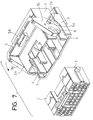
- a female connector housing 11 which stores therein female terminals (not shown)
- a male connector housing 12 which stores therein male terminals (not shown) and includes a hood portion 12a.
- the female connector housing 11 is formed in such a size that allows itself to be inserted into the hood 12a of the male connector housing 12 and includes on the right and left side portions thereof a pair of laterally projecting cam receive pins 13 which respectively correspond to cam receive portions provided in the male connector housing 12 (only one of the cam receive pins 13 is shown in Fig. 1).
- the male connector housing 12 is formed in a box member which is open at the front surface thereof and includes a pair of guide grooves 15 which are respectively formed on the right and left side portions thereof in such a manner that, when the female connector housing 11 is inserted, the cam receive pins 13 can be inserted into the guide grooves 15.
- a pair of lever support shafts 16 are projected sideways, on which a lever 17 is mounted by means of a support structure (which will be described later).
- the lever 17 is formed in a U-shaped member in which the ends of a pair of right and left arm portions 18 are connected to each other at an operation portion 20. Also, the lever 17 is mounted on the male connector housing 12 in such a manner that the two arm portions 18 respectively straddle the right and left side wall portions of the male connector housing 12. On the back sides (on the male connector housing 12 sides) of the two arm portions 18, there are formed cam grooves 22 corresponding to cam portions and, when the female connector housing 11 is inserted, the cam receive pins 13 are moved into the cam grooves 22 respectively. While the cam receive pins 13 are being inserted in the cam grooves 22, if the lever 17 is rotated from the disconnected position shown in Fig.
- the cam grooves 22 move the female connector housing 11 to the inside of the hood portion 12a of the male connector housing 12 by means of the cam operation thereof to thereby connect the male and female terminals with each other and thus connect the two connectors with each other.
- each of the lever support shafts 16 is formed in a cylindrical shape which is provided on and projected from the male connector housing 12 and includes in the leading end portion thereof a projection 30 which is projected out radially and is insertable into the notch groove 32.
- the length of the lever support shaft 16 is so set that the projection 30 projects externally of the lever 17.
- the notch grooves 32 and projections 30 are positioned in such a manner that they can be fitted with each other when the lever 17 is situated at the disconnected position of the two connectors.
- the outside surface of the arm portion 18 round the bearing hole 24 forms an engaging surface 34 which is engageable with the inner peripheral surface 30a of the projection 30.
- the lever 17 having the above structure can be fitted with the lever support shafts 16 in the following manner:
- the lever 17 is opposed to the male connector housing 12 according to the attitude of the male connector housing 12 at the disconnected position of the two connectors.
- the notch grooves 32 are fitted with the projections 30 and the lever support shafts 16 are inserted into the bearing holes 24, respectively.
- the projections 30 respectively extend through the notch grooves 32 and project out onto the engaging surfaces 34 serving as the outside surfaces of the arm portions 18.
- the cam receive pins 13 of the female connector housing 11 are passed through the guide grooves 15 of the male connector housing 12 and are then fitted into the cam grooves 22 of the lever 17 which is situated at the disconnected position shown in Fig. 1. And, if the thus fitted lever 17 is rotated in the direction of the arrow P from the disconnected position shown in Fig. 1 to the connected position, then the cam receive pins 13 are guided by the cam grooves 22 and thus the male and female connectors are connected with each other.
- an insertion load is increased and an operation force to be applied to the operation portion 20 is increased in opposition to the increased insertion load.
- the size of the present connector can be reduced when compared with the conventional connector. Also, because the removal prevention of the lever 17 can be achieved without increasing the number of parts and the assembling man-hours, the manufacturing cost can be reduced and the assembling operation can be executed with more efficiency.
- a securing structure for securing the lever support shafts and bearing holes to each other is different from that used in the first embodiment. Therefore, in the second embodiment, only the different portions thereof will be described here but the description of other portions is omitted here.
- the lever 17 is rotatably supported by means of engagement between lever support shafts 40 and bearing holes 42. That is, the central portion of the lever support shaft 40, as shown in Fig. 5, is shaved over the whole periphery thereof to thereby form a reduced diameter portion 46.
- the lever support shaft 40 includes a base portion 43 and a removal preventive portion 48 with the reduced diameter portion 46 between them.
- the removal preventive portion 48 includes a notch groove 50 which is formed in the diameter direction thereof. The depth of the notch groove 50 is so set that the bottom of the notch groove 50 is level with the outside diameter of the reduced diameter portion 46.
- a projection 52 (to be described later) provided in the bearing hole 42 is inserted through the notch groove 50 and, when the lever 17 is rotated, the projection 52 is rotated along the periphery of the reduced diameter portion 46. Therefore, the inner peripheral surface of the removal preventive portion 48 provides an engaging surface 44 which prevents the lever 17 from being removed.
- the projection 52 that projects out toward the axis thereof.
- the outer end face of the projection 52 is formed level with the surface of the arm portion 18.
- the width of the projection 52 is set slightly smaller than the width of the reduced diameter portion 46 and the projecting dimension of the projection 52 is set so that the projection 52 can be moved along the peripheral surface of the reduced diameter portion 46.
- the position of the projection 52 is set such that the projection 52 can pass through the notch groove 50 of the removal preventive portion 48 at the disconnected position of the lever 17.
- the second embodiment can also provide a similar removal prevention effect to the first embodiment.
Landscapes
- Details Of Connecting Devices For Male And Female Coupling (AREA)
Applications Claiming Priority (2)
| Application Number | Priority Date | Filing Date | Title |
|---|---|---|---|
| JP273039/93 | 1993-10-04 | ||
| JP5273039A JP2882260B2 (ja) | 1993-10-04 | 1993-10-04 | レバー式コネクタ |
Publications (3)
| Publication Number | Publication Date |
|---|---|
| EP0646994A2 true EP0646994A2 (fr) | 1995-04-05 |
| EP0646994A3 EP0646994A3 (fr) | 1995-12-27 |
| EP0646994B1 EP0646994B1 (fr) | 1998-07-01 |
Family
ID=17522319
Family Applications (1)
| Application Number | Title | Priority Date | Filing Date |
|---|---|---|---|
| EP94115462A Expired - Lifetime EP0646994B1 (fr) | 1993-10-04 | 1994-09-30 | Connecteur à levier de verrouillage |
Country Status (4)
| Country | Link |
|---|---|
| US (1) | US5575671A (fr) |
| EP (1) | EP0646994B1 (fr) |
| JP (1) | JP2882260B2 (fr) |
| DE (1) | DE69411344T2 (fr) |
Cited By (4)
| Publication number | Priority date | Publication date | Assignee | Title |
|---|---|---|---|---|
| EP0736935A3 (fr) * | 1995-04-07 | 1997-05-02 | Sumitomo Wiring Systems | Connecteur à levier |
| EP0966067A3 (fr) * | 1998-06-17 | 2000-10-25 | Molex Incorporated | Connecteur à levier de verrouillage |
| WO2004093260A1 (fr) * | 2003-04-02 | 2004-10-28 | Molex Incorporated | Ensemble de connecteur electrique a levier d'assistance d'accouplement |
| DE102018008844B4 (de) | 2017-11-14 | 2022-03-24 | Sumitomo Wiring Systems, Ltd. | Verbinderanordnung |
Families Citing this family (21)
| Publication number | Priority date | Publication date | Assignee | Title |
|---|---|---|---|---|
| US5709560A (en) * | 1994-12-14 | 1998-01-20 | Sumitomo Wiring Systems, Ltd. | Connector having a pivotable connection-assistance member |
| JP3324724B2 (ja) * | 1996-02-16 | 2002-09-17 | 矢崎総業株式会社 | レバー嵌合式コネクタ |
| US5904584A (en) * | 1997-10-28 | 1999-05-18 | General Motors Corporation | Slide assisted grommet assembly |
| US6554628B2 (en) | 1999-08-05 | 2003-04-29 | General Electric Co. | Remote cable extractor |
| US6439902B1 (en) | 2000-11-13 | 2002-08-27 | Yazaki North America | Pre-set locks for a connector lever |
| JP4066951B2 (ja) * | 2004-01-07 | 2008-03-26 | 住友電装株式会社 | レバー式コネクタ |
| JP4058008B2 (ja) | 2004-01-09 | 2008-03-05 | トヨタ自動車株式会社 | コネクタ接続構造 |
| JP4579083B2 (ja) * | 2005-07-29 | 2010-11-10 | 矢崎総業株式会社 | 回転レバー式コネクタ |
| JP4660380B2 (ja) * | 2006-01-11 | 2011-03-30 | 矢崎総業株式会社 | レバー嵌合式コネクタ |
| JP2011134661A (ja) * | 2009-12-25 | 2011-07-07 | Tyco Electronics Japan Kk | レバー式電気コネクタ |
| DE102010043198B4 (de) * | 2010-11-01 | 2022-06-02 | Abb Schweiz Ag | Berstschutz für einen Abgasturbolader |
| EP2506369A1 (fr) * | 2011-04-01 | 2012-10-03 | Eaton Industries GmbH | Dispositif de fabrication et de séparation d'une connexion d'une fiche et d'une contre-fiche |
| JP2012114101A (ja) * | 2012-03-19 | 2012-06-14 | Yazaki Corp | レバー式コネクタ |
| EP3005485B1 (fr) | 2013-06-07 | 2018-01-03 | FCI Asia Pte. Ltd. | Connecteur pour cable |
| CN105308802B (zh) * | 2013-06-07 | 2019-07-19 | 安费诺富加宜(亚洲)私人有限公司 | 连接器组件 |
| US10230189B2 (en) | 2013-12-03 | 2019-03-12 | Amphenol Fci Asia Pte Ltd | Connector and pin receiving contact for such a connector |
| US9692153B1 (en) * | 2016-08-03 | 2017-06-27 | Delphi Technologies, Inc. | Connection system having a U-shaped handle with legs slidably or rotatably attached to a cam lever |
| CN108155035B (zh) | 2016-12-06 | 2021-07-23 | 西门子公司 | 设备、尤其多极式开关 |
| CN115986449A (zh) | 2018-03-16 | 2023-04-18 | 富加宜(美国)有限责任公司 | 高密度电连接器 |
| JP7523017B2 (ja) * | 2020-08-06 | 2024-07-26 | 株式会社リコー | 回動機構、転写装置、及び、画像形成装置 |
| JP2023000591A (ja) * | 2021-06-18 | 2023-01-04 | 矢崎総業株式会社 | レバー付きコネクタ |
Family Cites Families (10)
| Publication number | Priority date | Publication date | Assignee | Title |
|---|---|---|---|---|
| US4447101A (en) * | 1982-04-12 | 1984-05-08 | Litton Systems, Inc. | Connector with removable ejector latch |
| JPH0530305Y2 (fr) * | 1987-12-01 | 1993-08-03 | ||
| US5273447A (en) * | 1990-03-06 | 1993-12-28 | The Whitaker Corporation | Pin connector |
| JPH0429180A (ja) * | 1990-05-25 | 1992-01-31 | Fujitsu Ltd | 像形成装置 |
| JP2500240Y2 (ja) * | 1991-01-11 | 1996-06-05 | 矢崎総業株式会社 | 低挿抜力コネクタ |
| US5230635A (en) * | 1991-06-25 | 1993-07-27 | Yazaki Corporation | Connector with lever |
| JP2604520Y2 (ja) * | 1992-03-06 | 2000-05-22 | 住友電装株式会社 | レバー式コネクタ |
| DE4207565C1 (en) * | 1992-03-10 | 1992-12-24 | Weidmueller Interface Gmbh & Co, 4930 Detmold, De | Releasable arrester for plug connectors, cable tension relief or similar - has deformable arresting spring strip in jaw region of pivotable arresting hook and pin |
| JP2901107B2 (ja) * | 1992-03-12 | 1999-06-07 | 矢崎総業株式会社 | 嵌合操作レバー付きコネクタ |
| EP0599332B1 (fr) * | 1992-11-27 | 1997-03-19 | Sumitomo Wiring Systems, Ltd. | Connecteur actionnée par levier |
-
1993
- 1993-10-04 JP JP5273039A patent/JP2882260B2/ja not_active Expired - Lifetime
-
1994
- 1994-09-30 EP EP94115462A patent/EP0646994B1/fr not_active Expired - Lifetime
- 1994-09-30 US US08/316,336 patent/US5575671A/en not_active Expired - Lifetime
- 1994-09-30 DE DE69411344T patent/DE69411344T2/de not_active Expired - Fee Related
Cited By (6)
| Publication number | Priority date | Publication date | Assignee | Title |
|---|---|---|---|---|
| EP0736935A3 (fr) * | 1995-04-07 | 1997-05-02 | Sumitomo Wiring Systems | Connecteur à levier |
| US5735702A (en) * | 1995-04-07 | 1998-04-07 | Sumitomo Wiring Systems, Ltd. | Lever type connector |
| EP0966067A3 (fr) * | 1998-06-17 | 2000-10-25 | Molex Incorporated | Connecteur à levier de verrouillage |
| KR100327526B1 (ko) * | 1998-06-17 | 2002-03-14 | 루이스 에이. 헥트 | 레버형 전기 커넥터 |
| WO2004093260A1 (fr) * | 2003-04-02 | 2004-10-28 | Molex Incorporated | Ensemble de connecteur electrique a levier d'assistance d'accouplement |
| DE102018008844B4 (de) | 2017-11-14 | 2022-03-24 | Sumitomo Wiring Systems, Ltd. | Verbinderanordnung |
Also Published As
| Publication number | Publication date |
|---|---|
| DE69411344D1 (de) | 1998-08-06 |
| EP0646994A3 (fr) | 1995-12-27 |
| EP0646994B1 (fr) | 1998-07-01 |
| JPH07106018A (ja) | 1995-04-21 |
| DE69411344T2 (de) | 1999-01-28 |
| JP2882260B2 (ja) | 1999-04-12 |
| US5575671A (en) | 1996-11-19 |
Similar Documents
| Publication | Publication Date | Title |
|---|---|---|
| US5575671A (en) | Lever-type connector | |
| EP0954062B1 (fr) | Connecteur du type à levier | |
| US4906212A (en) | Electrical pin and socket connector | |
| US6679714B2 (en) | Low insertion force type connector | |
| JP3066588B2 (ja) | 端子保持装置を有するコネクタ装置 | |
| JPH0534676U (ja) | コネクタ | |
| US5980283A (en) | Lever-fitting type connector with lever insertion limitation and withdrawal portion | |
| EP0727846B1 (fr) | Connecteur du type a levier | |
| EP0603891A2 (fr) | Connecteur ayant un levier | |
| JP2003331984A (ja) | 電気コネクタ | |
| JPH0619276U (ja) | 雌型電気端子 | |
| US6234828B1 (en) | Electrical connector assembly with improved locking means | |
| EP0608114A2 (fr) | Connecteur à levier de verrouillage | |
| US6929500B2 (en) | Connector and a method for producing a resin part assembly such as a connector | |
| US5957710A (en) | Lif connector | |
| JP3324724B2 (ja) | レバー嵌合式コネクタ | |
| EP0654863B1 (fr) | Ensemble d'une pluralité de connecteurs à levier | |
| JP3961233B2 (ja) | コネクタの誤結防止構造 | |
| US7351078B2 (en) | Connector arrangement | |
| US5393238A (en) | Lever-actuated connector assembly | |
| US4426123A (en) | Cam actuated zero insertion connector assembly | |
| JP2001102129A (ja) | レバー式コネクタ | |
| EP0633628B1 (fr) | Boítier de connecter avec bras de verrouillage | |
| JP2595101Y2 (ja) | 低挿入力型電気コネクタ | |
| EP2557638B1 (fr) | Connecteur de type levier et son procédé d'assemblage |
Legal Events
| Date | Code | Title | Description |
|---|---|---|---|
| PUAI | Public reference made under article 153(3) epc to a published international application that has entered the european phase |
Free format text: ORIGINAL CODE: 0009012 |
|
| AK | Designated contracting states |
Kind code of ref document: A2 Designated state(s): DE GB |
|
| PUAL | Search report despatched |
Free format text: ORIGINAL CODE: 0009013 |
|
| AK | Designated contracting states |
Kind code of ref document: A3 Designated state(s): DE GB |
|
| 17P | Request for examination filed |
Effective date: 19960619 |
|
| 17Q | First examination report despatched |
Effective date: 19970227 |
|
| GRAG | Despatch of communication of intention to grant |
Free format text: ORIGINAL CODE: EPIDOS AGRA |
|
| GRAG | Despatch of communication of intention to grant |
Free format text: ORIGINAL CODE: EPIDOS AGRA |
|
| GRAH | Despatch of communication of intention to grant a patent |
Free format text: ORIGINAL CODE: EPIDOS IGRA |
|
| GRAH | Despatch of communication of intention to grant a patent |
Free format text: ORIGINAL CODE: EPIDOS IGRA |
|
| GRAA | (expected) grant |
Free format text: ORIGINAL CODE: 0009210 |
|
| AK | Designated contracting states |
Kind code of ref document: B1 Designated state(s): DE GB |
|
| REF | Corresponds to: |
Ref document number: 69411344 Country of ref document: DE Date of ref document: 19980806 |
|
| PLBE | No opposition filed within time limit |
Free format text: ORIGINAL CODE: 0009261 |
|
| STAA | Information on the status of an ep patent application or granted ep patent |
Free format text: STATUS: NO OPPOSITION FILED WITHIN TIME LIMIT |
|
| 26N | No opposition filed | ||
| PGFP | Annual fee paid to national office [announced via postgrant information from national office to epo] |
Ref country code: GB Payment date: 20000927 Year of fee payment: 7 |
|
| PG25 | Lapsed in a contracting state [announced via postgrant information from national office to epo] |
Ref country code: GB Free format text: LAPSE BECAUSE OF NON-PAYMENT OF DUE FEES Effective date: 20010930 |
|
| REG | Reference to a national code |
Ref country code: GB Ref legal event code: IF02 |
|
| GBPC | Gb: european patent ceased through non-payment of renewal fee |
Effective date: 20010930 |
|
| PGFP | Annual fee paid to national office [announced via postgrant information from national office to epo] |
Ref country code: DE Payment date: 20021011 Year of fee payment: 9 |
|
| PG25 | Lapsed in a contracting state [announced via postgrant information from national office to epo] |
Ref country code: DE Free format text: LAPSE BECAUSE OF NON-PAYMENT OF DUE FEES Effective date: 20040401 |