EP0647735B1 - Etanchéité de fer à repasser électrique à vapeur - Google Patents
Etanchéité de fer à repasser électrique à vapeur Download PDFInfo
- Publication number
- EP0647735B1 EP0647735B1 EP94307108A EP94307108A EP0647735B1 EP 0647735 B1 EP0647735 B1 EP 0647735B1 EP 94307108 A EP94307108 A EP 94307108A EP 94307108 A EP94307108 A EP 94307108A EP 0647735 B1 EP0647735 B1 EP 0647735B1
- Authority
- EP
- European Patent Office
- Prior art keywords
- soleplate
- water
- flow
- cover
- opening
- Prior art date
- Legal status (The legal status is an assumption and is not a legal conclusion. Google has not performed a legal analysis and makes no representation as to the accuracy of the status listed.)
- Expired - Lifetime
Links
- XEEYBQQBJWHFJM-UHFFFAOYSA-N Iron Chemical compound [Fe] XEEYBQQBJWHFJM-UHFFFAOYSA-N 0.000 title claims description 61
- 229910052742 iron Inorganic materials 0.000 title claims description 30
- XLYOFNOQVPJJNP-UHFFFAOYSA-N water Substances O XLYOFNOQVPJJNP-UHFFFAOYSA-N 0.000 claims description 56
- 238000007789 sealing Methods 0.000 claims description 6
- 239000012530 fluid Substances 0.000 claims 3
- 230000001276 controlling effect Effects 0.000 claims 2
- 230000001105 regulatory effect Effects 0.000 claims 1
- 238000010409 ironing Methods 0.000 description 4
- 239000007921 spray Substances 0.000 description 4
- 239000004744 fabric Substances 0.000 description 3
- 238000000889 atomisation Methods 0.000 description 2
- 238000000034 method Methods 0.000 description 2
- 230000037303 wrinkles Effects 0.000 description 2
- 238000004891 communication Methods 0.000 description 1
- 238000001816 cooling Methods 0.000 description 1
- 230000000593 degrading effect Effects 0.000 description 1
- 235000000396 iron Nutrition 0.000 description 1
- 238000004519 manufacturing process Methods 0.000 description 1
Images


Classifications
-
- D—TEXTILES; PAPER
- D06—TREATMENT OF TEXTILES OR THE LIKE; LAUNDERING; FLEXIBLE MATERIALS NOT OTHERWISE PROVIDED FOR
- D06F—LAUNDERING, DRYING, IRONING, PRESSING OR FOLDING TEXTILE ARTICLES
- D06F75/00—Hand irons
- D06F75/08—Hand irons internally heated by electricity
- D06F75/10—Hand irons internally heated by electricity with means for supplying steam to the article being ironed
- D06F75/14—Hand irons internally heated by electricity with means for supplying steam to the article being ironed the steam being produced from water in a reservoir carried by the iron
- D06F75/18—Hand irons internally heated by electricity with means for supplying steam to the article being ironed the steam being produced from water in a reservoir carried by the iron the water being fed slowly, e.g. drop by drop, from the reservoir to a steam generator
Definitions
- This invention relates to electric irons and in particular to a seal used to seal the surge chamber formed in the soleplate.
- the typical modern steam iron generally includes a "surge" function.
- the surge function increases the speed and effectiveness of the steam iron in removing wrinkles from certain fabrics by enabling the user of the iron to selectively generate relatively large quantities of steam at intermittent times in the ironing process.
- a surge chamber is formed in the soleplate between the top surface of the soleplate and the bottom surface of the soleplate cover.
- the iron includes a separate surge control which allows the user to intermittently supply a relatively large quantity of water into the surge chamber from the water reservoir when the surge of steam is desired.
- the temperature sensing element controlling the supply of electrical energy to the soleplate heater should be located in relatively close proximity to the portion of the surge chamber which directly receives the flow of water from the water reservoir. The relatively large flow of water from the water reservoir into the surge chamber immediately cools the portion of the soleplate onto which the water drops.
- the temperature sensing element is remote from the soleplate surface cooled by the water entering into the surge chamber, the element will not sense the decrease in the soleplate temperature for some period of time. This results in the temperature of the soleplate being lowered below the desired working temperature.
- an electric iron having a surge function including a seal member about the surge opening formed in the soleplate cover; the member directs the water flowing into the surge chamber towards the temperature sensing element controlling the supply of electric power to the soleplate heater.
- an electric iron having a soleplate, a soleplate cover attached to the soleplate, a housing connected to the soleplate and a water reservoir or tank associated with the housing and having a water inlet and at least two water outlets.
- One of the water outlets is connected to a surge chamber formed in the soleplate between the top surface of the soleplate and the bottom surface of the soleplate cover.
- Flow control means delivers water from the water tank into the surge chamber.
- a first flow opening is formed in the soleplate cover for flow of water from the water tank into the surge chamber.
- Seal means overlies the flow opening and includes a first portion in sealing engagement with the flow opening and a second portion including a leg extending through the flow opening below the lower surface of the cover.
- the leg of the seal means portion includes means forming a nozzle for directing water from the tank into the surge chamber in a tangential flow path relative to the lower surface of the cover.
- a temperature sensing element is mounted in proximity to the surge chamber and controls the supply of electrical energy to the soleplate heater.
- the nozzle of the seal means directs the water from the tank towards the temperature sensing element.
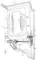
- Steam iron 10 includes a body portion 12, a handle 14 for manipulating the steam iron, a forward or nose portion 16, and an electrically heated soleplate 18.
- a water containing reservoir or tank 20 is formed within body portion 12 of steam iron 10 and contains a supply of water for the generation of steam.
- the reservoir is located above skirt 21 of iron 10.
- steam iron 10 includes a fillport 29 by which reservoir 20 is periodically filled by the user.
- Reservoir 20 may include a transparent or translucent window (not shown) by which the level of water in the reservoir can be gauged by the user.
- Iron 10 is provided with a user - operable temperature control 22 to regulate the electric power provided to soleplate 18 and a steam flow control knob 24 which controls the amount of steam issued from steam apertures 25, shown in Figure 3, in soleplate 18 as is conventional in the art.
- Control 22 is connected to a thermostat 27 that periodically opens and closes an electric circuit to supply power to soleplate 18 and thus establish the ironing temperature of the soleplate.
- Thermostat 27 is mounted on post 52 formed on the upper surface of soleplate 18.
- Thermostat 27 includes bimetallic sensing element 54 which overlies steam chamber cover 30 and is connected to second post 56 extending upwardly from the top surface of soleplate 18.
- the soleplate includes a generally U-shaped heater 19 connected via terminals 17 to the source of electrical energy.
- Soleplate 18 includes an interior surface portion 28 enclosed by steam chamber cover 30 to define a steam chamber 32 in which water from reservoir 20 is flashed to steam.
- Steam chamber 32 is bounded by wall member 34.
- Rear portion 34' of wall member 34 is vertically lower than the front portion to permit steam formed in chamber 32 to flow therefrom over the top surfaces of lower portion 34' of wall member 34 and heater 19 into passageway 36.
- Passageway 36 delivers the steam to the plurality of steam apertures 25 in communication therewith.
- Steam chamber cover 30 includes a relatively large opening 38 overlying steam chamber 32.
- the cover further includes a relatively smaller opening 40 communicating with surge chamber 42 formed in the soleplate.
- Cover 30 includes a third opening 41 through which the top portion of mounting post 56 extends.
- Thermostat 27 is connected by suitable means (not shown) to control 22.
- Knob 24 is connected via rod 44 to a metering valve 46.
- rod 44 moves axially to regulate the operation of the metering valve to control the flow of water from reservoir 20 through opening 38 and then into chamber 32.
- Iron 10 may further include a water spray nozzle 48 mounted at the forward or nose portion 16.
- Spray nozzle 48 enables the user of the iron to emit a spray of water droplets onto the object to be ironed which is positioned in the path of movement of the iron.
- the spray function is used when ironing certain fabrics.
- soleplate 18 includes surge chamber 42. Under the user's control, a jet of water is suddenly introduced into the surge chamber to produce a relatively large quantity of steam.
- the surge function increases the speed and effectiveness of the steam iron in removing wrinkles from certain fabrics by enabling the user of the iron to selectively generate relatively large quantities of steam at intermittent times in the ironing process.
- a control knob 50 is mounted at the top of housing 12 and provides the user with the ability to control a jet of water supplied from reservoir 20 into surge chamber 42 via conduit 43.
- a seal 47 prevents water leakage between water reservoir 20 and skirt 21 of iron 10.
- a suitable control for delivering water into surge chamber 42 is disclosed in United States Patent 5,136,796, issued August 11, 1992 and assigned to the same assignee as the assignee hereof.
- Seal means 60 preferably includes a first relatively large circular portion 62. Seal means 60 further includes a pair of circumferentially spaced relatively smaller circular portions 64 and 66. Portions 64 and 66 are connected to the relatively larger circular portion 62 to form ear-like protuberances. Although ear-like protuberances 64 and 66 are shown as being integral with relatively large portion 62, it should be specifically understood that the ear-like protuberances 64 and 66 may be formed separately from portion 62. As shall be more fully explained, it also should be understood that ear-like protuberance 66 may be eliminated without departing from the scope of the present invention.
- Relatively large portion 62 of seal means 60 seals opening 38 while ear-like protuberance 64 seals opening 40.
- Portion 62 is generally ring-like and includes an opening 68 through which water flows from reservoir 20 through opening 38 underlying opening 68 into chamber 32.
- Ear-like protuberance 64 includes a relatively small diameter opening 70 which overlies opening 40 in cover 30. Water flows from reservoir 20 through openings 70 and 40 into surge chamber 42 when the user activates control 50 to obtain a surge of steam.
- Ear-like protuberance 64 includes a downwardly extending leg-like portion 72 which extends through opening 40. Leg-like portion 72 extends below the lower surface of cover 30 and into surge chamber 32. Leg-like portion 72 includes a discharge flow opening 74 which directs the water supplied to surge chamber 42 in a tangential flow path relative to the lower surface of cover 30.
- Discharge opening 74 directs the stream of water flowing into surge chamber 42 rearwardly towards bimetallic sensing element 54 of thermostat 27.
- Post 56 is physically connected to element 54.
- Element 54 is thus responsive to temperature changes of post 56.
- the temperature of the portion of the soleplate adjacent post 56 will be lowered.
- sensing element 54 will sense a requirement for additional flow of electrical energy to heater 19.
- thermostat 27 will not accurately sense the cooling of the soleplate as the surge of water comes into contact therewith.
- the thermostat will allow the soleplate temperature to cool below desired operating levels.
- Ear-like protuberance 66 of seal means 60 is provided to balance the seal forces acting on seal means 60.
- the seal force acting on protuberance 66 balances the seal forces acting on protuberance 64.
- Protuberance 66 includes a downwardly extending leg portion (not shown) which is similar to leg-portion 72 and extends through a relatively small opening formed in cover 30. Although it is preferable to have second protuberance 66, it is not essential for satisfactory functioning of the invention. Protuberance 66 specifically may be eliminated if protuberance 64 is separate from seal portion 62.
- Discharge opening 74 formed in leg 72 is tapered outwardly so that the stream of water discharged from the opening expands. It is believed that the expansion of the stream of water results in atomization thereof. Atomization of the water flowing into the surge chamber will enable the water to be converted to steam at a faster rate.
- the seal means of the present invention permits a designer of an iron to place the thermostat in a position remote from the water inlet into the surge chamber without degrading the performance of the iron under surge conditions.
Landscapes
- Engineering & Computer Science (AREA)
- Textile Engineering (AREA)
- Irons (AREA)
- Waste-Gas Treatment And Other Accessory Devices For Furnaces (AREA)
Claims (4)
- Fer à repasser (10) électrique comportant:une plaque formant semelle (18) qui présente une surface du haut et une surface du bas;un couvercle (30) de plaque formant semelle raccordé à la surface du haut de la plaque formant semelle, qui comprend une première ouverture (38) et une seconde ouverture (40) pour écoulement de fluides;un boîtier (12) raccordé au couvercle (30) de la plaque formant semelle;ladite plaque formant semelle (18) et ledit couvercle (30) de la plaque formant semelle comprenant des premiers moyens (34') constituant une boîte à vapeur (32) et des seconds moyens (34) constituant une chambre (42) de refoulement;un récipient (20) d'eau situé dans le boîtier (12) et possédant un orifice (29) d'admission d'eau pour une première commande de l'écoulement et au moins une paire d'orifices de sortie d'eau qui comportent ladite première ouverture (38) et ladite seconde ouverture (40) pour écoulement de fluides;des moyens (24, 44, 46) formant valve qui contrôlent le débit d'eau provenant dudit récipient (20) d'eau vers ladite boîte (32) à vapeur à travers ladite première ouverture (38) pour écoulement ménagée dans ledit couvercle (30) de la plaque formant semelle;un moyen (50) de contrôle de l'écoulement destiné à contrôler le débit d'eau provenant du récipient (20) d'eau vers la chambre (42) de refoulement à travers ladite seconde ouverture (40) pour écoulement ménagée dans ledit couvercle (30) de la plaque formant semelle;des moyens (27, 54, 56) détecteurs de température placés en situation relative de transmission de chaleur avec la plaque (18) formant semelle et montés en étroite proximité relative avec ladite chambre (42) de refoulement afin de réguler la température de la plaque formant semellecaractérisé par des moyens (60) formant dispositifs d'étanchéité recouvrant lesdites première et seconde ouvertures pour écoulement, qui comprennent une première partie (62) en contact étanche avec la première ouverture (38) pour écoulement et une seconde partie (64) en contact étanche avec la seconde ouverture (40) pour écoulement, ladite seconde partie comprenant un premier jambage (72) qui s'étend à travers la seconde ouverture (40) pour écoulement sous la surface inférieure du couvercle (30) et qui possède un moyen définissant un ajutage (74) destiné à diriger l'eau provenant dudit récipient (20) d'eau jusque dans ladite chambre (42) de refoulement selon un trajet d'écoulement tangentiel par rapport à la surface inférieure du couvercle ; et
ledit ajutage (74) dirigeant l'eau qui s'écoule à travers ladite seconde ouverture (40) pour écoulement vers lesdits moyens (27, 54, 56) détecteurs de température. - Fer à repasser électrique selon la Revendication 1 dans lequel la première partie (62) desdits moyens (60) formant dispositifs d'étanchéité est aménagée en faisant corps avec la seconde partie (64).
- Fer à repasser électrique selon la Revendication 1 ou la Revendication 2 dans lequel la première partie (62) comporte un organe d'étanchéité circulaire de diamètre relativement grand et la seconde partie (64) comporte un organe d'étanchéité circulaire de diamètre relativement petit qui est accolé à l'organe d'étanchéité circulaire (62) de grand diamètre.
- Fer à repasser électrique selon la Revendication 1, la Revendication 2 ou la Revendication 3 dans lequel les moyens (60) formant dispositifs d'étanchéité comprennent une troisième partie (66) raccordée à la première partie (62) et espacée de la seconde partie (64) et recouvrant une troisième ouverture pour écoulement de fluide ménagée dans ledit couvercle (30) de la plaque formant semelle, ladite troisième partie comprenant un moyen formant jambage qui s'étend à travers cette troisième ouverture.
Applications Claiming Priority (2)
| Application Number | Priority Date | Filing Date | Title |
|---|---|---|---|
| US08/132,416 US5345703A (en) | 1993-10-06 | 1993-10-06 | Steam iron seal with tangential flow for surge |
| US132416 | 1998-08-11 |
Publications (2)
| Publication Number | Publication Date |
|---|---|
| EP0647735A1 EP0647735A1 (fr) | 1995-04-12 |
| EP0647735B1 true EP0647735B1 (fr) | 1997-11-05 |
Family
ID=22453954
Family Applications (1)
| Application Number | Title | Priority Date | Filing Date |
|---|---|---|---|
| EP94307108A Expired - Lifetime EP0647735B1 (fr) | 1993-10-06 | 1994-09-28 | Etanchéité de fer à repasser électrique à vapeur |
Country Status (5)
| Country | Link |
|---|---|
| US (1) | US5345703A (fr) |
| EP (1) | EP0647735B1 (fr) |
| AU (1) | AU671772B2 (fr) |
| CA (1) | CA2132812C (fr) |
| DE (1) | DE69406625T2 (fr) |
Families Citing this family (12)
| Publication number | Priority date | Publication date | Assignee | Title |
|---|---|---|---|---|
| US5628131A (en) * | 1995-12-18 | 1997-05-13 | Black & Decker Inc. | Steam surge system for an electric steam iron |
| US5704143A (en) * | 1996-08-19 | 1998-01-06 | Black & Decker Inc. | Dual surge iron with steam generating areas |
| US5829175A (en) * | 1996-09-20 | 1998-11-03 | Black & Decker Inc. | Steam iron with all temperature steam production |
| EP1537359B1 (fr) * | 2002-08-26 | 2012-09-12 | Koninklijke Philips Electronics N.V. | Appareil electrique a production de vapeur |
| FR2853671B1 (fr) * | 2003-04-14 | 2005-09-16 | Kai Tung Augustine Fung | Fer a repasser a generateur de vapeur |
| FR2858636B1 (fr) * | 2003-08-05 | 2006-03-17 | Rowenta Werke Gmbh | Fer a repasser avec fonction de defroissage vertical |
| DE10357545B4 (de) * | 2003-12-10 | 2007-04-26 | Braun Gmbh | Elektrisches Dampfbügeleisen mit Entkalkungsfunktion |
| US20070220784A1 (en) * | 2006-03-22 | 2007-09-27 | Wen-Ching Li | Intelligent steam iron |
| US20100257761A1 (en) * | 2009-04-08 | 2010-10-14 | Lung Wai Choi | Electric iron with a synchronizing temperature display |
| US20100257760A1 (en) * | 2009-04-08 | 2010-10-14 | Lung Wai Choi | Electric steam iron with a low temperature steam control system |
| ES2420032B1 (es) * | 2012-02-17 | 2014-06-17 | Bsh Electrodom�Sticos Espa�A S.A. | Junta y plancha a vapor |
| US10801159B2 (en) * | 2017-06-14 | 2020-10-13 | Tsann Kuen (Zhangzhou) Enterprise Co., Ltd. | Water tube and a steamer having the same |
Family Cites Families (11)
| Publication number | Priority date | Publication date | Assignee | Title |
|---|---|---|---|---|
| US3407522A (en) * | 1962-06-19 | 1968-10-29 | Sunbeam Corp | Pressing iron |
| US3711972A (en) * | 1971-11-05 | 1973-01-23 | Westinghouse Electric Corp | Steam iron |
| US3849916A (en) * | 1972-11-10 | 1974-11-26 | Gen Electric | Self-cleaning steam iron |
| CA1030055A (fr) * | 1973-12-13 | 1978-04-25 | William E. Davidson | Fer a vapeur |
| US3872613A (en) * | 1974-05-14 | 1975-03-25 | Gen Electric | Self-cleaning surge iron |
| CH598399A5 (fr) * | 1976-07-21 | 1978-04-28 | Henzirohs L Jura Elektroappara | |
| US4091551A (en) * | 1976-10-28 | 1978-05-30 | General Electric Company | Extra capacity steam iron |
| CH619999A5 (fr) * | 1977-05-09 | 1980-10-31 | Henzirohs L Jura Elektroappara | |
| US4433231A (en) * | 1981-05-04 | 1984-02-21 | General Electric Company | Electric iron having stacked thermostat assembly with integral overtemperature protection control |
| JPS6054079A (ja) * | 1983-09-02 | 1985-03-28 | Canon Inc | 電子フアイルシステム |
| JPS61162996A (ja) * | 1985-01-11 | 1986-07-23 | 松下電器産業株式会社 | スチ−ムアイロン |
-
1993
- 1993-10-06 US US08/132,416 patent/US5345703A/en not_active Expired - Fee Related
-
1994
- 1994-09-23 CA CA002132812A patent/CA2132812C/fr not_active Expired - Fee Related
- 1994-09-28 DE DE69406625T patent/DE69406625T2/de not_active Expired - Lifetime
- 1994-09-28 EP EP94307108A patent/EP0647735B1/fr not_active Expired - Lifetime
- 1994-09-29 AU AU74345/94A patent/AU671772B2/en not_active Ceased
Also Published As
| Publication number | Publication date |
|---|---|
| AU7434594A (en) | 1995-04-27 |
| CA2132812C (fr) | 1996-04-16 |
| CA2132812A1 (fr) | 1995-04-07 |
| EP0647735A1 (fr) | 1995-04-12 |
| DE69406625D1 (de) | 1997-12-11 |
| DE69406625T2 (de) | 1998-03-05 |
| AU671772B2 (en) | 1996-09-05 |
| US5345703A (en) | 1994-09-13 |
Similar Documents
| Publication | Publication Date | Title |
|---|---|---|
| EP0647735B1 (fr) | Etanchéité de fer à repasser électrique à vapeur | |
| US3711972A (en) | Steam iron | |
| CA1183445A (fr) | Fer a repasser | |
| EP0543533B1 (fr) | Fer à repasser électrique à vapeur | |
| US5924224A (en) | Steam iron with anti-drip device | |
| US4535556A (en) | Steam ironing apparatus with a separate water reservoir | |
| JP4731492B2 (ja) | スチームアイロン装置 | |
| US3599357A (en) | Electric pressing iron | |
| US4233763A (en) | Steam iron with low temperature soleplate | |
| US2322593A (en) | Pressing iron | |
| US3823498A (en) | Self cleaning steam iron | |
| EP0543534B1 (fr) | Fer à repasser électrique à vapeur | |
| US3986282A (en) | Steam iron | |
| US3041757A (en) | Steam and liquid spray iron | |
| CA1064811A (fr) | Fer a repasser a thermostat | |
| EP1355000B1 (fr) | Fer à repasser à vapeur avec chambre de vaporisation | |
| EP0497470B1 (fr) | Fer à repasser électrique | |
| EP0552923A1 (fr) | Buse de pulvérisation pour fer à repasser électrique | |
| US2729904A (en) | Hand pressing steam and sprinkling iron | |
| US3474552A (en) | Steam iron valve structure | |
| US3496661A (en) | Steam iron water valve structure | |
| US3156054A (en) | Flooded boiler steam or spray iron | |
| US3003266A (en) | Steaming and dampening iron | |
| US3497976A (en) | Steam iron water valve wick structure | |
| US3045370A (en) | Steam iron with position controlled valve |
Legal Events
| Date | Code | Title | Description |
|---|---|---|---|
| PUAI | Public reference made under article 153(3) epc to a published international application that has entered the european phase |
Free format text: ORIGINAL CODE: 0009012 |
|
| AK | Designated contracting states |
Kind code of ref document: A1 Designated state(s): DE FR GB IT |
|
| 17P | Request for examination filed |
Effective date: 19950909 |
|
| GRAG | Despatch of communication of intention to grant |
Free format text: ORIGINAL CODE: EPIDOS AGRA |
|
| 17Q | First examination report despatched |
Effective date: 19970123 |
|
| GRAH | Despatch of communication of intention to grant a patent |
Free format text: ORIGINAL CODE: EPIDOS IGRA |
|
| GRAH | Despatch of communication of intention to grant a patent |
Free format text: ORIGINAL CODE: EPIDOS IGRA |
|
| GRAA | (expected) grant |
Free format text: ORIGINAL CODE: 0009210 |
|
| AK | Designated contracting states |
Kind code of ref document: B1 Designated state(s): DE FR GB IT |
|
| PG25 | Lapsed in a contracting state [announced via postgrant information from national office to epo] |
Ref country code: IT Free format text: LAPSE BECAUSE OF FAILURE TO SUBMIT A TRANSLATION OF THE DESCRIPTION OR TO PAY THE FEE WITHIN THE PRE;WARNING: LAPSES OF ITALIAN PATENTS WITH EFFECTIVE DATE BEFORE 2007 MAY HAVE OCCURRED AT ANY TIME BEFORE 2007. THE CORRECT EFFECTIVE DATE MAY BE DIFFERENT FROM THE ONE RECORDED.SCRIBED TIME-LIMIT Effective date: 19971105 |
|
| REF | Corresponds to: |
Ref document number: 69406625 Country of ref document: DE Date of ref document: 19971211 |
|
| ET | Fr: translation filed | ||
| PLBE | No opposition filed within time limit |
Free format text: ORIGINAL CODE: 0009261 |
|
| STAA | Information on the status of an ep patent application or granted ep patent |
Free format text: STATUS: NO OPPOSITION FILED WITHIN TIME LIMIT |
|
| 26N | No opposition filed | ||
| REG | Reference to a national code |
Ref country code: GB Ref legal event code: IF02 |
|
| PGFP | Annual fee paid to national office [announced via postgrant information from national office to epo] |
Ref country code: GB Payment date: 20090929 Year of fee payment: 16 |
|
| PGFP | Annual fee paid to national office [announced via postgrant information from national office to epo] |
Ref country code: DE Payment date: 20090929 Year of fee payment: 16 |
|
| GBPC | Gb: european patent ceased through non-payment of renewal fee |
Effective date: 20100928 |
|
| REG | Reference to a national code |
Ref country code: FR Ref legal event code: ST Effective date: 20110531 |
|
| REG | Reference to a national code |
Ref country code: DE Ref legal event code: R119 Ref document number: 69406625 Country of ref document: DE Effective date: 20110401 |
|
| PG25 | Lapsed in a contracting state [announced via postgrant information from national office to epo] |
Ref country code: DE Free format text: LAPSE BECAUSE OF NON-PAYMENT OF DUE FEES Effective date: 20110401 Ref country code: FR Free format text: LAPSE BECAUSE OF NON-PAYMENT OF DUE FEES Effective date: 20100930 |
|
| PG25 | Lapsed in a contracting state [announced via postgrant information from national office to epo] |
Ref country code: GB Free format text: LAPSE BECAUSE OF NON-PAYMENT OF DUE FEES Effective date: 20100928 |
|
| PGFP | Annual fee paid to national office [announced via postgrant information from national office to epo] |
Ref country code: FR Payment date: 20091006 Year of fee payment: 16 |