EP0648878A1 - Entoilage thermocollant comportant une nappe de fibres entremêlées dans des fils de trame texturés et son procédé de fabrication - Google Patents
Entoilage thermocollant comportant une nappe de fibres entremêlées dans des fils de trame texturés et son procédé de fabrication Download PDFInfo
- Publication number
- EP0648878A1 EP0648878A1 EP94490045A EP94490045A EP0648878A1 EP 0648878 A1 EP0648878 A1 EP 0648878A1 EP 94490045 A EP94490045 A EP 94490045A EP 94490045 A EP94490045 A EP 94490045A EP 0648878 A1 EP0648878 A1 EP 0648878A1
- Authority
- EP
- European Patent Office
- Prior art keywords
- filaments
- fibers
- threads
- weft threads
- interlining
- Prior art date
- Legal status (The legal status is an assumption and is not a legal conclusion. Google has not performed a legal analysis and makes no representation as to the accuracy of the status listed.)
- Granted
Links
Images
Classifications
-
- D—TEXTILES; PAPER
- D04—BRAIDING; LACE-MAKING; KNITTING; TRIMMINGS; NON-WOVEN FABRICS
- D04H—MAKING TEXTILE FABRICS, e.g. FROM FIBRES OR FILAMENTARY MATERIAL; FABRICS MADE BY SUCH PROCESSES OR APPARATUS, e.g. FELTS, NON-WOVEN FABRICS; COTTON-WOOL; WADDING ; NON-WOVEN FABRICS FROM STAPLE FIBRES, FILAMENTS OR YARNS, BONDED WITH AT LEAST ONE WEB-LIKE MATERIAL DURING THEIR CONSOLIDATION
- D04H3/00—Non-woven fabrics formed wholly or mainly of yarns or like filamentary material of substantial length
- D04H3/08—Non-woven fabrics formed wholly or mainly of yarns or like filamentary material of substantial length characterised by the method of strengthening or consolidating
- D04H3/14—Non-woven fabrics formed wholly or mainly of yarns or like filamentary material of substantial length characterised by the method of strengthening or consolidating with bonds between thermoplastic yarns or filaments produced by welding
-
- D—TEXTILES; PAPER
- D04—BRAIDING; LACE-MAKING; KNITTING; TRIMMINGS; NON-WOVEN FABRICS
- D04H—MAKING TEXTILE FABRICS, e.g. FROM FIBRES OR FILAMENTARY MATERIAL; FABRICS MADE BY SUCH PROCESSES OR APPARATUS, e.g. FELTS, NON-WOVEN FABRICS; COTTON-WOOL; WADDING ; NON-WOVEN FABRICS FROM STAPLE FIBRES, FILAMENTS OR YARNS, BONDED WITH AT LEAST ONE WEB-LIKE MATERIAL DURING THEIR CONSOLIDATION
- D04H1/00—Non-woven fabrics formed wholly or mainly of staple fibres or like relatively short fibres
- D04H1/40—Non-woven fabrics formed wholly or mainly of staple fibres or like relatively short fibres from fleeces or layers composed of fibres without existing or potential cohesive properties
- D04H1/58—Non-woven fabrics formed wholly or mainly of staple fibres or like relatively short fibres from fleeces or layers composed of fibres without existing or potential cohesive properties by applying, incorporating or activating chemical or thermoplastic bonding agents, e.g. adhesives
- D04H1/64—Non-woven fabrics formed wholly or mainly of staple fibres or like relatively short fibres from fleeces or layers composed of fibres without existing or potential cohesive properties by applying, incorporating or activating chemical or thermoplastic bonding agents, e.g. adhesives the bonding agent being applied in wet state, e.g. chemical agents in dispersions or solutions
- D04H1/66—Non-woven fabrics formed wholly or mainly of staple fibres or like relatively short fibres from fleeces or layers composed of fibres without existing or potential cohesive properties by applying, incorporating or activating chemical or thermoplastic bonding agents, e.g. adhesives the bonding agent being applied in wet state, e.g. chemical agents in dispersions or solutions at spaced points or locations
-
- D—TEXTILES; PAPER
- D04—BRAIDING; LACE-MAKING; KNITTING; TRIMMINGS; NON-WOVEN FABRICS
- D04H—MAKING TEXTILE FABRICS, e.g. FROM FIBRES OR FILAMENTARY MATERIAL; FABRICS MADE BY SUCH PROCESSES OR APPARATUS, e.g. FELTS, NON-WOVEN FABRICS; COTTON-WOOL; WADDING ; NON-WOVEN FABRICS FROM STAPLE FIBRES, FILAMENTS OR YARNS, BONDED WITH AT LEAST ONE WEB-LIKE MATERIAL DURING THEIR CONSOLIDATION
- D04H1/00—Non-woven fabrics formed wholly or mainly of staple fibres or like relatively short fibres
- D04H1/40—Non-woven fabrics formed wholly or mainly of staple fibres or like relatively short fibres from fleeces or layers composed of fibres without existing or potential cohesive properties
- D04H1/44—Non-woven fabrics formed wholly or mainly of staple fibres or like relatively short fibres from fleeces or layers composed of fibres without existing or potential cohesive properties the fleeces or layers being consolidated by mechanical means, e.g. by rolling
- D04H1/46—Non-woven fabrics formed wholly or mainly of staple fibres or like relatively short fibres from fleeces or layers composed of fibres without existing or potential cohesive properties the fleeces or layers being consolidated by mechanical means, e.g. by rolling by needling or like operations to cause entanglement of fibres
- D04H1/492—Non-woven fabrics formed wholly or mainly of staple fibres or like relatively short fibres from fleeces or layers composed of fibres without existing or potential cohesive properties the fleeces or layers being consolidated by mechanical means, e.g. by rolling by needling or like operations to cause entanglement of fibres by fluid jet
-
- D—TEXTILES; PAPER
- D04—BRAIDING; LACE-MAKING; KNITTING; TRIMMINGS; NON-WOVEN FABRICS
- D04H—MAKING TEXTILE FABRICS, e.g. FROM FIBRES OR FILAMENTARY MATERIAL; FABRICS MADE BY SUCH PROCESSES OR APPARATUS, e.g. FELTS, NON-WOVEN FABRICS; COTTON-WOOL; WADDING ; NON-WOVEN FABRICS FROM STAPLE FIBRES, FILAMENTS OR YARNS, BONDED WITH AT LEAST ONE WEB-LIKE MATERIAL DURING THEIR CONSOLIDATION
- D04H1/00—Non-woven fabrics formed wholly or mainly of staple fibres or like relatively short fibres
- D04H1/40—Non-woven fabrics formed wholly or mainly of staple fibres or like relatively short fibres from fleeces or layers composed of fibres without existing or potential cohesive properties
- D04H1/44—Non-woven fabrics formed wholly or mainly of staple fibres or like relatively short fibres from fleeces or layers composed of fibres without existing or potential cohesive properties the fleeces or layers being consolidated by mechanical means, e.g. by rolling
- D04H1/46—Non-woven fabrics formed wholly or mainly of staple fibres or like relatively short fibres from fleeces or layers composed of fibres without existing or potential cohesive properties the fleeces or layers being consolidated by mechanical means, e.g. by rolling by needling or like operations to cause entanglement of fibres
- D04H1/498—Non-woven fabrics formed wholly or mainly of staple fibres or like relatively short fibres from fleeces or layers composed of fibres without existing or potential cohesive properties the fleeces or layers being consolidated by mechanical means, e.g. by rolling by needling or like operations to cause entanglement of fibres entanglement of layered webs
-
- D—TEXTILES; PAPER
- D04—BRAIDING; LACE-MAKING; KNITTING; TRIMMINGS; NON-WOVEN FABRICS
- D04H—MAKING TEXTILE FABRICS, e.g. FROM FIBRES OR FILAMENTARY MATERIAL; FABRICS MADE BY SUCH PROCESSES OR APPARATUS, e.g. FELTS, NON-WOVEN FABRICS; COTTON-WOOL; WADDING ; NON-WOVEN FABRICS FROM STAPLE FIBRES, FILAMENTS OR YARNS, BONDED WITH AT LEAST ONE WEB-LIKE MATERIAL DURING THEIR CONSOLIDATION
- D04H13/00—Other non-woven fabrics
-
- D—TEXTILES; PAPER
- D04—BRAIDING; LACE-MAKING; KNITTING; TRIMMINGS; NON-WOVEN FABRICS
- D04H—MAKING TEXTILE FABRICS, e.g. FROM FIBRES OR FILAMENTARY MATERIAL; FABRICS MADE BY SUCH PROCESSES OR APPARATUS, e.g. FELTS, NON-WOVEN FABRICS; COTTON-WOOL; WADDING ; NON-WOVEN FABRICS FROM STAPLE FIBRES, FILAMENTS OR YARNS, BONDED WITH AT LEAST ONE WEB-LIKE MATERIAL DURING THEIR CONSOLIDATION
- D04H3/00—Non-woven fabrics formed wholly or mainly of yarns or like filamentary material of substantial length
- D04H3/02—Non-woven fabrics formed wholly or mainly of yarns or like filamentary material of substantial length characterised by the method of forming fleeces or layers, e.g. reorientation of yarns or filaments
- D04H3/04—Non-woven fabrics formed wholly or mainly of yarns or like filamentary material of substantial length characterised by the method of forming fleeces or layers, e.g. reorientation of yarns or filaments in rectilinear paths, e.g. crossing at right angles
-
- D—TEXTILES; PAPER
- D04—BRAIDING; LACE-MAKING; KNITTING; TRIMMINGS; NON-WOVEN FABRICS
- D04H—MAKING TEXTILE FABRICS, e.g. FROM FIBRES OR FILAMENTARY MATERIAL; FABRICS MADE BY SUCH PROCESSES OR APPARATUS, e.g. FELTS, NON-WOVEN FABRICS; COTTON-WOOL; WADDING ; NON-WOVEN FABRICS FROM STAPLE FIBRES, FILAMENTS OR YARNS, BONDED WITH AT LEAST ONE WEB-LIKE MATERIAL DURING THEIR CONSOLIDATION
- D04H3/00—Non-woven fabrics formed wholly or mainly of yarns or like filamentary material of substantial length
- D04H3/08—Non-woven fabrics formed wholly or mainly of yarns or like filamentary material of substantial length characterised by the method of strengthening or consolidating
- D04H3/10—Non-woven fabrics formed wholly or mainly of yarns or like filamentary material of substantial length characterised by the method of strengthening or consolidating with bonds between yarns or filaments made mechanically
- D04H3/11—Non-woven fabrics formed wholly or mainly of yarns or like filamentary material of substantial length characterised by the method of strengthening or consolidating with bonds between yarns or filaments made mechanically by fluid jet
-
- D—TEXTILES; PAPER
- D04—BRAIDING; LACE-MAKING; KNITTING; TRIMMINGS; NON-WOVEN FABRICS
- D04H—MAKING TEXTILE FABRICS, e.g. FROM FIBRES OR FILAMENTARY MATERIAL; FABRICS MADE BY SUCH PROCESSES OR APPARATUS, e.g. FELTS, NON-WOVEN FABRICS; COTTON-WOOL; WADDING ; NON-WOVEN FABRICS FROM STAPLE FIBRES, FILAMENTS OR YARNS, BONDED WITH AT LEAST ONE WEB-LIKE MATERIAL DURING THEIR CONSOLIDATION
- D04H5/00—Non woven fabrics formed of mixtures of relatively short fibres and yarns or like filamentary material of substantial length
- D04H5/02—Non woven fabrics formed of mixtures of relatively short fibres and yarns or like filamentary material of substantial length strengthened or consolidated by mechanical methods, e.g. needling
- D04H5/03—Non woven fabrics formed of mixtures of relatively short fibres and yarns or like filamentary material of substantial length strengthened or consolidated by mechanical methods, e.g. needling by fluid jet
-
- Y—GENERAL TAGGING OF NEW TECHNOLOGICAL DEVELOPMENTS; GENERAL TAGGING OF CROSS-SECTIONAL TECHNOLOGIES SPANNING OVER SEVERAL SECTIONS OF THE IPC; TECHNICAL SUBJECTS COVERED BY FORMER USPC CROSS-REFERENCE ART COLLECTIONS [XRACs] AND DIGESTS
- Y10—TECHNICAL SUBJECTS COVERED BY FORMER USPC
- Y10T—TECHNICAL SUBJECTS COVERED BY FORMER US CLASSIFICATION
- Y10T428/00—Stock material or miscellaneous articles
- Y10T428/24—Structurally defined web or sheet [e.g., overall dimension, etc.]
- Y10T428/24802—Discontinuous or differential coating, impregnation or bond [e.g., artwork, printing, retouched photograph, etc.]
- Y10T428/24826—Spot bonds connect components
Definitions
- the present invention relates to fusible interlining for clothing pieces, consisting of a interlining support on one face of which have been deposited seals of hot-melt polymer.
- the supports for interlining, in particular fusible, are generally divided into two categories: the textile supports themselves and the nonwovens.
- the textile supports proper are supports which are obtained by weaving or knitting yarns, while the nonwovens are obtained by constitution and consolidation of a sheet of fibers or filaments.
- Nonwovens are less expensive, but they have an irregular distribution, in direction, of the fibers or filaments; therefore not only can this result in density differences and surface irregularities, but also in insufficient dimensional stability: the nonwoven can be irreversibly deformed under the effect of an extension, which causes in the case of a fusible interlining poor stabilization of the piece of clothing on which said nonwoven has been fused.
- the textile supports themselves are preferred in applications where the aforementioned drawbacks of nonwovens are prohibitive, the embodiment by weaving or knitting giving them homogeneity, in particular directional, which is lacking to nonwovens.
- the actual textile supports have less volume and a less pleasant feel.
- the main drawback of this composite intended for interlining lies in its manufacturing cost which combines both that of a knitted fabric or a fabric and that of a nonwoven.
- the aim sought by the applicant is to propose a fusible interlining whose support meets the desired characteristics, combining the properties of the textile support proper and of the nonwoven, without having the disadvantage of the manufacturing cost. It is moreover sought to have a sufficient elasticity of the support to keep with the fusible interfacing its capacity to marry all the given forms of the garment.
- said interlining consists in known manner of at least one nonwoven web of fibers or entangled filaments, having a given general direction and one side of which is coated with hot melt polymer dots.
- it comprises so-called weft yarns which are continuous and textured filament yarns and which are arranged transversely to the above-mentioned general direction, being linked to said sheet by virtue of the entanglement of the fibers or filaments of the sheet.
- the interlining support of the invention does not include a knitted fabric or a fabric but only weft threads which are arranged parallel to each other and which are secured to the nonwoven web thanks to the entanglement of the fibers or filaments constituting this web.
- the weft threads give the support of the invention a transverse dimensional stability which is comparable to that of a woven textile support or of a woven mesh knit.
- the cohesion of the support is comparable to that of a nonwoven, but it should be noted that in the field of interlining it is mainly stability and resistance in the transverse direction which is sought; this therefore does not constitute a particular drawback.
- the weft threads are threads of textured continuous filaments.
- the presence of the crimp due to the texturing gives the nonwoven web, the transverse extension capacity which is sought for a fusible interlining, having to adapt to the shapes given to the piece of clothing that it strengthens.
- This capacity for extension must result in an elasticity in the weft direction of at least a few percent, in particular of the order of 5%, to much larger values, in particular of the order of 20%.
- the presence of crimp due to texturing improves the attachment of the fibers or filaments of the nonwoven web and the weft threads. This is further improved in the case of textured yarns with a large volume, obtained by the air jet texturing technique from at least two multifilament yarns, a first yarn called core yarn and a second yarn. says effect thread.
- the effect yarn creates loops around the core yarn, in which the fibers or filaments of the nonwoven ply hang.
- the fusible interlining of the invention consists of a single nonwoven web of fibers or entangled filaments, the weft threads being partially visible on one face of said web; moreover, the hot-melt polymer dots are arranged on said face.
- the polymer When applying the hot-melt polymer dots, the polymer locally ensures the cohesion of the elements with which it is in contact; in the present case, it can therefore be both fibers or filaments of the nonwoven web, among which the fibers or filaments producing the entanglement of the weft threads, and textured continuous threads making the weft.
- An improved cohesion is therefore obtained between the weft yarns and the nonwoven web, this cohesion being ensured not only by the entanglement of the fibers or filaments of the web and the weft yarns but also by bonding of these thanks to the hot melt polymer dots.
- the first embodiment of the invention it is possible to significantly reduce the action of the fluid jets, due to the additional cohesion provided by points of hot-melt polymer on the face of the sheet where the wires of weft are partially visible, so as to obtain a fusible interfacing having good bulk and hand characteristics.
- This contribution of cohesion due to the polymer is particularly sensitive when the density of the weft threads is equal to or greater than 3 threads / cm.
- the fusible interlining of the invention comprises two nonwoven plies arranged on either side of the weft threads.
- the weft threads are sandwiched between the two layers and are linked to the two layers by virtue of the entanglement of the fibers or filaments of the two layers.
- This second version is used in particular to have a coating surface for the hot-melt polymer points which is as flat and as regular as possible, when it is a fine coating, that is to say say a coating which has a number of polymer points per square centimeter of the order of or greater than 60.
- the second nonwoven web, on which the dots of hot-melt polymer are disposed has a grammage lower than that of the first web.
- the interlining making from 50 to 65 g / m2
- the second nonwoven web had a grammage of 10 to 20 g / m2 and the first web from 25 to 35 g / m2.
- the yarns used for the production of the weft yarns are retractable textured yarns, and the entanglement of the yarns or filaments of the nonwoven web or possibly nonwoven webs is obtained by the action of jets of fluid.
- high pressure in this case, the interlining support has after the action of the fluid jets underwent a thermal shrinkage treatment. This has the advantage of further increasing the volume of the fusible interfacing.
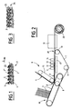
- the fusible interlining 1 of the invention comprises a nonwoven web of fibers 2 which are entangled between them and which are also entangled in threads 3, called weft threads, which are arranged transversely to the general direction D of the tablecloth 4.
- the weft threads 3 are textured continuous filament threads and are not joined together except by the entanglement of the fibers 2 constituting the nonwoven web 4.
- the number of weft threads 3 is at least 3 threads per centimeter and the deposition of the dots 22 of hot-melt polymer is carried out on the face 5 of the sheet 4 according to which the weft threads 3 are the most visible. There is thus a reinforcement of the cohesion of the weft threads and of the nonwoven web because in addition to the entanglement of the fibers 2 around the weft threads 3 there is a surface bonding of certain fibers 2 ′ and of some weft threads by the polymer of points 22.
- the production of the support 18 for interlining is obtained on a binding installation by fluid jets such as that which is shown in FIG. 2.
- This installation 6 comprises an endless belt 7, which is a metal grid stretched between three drums 8, 9 and 1O, the drum 1O being driven in rotation by means not shown.
- injector ramps 2 supplied under high pressure.
- FIG. 2 shows four ramps 11, 12, 13, 14, supplied for example under pressures respectively equal to 40 bars for the first injector 11, 60 bars for the second injector 12, 70 bars for the third injector 13 and 8O bars for the fourth injector 14.
- the belt 7 is preceded by two feeding assemblies.
- the first assembly 15 is a second mat on which the nonwoven web 4 formed of the fibers 2 has been formed by any suitable known means.
- the fibers 2 are present on the second mat 15 in the form of a sheet which has no cohesion, but which is held by suction.
- the second mat 15 is arranged obliquely, above the first mat 7, at the level of the inlet drum 8.
- the second supply assembly 16 consists of a mobile system for covering the wires with pliers or hooks, capable of receiving, blocking the two ends of the sections of wires 3 which are supplied by means not shown, to keep them taut. , parallel to each other and to convey them to the first mat 7 in the zone 21 thereof in which the second mat 15 deposits the sheet 4 of fibers or filaments. It is possible to adjust the density of yarns 3 for a given length of ply 4 as a function of the relative speeds of the second set 16 and the first mat 7.
- the ply 4 is placed above the wires 3.
- the assembly consisting of the superposition of the wires 3 and of the sheet 4 of fibers or filaments 2 passes successively under the four injectors 11,12,13,14.
- the water which is sprayed from said injectors not only strikes directly the fibers or filaments 2 but also rebounds on the metallic grid constituting the carpet 7 and thereby displaces the fibers or filaments 2 of the sheet 4 relative to each other.
- the texture and the diameter of the metal wires which constitute the grid are chosen to ensure the best interlacing efficiency when the web 4 passes under the injector ramps 11 to 14.
- the diameter of the metal wires was 0.5 mm and the grid had an opening of 30, that is to say that the recess between the meshes of the grid represented 30% of the total surface of the latter. this.
- the water coming from the injectors 11 to 14 is recovered in a suction box 17 which is placed under the upper strand of the mat 7 in line with the injector rails 11 to 14. It is recycled by a set of pumps not shown.
- the fibers or filaments 2 are entangled in each other to the point of ensuring the cohesion of said ply 4 but also they or they are entangled around the yarns 3, called weft yarns.
- This assembly 18 thus consolidated enters a drying and possibly thermofixation tunnel 19, regulated for example between 110 ° C. or 180 ° C., then is wound up in the form of a coil 2O.
- the interlining support 18 is then covered with a point by point coating based on a heat-bonding resin.
- This coating is deposited on the face 5 of the support 18 on which the weft threads 3 are most visible. In the example shown in FIG. 2, this is the face which faces the first mat 7.
- the deposition of resin points is obtained by means of engraved cylinders, the resin being able to be deposited either in the state of paste 5 (cylinder type screen printing) or in the powder state (cylinder engraved in hollow type rotogravure). It can also be obtained by means of a perforated cylinder of the printing type in which the dough is fed inside the cylinder, then pushed by a doctor blade through the perforations from the inside towards the outside of the cylinder. The support 18 on which the resin dots are deposited then passes through a drying tunnel.
- the fibers 2 were polyester fibers of 1.5 dtex; the sheet 4 had a grammage of 25 g / m2, the weft threads 3 were textured false twist threads fixed with polyester of 1OO dtex, placed on the sheet 4 at the rate of six threads per centimeter.
- the fusible resin was in the form of a polyamide paste; it was deposited using a perforated impression type cylinder with about 40 holes per cm2. Each perforation had a diameter of about 0.6 mm.
- the fusible interlining thus produced has the qualities of voluminosity and feel of the nonwoven, and also the dynamometric characteristics and dimensional stability of a support of the fabric or weft knitting type.
- an increase in the dynamometric resistance of the support 18 has been noted after application of the resin points, due to the bonding with the weft threads 3 of the fibers 2 'which, entangled with weft threads 3, are arranged on the surface of the support 18.
- FIG. 2 shows an installation 6 in which the action of the water jets is only carried out on one side of the support 18.
- an installation is implemented with at least two sets of ramps injectors acting respectively on the two faces of the support so as to obtain a better entanglement of the fibers 2 around the weft threads 3.
- FIG. 2 also shows an installation 6 in which a single ply 4 is supplied.
- This same installation can easily include a third supply assembly for a second ply 23 which would be deposited on the first mat 7 in line with the input drum 8 before the zone 21.
- the weft threads 3 would be disposed between the two layers 4 and 23, before the assembly passes under the injectors.
- the weft son 3 In the interlining support obtained, the weft son 3 would be sandwiched between the two layers 4, 23 whose fibers or filaments 2 would be entangled with each other and around said weft son 3.
- thermobonding resin is a fine coating, that is to say having a number of points per cm2 of l 'order of or greater than 60, which requires that the surface to be coated is perfectly flat and even.
- interlining for light article making of the order of 50 to 65 g / m2, there was a coating from 12 to 14 g / m2, weft threads of the order of 5 - 6 g / m2, a first layer making from 25 to 35 g / m2 and a second layer making from 10 to 20 g / m2.
- the weft yarns 3 being textured yarns, an excellent hooking and entangling effect is obtained thanks to the natural crimping thereof.
- These textured yarns can be of the fixed false twist type, but preferably they will be textured yarns with a large volume, obtained by the texturing technique by air jets from at least two multifilament yarns, namely a first yarn. said core wire and a second wire said effect wire, the overfeeding of the effect wire being significantly greater than that of the core wire.
- This high-volume textured yarn has a loop-shaped texturing, which further promotes entanglement with the fibers or filaments 2 during the action of the jets of fluid.
- the weft threads 3 can also be retractable textured threads. In this case we obtain the retraction of the weft son in the drying oven 19 or during a subsequent operation. The retraction of the wires 3 makes it possible to further increase the volume of the support 18 and to obtain a greater elasticity of the said support 18 in the transverse direction.
- the sheet can be made up of all kinds of continuous fibers or filaments, including of the spun or melt-blown type.
Landscapes
- Engineering & Computer Science (AREA)
- Textile Engineering (AREA)
- Mechanical Engineering (AREA)
- Chemical & Material Sciences (AREA)
- Chemical Kinetics & Catalysis (AREA)
- Dispersion Chemistry (AREA)
- General Chemical & Material Sciences (AREA)
- Details Of Garments (AREA)
- Woven Fabrics (AREA)
- Nonwoven Fabrics (AREA)
- Laminated Bodies (AREA)
- Yarns And Mechanical Finishing Of Yarns Or Ropes (AREA)
- Treatments For Attaching Organic Compounds To Fibrous Goods (AREA)
- Manufacturing Of Multi-Layer Textile Fabrics (AREA)
- Adhesives Or Adhesive Processes (AREA)
- Reinforced Plastic Materials (AREA)
- Auxiliary Devices For And Details Of Packaging Control (AREA)
- Treatment Of Fiber Materials (AREA)
Abstract
Description
- La présente invention concerne l'entoilage thermocollant pour pièces d'habillement, constitué d'un support d'entoilage sur une face duquel ont été déposés des joints de polymère thermofusible.
- On répartit généralement les supports pour entoilage , notamment thermocollant, en deux catégories: les supports textiles proprement dits et les non-tissés. Les supports textiles proprement dits sont des supports qui sont obtenus par tissage ou tricotage de fils, tandis que les non-tissés sont obtenus par constitution et consolidation d'une nappe de fibres ou de filaments.
- Chacun de ces types de supports présente des avantages et des inconvénients et il revient à l'utilisateur de faire son choix en fonction des propriétés requises pour son entoilage.
- Les non-tissés sont moins coûteux, mais ils présentent une répartition irrégulière, en direction , des fibres ou filaments ; de ce fait non seulement cela peut se traduire par des écarts de densité et des irrégularités de surface, mais encore par une stabilité dimensionnelle insuffisante : le non-tissé peut être déformé de manière irréversible sous l'effet d'une extension , ce qui occasionne dans le cas d'un entoilage thermocollant une mauvaise stabilisation de la pièce d'habillement sur laquelle ledit non-tissé a été thermocollé. Ainsi , malgré leur prix plus élevé, les supports textiles proprement dits sont préférés dans les applications où les inconvénients précités des non-tissés sont rédhibitoires, le mode de réalisation par tissage ou tricotage leur conférant l'homogénéité , en particulier directionnelle, qui fait défaut aux non-tissés.
- Cependant comparativement aux non-tissés, les supports textiles proprement dits ont moins de volume et un toucher moins agréable.
- On a déjà cherché à obtenir un support pour entoilage qui ait à la fois le volume et le toucher d'un non-tissé et les propriétés de cohésion , de nervosité et de non-extension du support tissé ou tricoté.
- Ceci est obtenu, dans le document FR.2.645.18O, en juxtaposant un support textile tricoté ou tissé et au moins une nappe non-tissée et en liant ces deux éléments par aiguilletage par jets fluide.
- L'inconvénient principal de ce composite destiné à l'entoilage réside dans son coût de fabrication qui cumule à la fois celui d'un tricot ou d'un tissu et celui d'un non-tissé.
- Le but visé par le demandeur est de proposer un entoilage thermocollant dont le support répond aux caractéristiques recherchées , alliant les propriétés du support textile proprement dit et du non-tissé, sans présenter l'inconvénient du coût de fabrication. Il est de plus recherché d'avoir une élasticité suffisante du support pour garder à l'entoilage thermocollant sa capacité à épouser toutes les formes données du vêtement.
- Ce but est parfaitement atteint par l'entoilage thermocollant de l'invention, ledit entoilage est constitué de manière connue d'au moins une nappe non-tissée de fibres ou de filaments enchevêtrés, ayant une direction générale donnée et dont une face est revêtue de points de polymère thermofusible. De manière caractéristique il comporte des fils dits de trame qui sont des fils de filaments continus et texturés et, qui sont disposés transversalement à la direction générale précitée, étant liés à ladite nappe grâce à l'enchevêtrement des fibres ou des filaments de la nappe.
- Contrairement au composite décrit et revendiqué dans le document FR.2.645.18O, le support pour entoilage de l'invention ne comporte pas un tricot ou un tissu mais uniquement des fils de trame qui sont disposés parallèlement les uns aux autres et qui sont solidarisés à la nappe non-tissée grâce à l'enchevêtrement des fibres ou des filaments constitutifs de cette nappe.
- Les fils de trame confèrent au support de l'invention une stabilité dimensionnelle transversale qui est comparable à celle d'un support textile tissé ou d'un tricot mailles tramées. Dans le sens longitudinal , la cohésion du support est comparable à celle d'un non-tissé, mais il est à noter que dans le domaine de l'entoilage c'est principalement la stabilité et la résistance dans le sens transversal qui est recherché; ceci ne constitue donc pas un inconvénient particulier.
- De plus les fils de trame sont des fils de filaments continus texturés. D'une part la présence de la frisure due à la texturation confère à la nappe non-tissée, la capacité d'extension transversale qui est recherchée pour un entoilage thermocollant, devant s'adapter aux formes données à la pièce d'habillement qu'il renforce. Cette capacité d'extension doit se traduire par une élasticité dans le sens trame d'au moins quelques pour-cent notamment de l'ordre de 5 %, jusqu'à des valeurs beaucoup plus importantes, notamment de l'ordre de 20 %.
- D'autre part, la présence de la frisure due à la texturation améliore l'accrochage des fibres ou des filaments de la nappe non-tissée et des fils de trame. Ceci est encore amélioré lorsqu'il s'agit de fils texturés à grande voluminosité , obtenus par la technique de texturation par jet d'air à partir d'au moins deux fils multifilamentaires, un premier fil dit fil d'âme et un second fil dit fil d'effet.
- En effet dans ce type de fil texturé, le fil d'effet réalise autour du fil d'âme des boucles, dans lesquelles viennent s'accrocher les fibres ou les filaments de la nappe non-tissée.
- Dans une première version, l'entoilage thermocollant de l'invention est constitué d'une seule nappe non-tissée de fibres ou de filaments enchevêtrés, les fils de trame étant partiellement apparents sur une face de ladite nappe ; de plus les points de polymère thermofusible sont disposés sur ladite face.
- Lors de l'application des points de polymère thermofusible, le polymère assure localement la cohésion des éléments avec lequel il est en contact ; dans le cas présent, il peut donc s'agir à la fois des fibres ou filaments de la nappe non-tissée, parmi lesquels les fibres ou filaments réalisant l'enchevêtrement des fils de trame, et des fils continus texturés réalisant la trame. On obtient donc une cohésion améliorée entre les fils de trame et la nappe non-tissée, cette cohésion étant assurée non seulement par l'enchevêtrement des fibres ou filaments de la nappe et des fils de trame mais aussi par collage de ceux-ci grâce aux points de polymère thermofusible.
- Grâce à l'apport de cohésion du fait du collage par le polymère, il est possible de diminuer corrélativement l'action d'enchevêtrement lorsque celle-ci est susceptible de produire un effet néfaste. Notamment lorsque l'enchevêtrement des fibres ou filaments de la nappe non-tissée et des fils de trame est obtenu par l'action de jets de fluide haute pression, il a été remarqué que cette action tend à compacter la nappe, c'est-à-dire à lui faire perdre du volume. Ceci peut être un handicap, pour certaines applications d'entoilage thermocollant. De même l'action des jets de fluide haute pression a tendance à modifier la main du support, à lui donner un caractère plus sec. Ainsi, dans la première version de réalisation de l'invention, il est possible de réduire sensiblement l'action des jets de fluide, du fait de la cohésion complémentaire apportée par des points de polymère thermofusible sur la face de la nappe où les fils de trame sont partiellement apparents , de manière à obtenir un entoilage thermocollant ayant de bonnes caractéristiques de voluminosité et de main. Cet apport de cohésion du fait du polymère est particulièrement sensible lorsque la densité des fils de trame est égale ou supérieure à 3 fils/cm.
- Dans une seconde version, l'entoilage thermocollant de l'invention comporte deux nappes non-tissées disposées de part et d'autre des fils de trame. Les fils de trame sont pris en sandwich entre les deux nappes et sont liés aux deux nappes grâce à l'enchevêtrement des fibres ou filaments des deux nappes.
- On fait appel à cette seconde version notamment pour avoir une surface d'enduction pour les points de polymère thermofusible qui soit la plus plane et la plus régulière possible, lorsqu'il s'agit d'une enduction fine, c'est-à-dire une enduction qui comporte un nombre de points de polymère au centimètre carré de l'ordre de ou supérieure à 60.
- De préférence, dans ce cas, la seconde nappe non-tissée, sur laquelle sont disposés les points de polymère thermofusible a un grammage inférieur à celui de la première nappe. Par exemple un entoilage thermocollant pour article d'habillement léger, l'entoilage faisant de 50 à 65 g/m², la seconde nappe non-tissée avait un grammage de 10 à 20 g/m² et la première nappe de 25 à 35 g/m².
- Avantageusement les fils mis en oeuvre pour la réalisation des fils de trame sont des fils texturés rétractables , et l'enchevêtrement des fils ou filaments de la nappe non-tissée ou éventuellement des nappes non-tissées est obtenu par l'action de jets de fluide haute pression ; dans ce cas, le support pour entoilage a subi après l'action des jets de fluide un traitement de rétraction thermique. Ceci présente l'avantage d'augmenter encore la voluminosité de l'entoilage thermocollant.
- L'invention sera mieux comprise à la lecture de la description qui va être faite d'un exemple de réalisation d'un entoilage thermocollant comportant une nappe non-tissée de fibres ou filaments enchevêtrés avec des fils de trame en fils de filaments continus texturés illustré par le dessin annexé dans lequel :
- La figure 1 est une représentation schématique en coupe d'un entoilage thermocollant à une seule nappe non-tissée,
- La figure 2 est une représentation schématique de côté de l'installation de liage de la nappe non-tissée et des fils de trame par l'action de jets de fluide.
- La figure 3 est une représentation schématique en coupe d'un entoilage thermocollant à deux nappes non-tissées.
- L'entoilage thermocollant 1, de l'invention comporte une nappe non-tissée de fibres 2 qui sont enchevêtrées entre-elles et qui sont également enchevêtrées dans des fils 3, dits fils de trame, qui sont disposés transversalement à la direction générale D de la nappe 4.
- Conformément à l'invention, les fils de trame 3 sont des fils de filaments continus texturés et ne sont solidarisés entre-eux que grâce à l'enchevêtrement des fibres 2 constitutives de la nappe non-tissée 4.
- Le nombre de fils de trame 3 est au moins de 3 fils par centimètre et le dépôt des points 22 de polymère thermofusible est réalisé sur la face 5 de la nappe 4 selon laquelle les fils de trame 3 sont les plus apparents. On a ainsi un renforcement de la cohésion des fils de trame et de la nappe non-tissée du fait qu'en plus de l'enchevêtrement des fibres 2 autour des fils de trame 3 on a un collage superficiel de certaines fibres 2' et de certains fils de trame par le polymère des points 22.
- La réalisation du support 18 pour entoilage est obtenu sur une installation de liage par jets de fluide telle que celle qui est représentée à la figure 2.
- Cette installation 6 comporte un tapis sans fin 7, qui est une grille métallique tendue entre trois tambours 8,9 et 1O, le tambour 1O étant entraîné en rotation par des moyens non-représentés. Au-dessus du brin supérieur du tapis 7 sont disposées des rampes d'injecteur 2 alimentées sous haute pression. On a représenté sur la figure 2 quatre rampes 11,12,13,14, alimentées par exemple sous des pressions respectivement égales à 4O bars pour le premier injecteur 11, 6O bars pour le deuxième injecteur 12, 7O bars pour le troisième injecteur 13 et 8O bars pour le quatrième injecteur 14.
- Le tapis 7 est précédé de deux ensembles d'alimentation. Le premier ensemble 15 est un second tapis sur lequel a été formée la nappe 4 non-tissée constituée des fibres 2 par tout moyen connu approprié. Les fibres 2 se présentent sur le second tapis 15 sous forme d'une nappe qui n'a pas de cohésion, mais qui est maintenue par aspiration.
- Comme cela ressort clairement de la figure 2, le second tapis 15 est disposé obliquement , au-dessus du premier tapis 7, au niveau du tambour d'entrée 8.
- Le second ensemble d'alimentation 16 est constitué d'un système mobile de nappage des fils à pinces ou crochets, apte à recevoir , à bloquer les deux extrémités des tronçons de fils 3 qui sont alimentés par des moyens non représentés , à les maintenir tendus , parallèles les uns aux autres et à les acheminer jusqu'au premier tapis 7 dans la zone 21 de celui-ci dans laquelle le second tapis 15 dépose la nappe 4 de fibres ou de filaments. Il est possible de régler la densité de fils 3 pour une longueur de nappe 4 donnée en fonction des vitesses relatives du second ensemble 16 et du premier tapis 7.
- Dans l'exemple illustré, la nappe 4 se trouve placée au-dessus des fils 3.
- L'ensemble constitué de la superposition des fils 3 et de la nappe 4 de fibres ou filaments 2 passe successivement sous les quatre injecteurs 11,12,13,14. L'eau qui est projetée depuis lesdits injecteurs non seulement frappe directement les fibres ou filaments 2 mais également rebondit sur la grille métallique constitutive du tapis 7 et de ce fait déplace les fibres ou filaments 2 de la nappe 4 les uns par rapport aux autres. La contexture et le diamètre des fils métalliques qui constituent la grille sont choisis pour assurer le meilleur rendement d'entrelacement lors du passage de la nappe 4 sous les rampes à injecteurs 11 à 14. Dans le présent exemple le diamètre des fils métalliques était de O,5mm et la grille avait une ouverture de 3O, c'est-à-dire que l'évidement entre les mailles de la grille représentait 3O% de la surface totale de celle-ci.
- L'eau provenant des injecteurs 11 à 14 est récupérée dans un caisson d'aspiration 17 qui est placé sous le brin supérieur du tapis 7 au droit des rampes d'injecteurs 11 à 14. Elle est recyclée par un jeu de pompes non représenté.
- Dans le support d'entoilage 18 constitué par la nappe 4 et par les fils 3, les fibres ou filaments 2 sont enchevêtrés les uns dans les autres au point d'assurer la cohésion de ladite nappe 4 mais également elles ou ils sont enchevêtrées autour des fils 3, dénommés fils de trame.
- Cet ensemble 18 ainsi consolidé entre dans un tunnel 19 de séchage et éventuellement de thermofixation, régulé par exemple entre 11O°C ou 18O°C ,puis est enroulé sous forme d'une bobine 2O.
- Le support d'entoilage 18 est ensuite recouvert d'une enduction point par point à base d'une résine thermocollante. Cette enduction est déposée sur la face 5 du support 18 sur laquelle les fils de trame 3 sont les plus apparents. Il s'agit, dans l'exemple représenté à la figure 2, de la face qui est tournée vers le premier tapis 7.
- Le dépôt de points de résine est obtenu au moyen de cylindres gravés , la résine pouvant être déposée soit à l'état de pâte 5 (cylindre type sérigraphie) soit à l'état de poudre (cylindre gravé en creux type héliogravure). Il peut aussi être obtenu au moyen d'un cylindre perforé du type impression dans lequel la pâte est alimentée à l'intérieur du cylindre , puis poussée par une racle au travers des perforations de l'intérieur vers l'extérieur du cylindre. Le support 18 sur lequel sont déposés les points de résine passe ensuite dans un tunnel de séchage.
- Dans un exemple précis de réalisation, les fibres 2 étaient des fibres de polyester de 1,5 dtex; la nappe 4 avait un grammage de 25 g/m², les fils de trame 3 étaient des fils texturés fausse torsion fixés de polyester de 1OO dtex, disposés sur la nappe 4 à raison de six fils par centimètre. La résine thermocollante était sous forme de pâte polyamide; elle a été déposée à l'aide d'un cylindre perforé du type impression avec environ 40 trous au cm². Chaque perforation avait un diamètre de l'ordre de O,6 mm.
- L'entoilage thermocollant ainsi réalisé présente les qualités de voluminosité et de toucher du non-tissé, et également les caractéristiques dynamométriques et de stabilité dimensionnelle d'un support du type tissu ou tricot trame. On a remarqué en particulier un accroissement de la résistance dynamométrique du support 18 après application des points de résine, dû au collage avec les fils de trame 3 des fibres 2' qui , enchevêtrées avec des fils de trame 3 , se trouvent disposés en surface du support 18.
- On a représenté sur la figure 2 une installation 6 dans laquelle l'action des jets d'eau n'est réalisée que sur une seule face du support 18. De préférence on met en oeuvre une installation avec au moins deux ensembles de rampes d'injecteurs agissant respectivement sur les deux faces du support de manière à obtenir un meilleur enchevêtrement des fibres 2 autour des fils de trame 3.
- On a également représenté sur la figure 2 une installation 6 dans laquelle une seule nappe 4 est alimentée. Cette même installation peut facilement comporter un troisième ensemble d'alimentation pour une seconde nappe 23 qui serait déposée sur le premier tapis 7 au droit du tambour d'entrée 8 avant la zone 21. Dans ce cas, les fils de trame 3 seraient disposés entre les deux nappes 4 et 23, avant que l'ensemble passe sous les injecteurs. Dans le support d'entoilage obtenu, les fils de trame 3 seraient pris en sandwich entre les deux nappes 4 , 23 dont les fibres ou filaments 2 seraient enchevêtrés les uns aux autres et autour desdits fils de trame 3.
- Cette variante d'entoilage 24 à deux nappes non-tissées 4, 23 est notamment intéressante à mettre en oeuvre lorsque l'enduction de résine thermocollante est une enduction fine, c'est-à-dire ayant un nombre de points au cm² de l'ordre de ou supérieur à 60, qui nécessite que la surface à enduire soit parfaitement plane et régulière. Dans ce cas, de préférence, on dispose une seconde nappe non-tissée 23 plus légère que la première 5. Dans un exemple précis d'entoilage pour article léger, faisant de l'ordre de 50 à 65 g/m², on avait une enduction de 12 à 14 g/m², des fils de trame faisant de l'ordre de 5 - 6 g/m², une première nappe faisant de 25 à 35 g/m² et une seconde nappe de 10 à 20 g/m².
- Les fils de trame 3 étant des fils texturés, on obtient un excellent effet d'accrochage et d'enchevêtrement grâce à la frisure naturelle de ceux-ci. Ces fils texturés peuvent être du type fausse torsion fixée mais de préférence il s'agira de fils texturés à grande voluminosité, obtenus par la technique de texturation par jets d'air à partir d'au moins deux fils multifilamentaires , à savoir un premier fil dit fil d'âme et un second fil dit fil d'effet, la suralimentation du fil d'effet étant nettement supérieure à celle du fil d'âme. Ce fil texturé à haute voluminosité présente une texturation en forme de boucle, qui favorise encore l'enchevêtrement avec les fibres ou filaments 2 lors de l'action des jets de fluide.
- Les fils de trame 3 peuvent également être des fils texturés rétractables. Dans ce cas on obtient la rétraction des fils de trame dans le four de séchage 19 ou lors d'une opération subséquente. La rétraction des fils 3 permet d'accroître encore la voluminosité du support 18 et d'obtenir une élasticité plus importante dudit support 18 dans le sens transversal.
- La nappe peut être constituée de toutes sortes de fibres ou filaments continus, y compris du type spun ou melt-blown.
Claims (7)
- Entoilage thermocollant, comportant au moins une nappe (4) non-tissée de fibres (2) ou de filaments enchevêtrés, ayant une direction générale donnée et dont une face est revêtue de points de polymère thermofusible , caractérisé en ce qu'il comporte des fils dits de trame (3) qui sont des fils de filaments continus texturés, disposés transversalement à la direction générale précitée et liés à ladite nappe grâce à l'enchevêtrement des fibres ou des filaments de la nappe.
- Entoilage selon la revendication 1 caractérisé en ce que les fils de trame sont des fils texturés à grande voluminosité , obtenus par la technique de texturation par jet d'air à partir d'au moins deux fils multifilamentaires , un premier fil dit fil d'âme et un second fil dit fil d'effet, la suralimentation du fil d'effet étant nettement supérieure à celle du fil d'âme.
- Entoilage selon l'une des revendications 1 ou 2 caractérisé en ce qu'il ne comporte qu'une seule nappe non-tissée, les fils de trame étant partiellement apparents sur une face donnée de ladite nappe et en ce que les points de polymère thermofusible sont disposés sur ladite face.
- Entoilage selon la revendication 3 caractérisé en ce que la densité des fils de trame (3) est d'au moins 3 fils par centimètre.
- Entoilage selon l'une des revendications 1 ou 2 caractérisé en ce qu'il comporte deux nappes (5, 23) non-tissées de fibres ou de filaments enchevêtrés (2) entre lesquelles sont pris en sandwich les fils de trame (3), et en ce que le nombre de points de polymère est de l'ordre de ou supérieur à 60 par centimètre carré.
- Procédé de fabrication d'un entoilage thermocollant selon lequel on dépose des points de polymère thermofusible sur une face d'une nappe (4) non-tissée de fibres (2) ou de filaments enchevêtrés, ayant une direction générale donnée, caractérisé en ce que préalablement au dépôt de points de polymère il consiste à :- disposer des fils de trame (3) en filaments continus texturés sur un tapis transporteur constitué d'une grille métallique,- recouvrir les fils de trame d'une nappe (4) non-tissée de fibres ou de filaments non enchevêtrés,- soumettre l'ensemble constitué de la superposition des fils de trame (3) et de la nappe (4) à l'action de jets d'eau haute pression provenant d'injecteurs placés au-dessus de la grille, de manière à réaliser l'enchevêtrement des fibres ou filaments (2) de la nappe (4) entre-eux et avec les fils de trame (3),- soumettre cet ensemble, constituant le support d'entoilage à un traitement ultérieur de séchage et en ce que l'enduction des points de polymère thermofusible est réalisé sur la face du support d'entoilage qui était en contact avec la grille métallique.
- Procédé selon la revendication 6 caractérisé en ce que, les fils de trame étant des fils ou filaments continus texturés rétractables, le traitement ultérieur est un traitement thermique apte à réaliser la rétraction des fils de trame.
Priority Applications (1)
| Application Number | Priority Date | Filing Date | Title |
|---|---|---|---|
| SI9430170T SI0648878T1 (en) | 1993-10-11 | 1994-09-30 | Thermobonded interlining material comprising a fiber layer mixed with texturised weft yarns and process for making the same |
Applications Claiming Priority (2)
| Application Number | Priority Date | Filing Date | Title |
|---|---|---|---|
| FR9312384 | 1993-10-11 | ||
| FR9312384A FR2711151B1 (fr) | 1993-10-11 | 1993-10-11 | Support pour entoilage comportant une nappe de fibres entremêlées dans des fils de trame et son procédé de fabrication. |
Publications (2)
| Publication Number | Publication Date |
|---|---|
| EP0648878A1 true EP0648878A1 (fr) | 1995-04-19 |
| EP0648878B1 EP0648878B1 (fr) | 1998-05-06 |
Family
ID=9451937
Family Applications (1)
| Application Number | Title | Priority Date | Filing Date |
|---|---|---|---|
| EP94490045A Expired - Lifetime EP0648878B1 (fr) | 1993-10-11 | 1994-09-30 | Entoilage thermocollant comportant une nappe de fibres entremêlées dans des fils de trame texturés et son procédé de fabrication |
Country Status (20)
| Country | Link |
|---|---|
| US (2) | US5534330A (fr) |
| EP (1) | EP0648878B1 (fr) |
| JP (1) | JPH07189099A (fr) |
| KR (1) | KR950011683A (fr) |
| CN (1) | CN1121968A (fr) |
| AT (1) | ATE165878T1 (fr) |
| AU (1) | AU676939B2 (fr) |
| CA (1) | CA2133500A1 (fr) |
| CZ (1) | CZ285916B6 (fr) |
| DE (1) | DE69410054T2 (fr) |
| DK (1) | DK0648878T3 (fr) |
| ES (1) | ES2119123T3 (fr) |
| FI (1) | FI944772L (fr) |
| FR (1) | FR2711151B1 (fr) |
| HU (1) | HU215764B (fr) |
| NO (1) | NO300335B1 (fr) |
| PL (1) | PL176467B1 (fr) |
| RU (1) | RU2106442C1 (fr) |
| SI (1) | SI0648878T1 (fr) |
| TR (1) | TR28159A (fr) |
Cited By (1)
| Publication number | Priority date | Publication date | Assignee | Title |
|---|---|---|---|---|
| FR2754278A1 (fr) * | 1996-10-07 | 1998-04-10 | Inventa Ag | Non tisse d'insertion renforce par du fil multifilament et son procede de fabrication |
Families Citing this family (34)
| Publication number | Priority date | Publication date | Assignee | Title |
|---|---|---|---|---|
| FR2745595B1 (fr) * | 1996-02-29 | 1998-05-22 | Picardie Lainiere | Entoilage thermocollant et son procede de fabrication |
| DE19609586C1 (de) * | 1996-03-12 | 1997-06-26 | Freudenberg Carl Fa | Tuftträger |
| FR2749135B1 (fr) * | 1996-05-29 | 1998-08-21 | Picardie Lainiere | Procede de traitement d'un support textile pour entoilage thermocollant a base de fils textures |
| US5950987A (en) * | 1997-06-06 | 1999-09-14 | Tetra Laval Holdings & Finance, Sa | In-line lever actuated valve |
| JP2000034660A (ja) * | 1998-07-17 | 2000-02-02 | Uni Charm Corp | 湿式不織布の製造方法および製造装置 |
| US6387471B1 (en) | 1999-03-31 | 2002-05-14 | Kimberly-Clark Worldwide, Inc. | Creep resistant composite elastic material with improved aesthetics, dimensional stability and inherent latency and method of producing same |
| US6547915B2 (en) | 1999-04-15 | 2003-04-15 | Kimberly-Clark Worldwide, Inc. | Creep resistant composite elastic material with improved aesthetics, dimensional stability and inherent latency and method of producing same |
| US8182457B2 (en) | 2000-05-15 | 2012-05-22 | Kimberly-Clark Worldwide, Inc. | Garment having an apparent elastic band |
| US6833179B2 (en) | 2000-05-15 | 2004-12-21 | Kimberly-Clark Worldwide, Inc. | Targeted elastic laminate having zones of different basis weights |
| US6969441B2 (en) | 2000-05-15 | 2005-11-29 | Kimberly-Clark Worldwide, Inc. | Method and apparatus for producing laminated articles |
| US6939334B2 (en) | 2001-12-19 | 2005-09-06 | Kimberly-Clark Worldwide, Inc. | Three dimensional profiling of an elastic hot melt pressure sensitive adhesive to provide areas of differential tension |
| US6902796B2 (en) | 2001-12-28 | 2005-06-07 | Kimberly-Clark Worldwide, Inc. | Elastic strand bonded laminate |
| US6978486B2 (en) | 2002-07-02 | 2005-12-27 | Kimberly-Clark Worldwide, Inc. | Garment including an elastomeric composite laminate |
| US7316842B2 (en) | 2002-07-02 | 2008-01-08 | Kimberly-Clark Worldwide, Inc. | High-viscosity elastomeric adhesive composition |
| US7316840B2 (en) | 2002-07-02 | 2008-01-08 | Kimberly-Clark Worldwide, Inc. | Strand-reinforced composite material |
| US7015155B2 (en) | 2002-07-02 | 2006-03-21 | Kimberly-Clark Worldwide, Inc. | Elastomeric adhesive |
| US20040006323A1 (en) * | 2002-07-02 | 2004-01-08 | Hall Gregory K. | Garments using elastic strands to enhance performance of elastic barrier adhessive |
| US7335273B2 (en) | 2002-12-26 | 2008-02-26 | Kimberly-Clark Worldwide, Inc. | Method of making strand-reinforced elastomeric composites |
| US6916750B2 (en) | 2003-03-24 | 2005-07-12 | Kimberly-Clark Worldwide, Inc. | High performance elastic laminates made from high molecular weight styrenic tetrablock copolymer |
| US7601657B2 (en) | 2003-12-31 | 2009-10-13 | Kimberly-Clark Worldwide, Inc. | Single sided stretch bonded laminates, and methods of making same |
| DE602005015443D1 (de) * | 2004-05-13 | 2009-08-27 | Humanscale Corp | Gitterstuhlbestandteil |
| US7651653B2 (en) | 2004-12-22 | 2010-01-26 | Kimberly-Clark Worldwide, Inc. | Machine and cross-machine direction elastic materials and methods of making same |
| USD623449S1 (en) | 2005-05-13 | 2010-09-14 | Humanscale Corporation | Mesh backrest for a chair |
| US7478463B2 (en) * | 2005-09-26 | 2009-01-20 | Kimberly-Clark Worldwide, Inc. | Manufacturing process for combining a layer of pulp fibers with another substrate |
| DE102007028263A1 (de) * | 2007-06-15 | 2008-12-18 | Carl Freudenberg Kg | Verbund zur Verwendung in Kleidungsstücken |
| TWM373127U (en) * | 2009-08-06 | 2010-02-01 | Liang-Yang Lin | disassembleable warm-keeping clothing set formed of solar nano-carbon balls composite material |
| DE102010009275A1 (de) * | 2010-02-25 | 2011-08-25 | Trützschler Nonwovens GmbH, 63329 | Vorrichtung zum Verfestigen einer Materialbahn |
| US11832681B2 (en) | 2017-02-03 | 2023-12-05 | Nike, Inc. | Fiber-bound engineered materials formed using engineered scrims |
| US12075884B2 (en) | 2017-02-03 | 2024-09-03 | Nike, Inc. | Fiber-bound engineered materials formed using foundation scrims |
| US12532943B2 (en) | 2017-02-03 | 2026-01-27 | Nike, Inc. | Fiber-bound engineered materials formed as a synthetic leather |
| WO2018144122A1 (fr) * | 2017-02-03 | 2018-08-09 | Nike Innovate C.V. | Matériaux façonnés liés par des fibres formés à l'aide de canevas continus |
| EP3576935A1 (fr) | 2017-02-03 | 2019-12-11 | Nike Innovate C.V. | Matériaux modifiés liés à des fibres formés à l'aide de canevas zonaux |
| WO2018144125A1 (fr) * | 2017-02-03 | 2018-08-09 | Nike Innovate C.V. | Matériaux modifiés liés par des fibres formés à l'aide de canevas d'éléments |
| EP4257002B1 (fr) | 2017-08-16 | 2026-01-28 | Nike Innovate C.V. | Textile non tissé pour chaussure à bord replié enchevêtré |
Citations (8)
| Publication number | Priority date | Publication date | Assignee | Title |
|---|---|---|---|---|
| US4000551A (en) * | 1975-01-15 | 1977-01-04 | Crimpfil Limited | Production of bulky yarns |
| GB1600768A (en) * | 1977-12-09 | 1981-10-21 | Koninkl Aabe Fabriken Bv | Underlays |
| US4319447A (en) * | 1979-03-08 | 1982-03-16 | E. I. Du Pont De Nemours And Company | Method of forming a bulky yarn |
| FR2526818A1 (fr) * | 1982-05-12 | 1983-11-18 | Chomarat Et Cie Ets Fils | Grille textile non tissee |
| EP0200385A2 (fr) * | 1985-04-13 | 1986-11-05 | Heinsco Limited | Procédé de stabilisation d'étoffes tissées, tricotées ou non-tissées et étoffes stabilisées par cette méthode |
| EP0363254A1 (fr) * | 1988-10-04 | 1990-04-11 | Lainiere De Picardie | Entoilage thermocollant à base de microfilaments |
| EP0466563A1 (fr) * | 1990-07-12 | 1992-01-15 | LAINIERE DE PICARDIE: Société anonyme | Entoilage thermocollant à base de microfibres et procédé pour l'obtenir |
| EP0501842A1 (fr) * | 1991-02-25 | 1992-09-02 | Lainiere De Picardie | Textile d'entoilage composite |
Family Cites Families (18)
| Publication number | Priority date | Publication date | Assignee | Title |
|---|---|---|---|---|
| US3510389A (en) * | 1965-08-03 | 1970-05-05 | Kendall & Co | Spot-bonded nonwoven fabric |
| CH571669A4 (fr) * | 1968-04-23 | 1975-04-30 | ||
| JPS6037208B2 (ja) * | 1976-02-25 | 1985-08-24 | 三菱レイヨン株式会社 | 不織布及びその製造方法 |
| DE3032349A1 (de) * | 1980-08-28 | 1982-03-04 | Fa. Carl Freudenberg, 6940 Weinheim | Einlagevliesstoff |
| DE3038664C2 (de) * | 1980-10-13 | 1984-04-05 | Fa. Carl Freudenberg, 6940 Weinheim | Aufbügelbarer Einlagevliesstoff |
| JPS58136878A (ja) * | 1982-02-03 | 1983-08-15 | 日本バイリーン株式会社 | 接着芯地の製造方法 |
| US4450196A (en) * | 1983-02-17 | 1984-05-22 | Crown Textile Company | Composite fusible interlining fabric and method |
| US4514455A (en) * | 1984-07-26 | 1985-04-30 | E. I. Du Pont De Nemours And Company | Nonwoven fabric for apparel insulating interliner |
| DE3610029A1 (de) * | 1986-03-25 | 1987-10-01 | Freudenberg Carl Fa | Aufbuegelbarer einlageverbundstoff |
| FR2606603B1 (fr) * | 1986-11-14 | 1991-03-22 | Picardie Lainiere | Produit thermocollant et procede de fabrication |
| US4737396A (en) * | 1987-02-04 | 1988-04-12 | Crown Textile Company | Composite fusible interlining fabric |
| GB8715464D0 (en) * | 1987-07-01 | 1987-08-05 | Courtaulds Plc | Warp/weft sheet |
| FR2645180B1 (fr) * | 1989-03-31 | 1991-10-25 | Picardie Lainiere | |
| US5034261A (en) * | 1989-12-14 | 1991-07-23 | Institut Textile De France | Thermo-bonding interlining containing microfilaments |
| US5171309A (en) * | 1990-05-11 | 1992-12-15 | E. I. Du Pont De Nemours And Company | Polyesters and their use in compostable products such as disposable diapers |
| FR2686628A1 (fr) * | 1992-01-28 | 1993-07-30 | Perfojet Sa | Structure textile complexe a base de nappes fibreuses non tissees et procede et installation pour son obtention. |
| US5437918A (en) * | 1992-11-11 | 1995-08-01 | Mitsui Toatsu Chemicals, Inc. | Degradable non-woven fabric and preparation process thereof |
| US5288536A (en) * | 1993-05-28 | 1994-02-22 | E. I. Du Pont De Nemours And Company | Hydraulic-jet-treated stitchbonded fabric |
-
1993
- 1993-10-11 FR FR9312384A patent/FR2711151B1/fr not_active Expired - Fee Related
-
1994
- 1994-09-30 DK DK94490045T patent/DK0648878T3/da active
- 1994-09-30 AT AT94490045T patent/ATE165878T1/de active
- 1994-09-30 ES ES94490045T patent/ES2119123T3/es not_active Expired - Lifetime
- 1994-09-30 EP EP94490045A patent/EP0648878B1/fr not_active Expired - Lifetime
- 1994-09-30 SI SI9430170T patent/SI0648878T1/xx unknown
- 1994-09-30 DE DE69410054T patent/DE69410054T2/de not_active Expired - Fee Related
- 1994-09-30 CA CA002133500A patent/CA2133500A1/fr not_active Abandoned
- 1994-10-04 US US08/317,577 patent/US5534330A/en not_active Expired - Fee Related
- 1994-10-07 JP JP6270291A patent/JPH07189099A/ja active Pending
- 1994-10-10 PL PL94305387A patent/PL176467B1/pl unknown
- 1994-10-10 CN CN94117041A patent/CN1121968A/zh active Pending
- 1994-10-10 NO NO943822A patent/NO300335B1/no unknown
- 1994-10-10 HU HU9402927A patent/HU215764B/hu not_active IP Right Cessation
- 1994-10-10 AU AU75726/94A patent/AU676939B2/en not_active Ceased
- 1994-10-10 KR KR1019940025814A patent/KR950011683A/ko not_active Withdrawn
- 1994-10-10 RU RU94036755A patent/RU2106442C1/ru active
- 1994-10-11 TR TR01046/94A patent/TR28159A/xx unknown
- 1994-10-11 CZ CZ942513A patent/CZ285916B6/cs not_active IP Right Cessation
- 1994-10-11 FI FI944772A patent/FI944772L/fi unknown
-
1995
- 1995-06-01 US US08/457,874 patent/US5593533A/en not_active Expired - Fee Related
Patent Citations (8)
| Publication number | Priority date | Publication date | Assignee | Title |
|---|---|---|---|---|
| US4000551A (en) * | 1975-01-15 | 1977-01-04 | Crimpfil Limited | Production of bulky yarns |
| GB1600768A (en) * | 1977-12-09 | 1981-10-21 | Koninkl Aabe Fabriken Bv | Underlays |
| US4319447A (en) * | 1979-03-08 | 1982-03-16 | E. I. Du Pont De Nemours And Company | Method of forming a bulky yarn |
| FR2526818A1 (fr) * | 1982-05-12 | 1983-11-18 | Chomarat Et Cie Ets Fils | Grille textile non tissee |
| EP0200385A2 (fr) * | 1985-04-13 | 1986-11-05 | Heinsco Limited | Procédé de stabilisation d'étoffes tissées, tricotées ou non-tissées et étoffes stabilisées par cette méthode |
| EP0363254A1 (fr) * | 1988-10-04 | 1990-04-11 | Lainiere De Picardie | Entoilage thermocollant à base de microfilaments |
| EP0466563A1 (fr) * | 1990-07-12 | 1992-01-15 | LAINIERE DE PICARDIE: Société anonyme | Entoilage thermocollant à base de microfibres et procédé pour l'obtenir |
| EP0501842A1 (fr) * | 1991-02-25 | 1992-09-02 | Lainiere De Picardie | Textile d'entoilage composite |
Cited By (2)
| Publication number | Priority date | Publication date | Assignee | Title |
|---|---|---|---|---|
| FR2754278A1 (fr) * | 1996-10-07 | 1998-04-10 | Inventa Ag | Non tisse d'insertion renforce par du fil multifilament et son procede de fabrication |
| DE19641236A1 (de) * | 1996-10-07 | 1998-04-16 | Inventa Ag | Multifilamentgarnverstärktes Einlagevlies und Verfahren zu dessen Herstellung |
Also Published As
| Publication number | Publication date |
|---|---|
| FI944772A0 (fi) | 1994-10-11 |
| CN1121968A (zh) | 1996-05-08 |
| JPH07189099A (ja) | 1995-07-25 |
| FR2711151B1 (fr) | 1996-01-05 |
| ES2119123T3 (es) | 1998-10-01 |
| HU215764B (hu) | 1999-02-01 |
| FI944772A7 (fi) | 1995-04-12 |
| PL305387A1 (en) | 1995-04-18 |
| RU2106442C1 (ru) | 1998-03-10 |
| CZ251394A3 (en) | 1995-04-12 |
| TR28159A (tr) | 1996-02-13 |
| FI944772L (fi) | 1995-04-12 |
| PL176467B1 (pl) | 1999-05-31 |
| NO943822L (no) | 1995-04-12 |
| AU7572694A (en) | 1995-04-27 |
| US5534330A (en) | 1996-07-09 |
| CA2133500A1 (fr) | 1995-04-12 |
| KR950011683A (ko) | 1995-05-15 |
| FR2711151A1 (fr) | 1995-04-21 |
| DE69410054T2 (de) | 1998-11-26 |
| EP0648878B1 (fr) | 1998-05-06 |
| CZ285916B6 (cs) | 1999-11-17 |
| HU9402927D0 (en) | 1995-01-30 |
| AU676939B2 (en) | 1997-03-27 |
| NO943822D0 (no) | 1994-10-10 |
| SI0648878T1 (en) | 1998-10-31 |
| RU94036755A (ru) | 1996-10-10 |
| ATE165878T1 (de) | 1998-05-15 |
| US5593533A (en) | 1997-01-14 |
| HUT75446A (en) | 1997-05-28 |
| DK0648878T3 (da) | 1999-01-18 |
| DE69410054D1 (de) | 1998-06-10 |
| NO300335B1 (no) | 1997-05-12 |
Similar Documents
| Publication | Publication Date | Title |
|---|---|---|
| EP0648878B1 (fr) | Entoilage thermocollant comportant une nappe de fibres entremêlées dans des fils de trame texturés et son procédé de fabrication | |
| EP0390622B1 (fr) | Textile destiné à l'entoilage et son procédé de fabrication | |
| EP0118373B1 (fr) | Structure textile ajourée et procédé pour son obtention | |
| EP1117860B1 (fr) | Procede pour la realisation d'un materiau non-tissu complexe et materiau ainsi obtenu | |
| EP1226297B1 (fr) | Procede pour la realisation de nappes non tissees dont la cohesion est obtenue par l'action de jets de fluide | |
| EP0481867B1 (fr) | Support textile, tissé ou tricoté trame, pour entoilage thermocollant | |
| FR2705698A1 (fr) | Procédé de fabrication d'une nappe de non-tissé constituée de filaments continus liés entre eux et nappe ainsi obtenue. | |
| CA2011687C (fr) | Textile thermocollant destine a l'entoilage et son procede de fabrication | |
| FR2649130A1 (fr) | Procede et dispositif de fabrication de produits textiles a partir de fibres et/ou filaments et produits obtenus | |
| EP0804885B1 (fr) | Col a support textile de renforcement | |
| EP0501842A1 (fr) | Textile d'entoilage composite | |
| WO1993000465A1 (fr) | Procede pour realiser un non-tisse, non-tisse obtenu notamment par ce procede et installation pour la fabrication de ce non-tisse | |
| FR2692602A1 (fr) | Etoffe non tissée ainsi que le procédé et le dispositif pour la fabrication de celle-ci. | |
| EP0810314B1 (fr) | Procédé de traitement d'un support textile pour entoilage thermocollant à base de fils texturés | |
| EP0783608B1 (fr) | Procede et dispositif de fabrication de produits textiles a partir de fibres et/ou de filaments, et produits obtenus | |
| EP0466563B1 (fr) | Entoilage thermocollant à base de microfibres et procédé pour l'obtenir | |
| EP1136003B1 (fr) | Support textile thermocollant et son procédé de fabrication | |
| EP2443949A1 (fr) | Entoilage thermocollant destiné au renforcement d'une partie d'un article textile | |
| FR2590518A1 (fr) | Nouveau produit composite a base d'armature de fils ou fibres notamment tisses ou tricotes enroulee sur elle-meme | |
| FR2766071A1 (fr) | Procede de fabrication d'un materiau composite pour la protection anti-vandalisme, notamment pour sieges, et materiau composite obtenu | |
| EP1497488B1 (fr) | Non tisse a nappes partiellement liees et ses procede et machine de production. |
Legal Events
| Date | Code | Title | Description |
|---|---|---|---|
| PUAI | Public reference made under article 153(3) epc to a published international application that has entered the european phase |
Free format text: ORIGINAL CODE: 0009012 |
|
| AK | Designated contracting states |
Kind code of ref document: A1 Designated state(s): AT BE CH DE DK ES FR GB GR IE IT LI LU MC NL PT SE |
|
| RAX | Requested extension states of the european patent have changed |
Free format text: LT PAYMENT 941007;SI PAYMENT 941007 |
|
| 17P | Request for examination filed |
Effective date: 19950526 |
|
| GRAG | Despatch of communication of intention to grant |
Free format text: ORIGINAL CODE: EPIDOS AGRA |
|
| GRAG | Despatch of communication of intention to grant |
Free format text: ORIGINAL CODE: EPIDOS AGRA |
|
| GRAH | Despatch of communication of intention to grant a patent |
Free format text: ORIGINAL CODE: EPIDOS IGRA |
|
| 17Q | First examination report despatched |
Effective date: 19970908 |
|
| GRAH | Despatch of communication of intention to grant a patent |
Free format text: ORIGINAL CODE: EPIDOS IGRA |
|
| GRAA | (expected) grant |
Free format text: ORIGINAL CODE: 0009210 |
|
| AK | Designated contracting states |
Kind code of ref document: B1 Designated state(s): AT BE CH DE DK ES FR GB GR IE IT LI LU MC NL PT SE |
|
| AX | Request for extension of the european patent |
Free format text: LT PAYMENT 941007;SI PAYMENT 941007 |
|
| REF | Corresponds to: |
Ref document number: 165878 Country of ref document: AT Date of ref document: 19980515 Kind code of ref document: T |
|
| REG | Reference to a national code |
Ref country code: CH Ref legal event code: EP |
|
| REF | Corresponds to: |
Ref document number: 69410054 Country of ref document: DE Date of ref document: 19980610 |
|
| ITF | It: translation for a ep patent filed | ||
| GBT | Gb: translation of ep patent filed (gb section 77(6)(a)/1977) |
Effective date: 19980618 |
|
| REG | Reference to a national code |
Ref country code: CH Ref legal event code: NV Representative=s name: BOVARD AG PATENTANWAELTE |
|
| REG | Reference to a national code |
Ref country code: IE Ref legal event code: FG4D Free format text: 80183 |
|
| PGFP | Annual fee paid to national office [announced via postgrant information from national office to epo] |
Ref country code: MC Payment date: 19980814 Year of fee payment: 5 |
|
| PGFP | Annual fee paid to national office [announced via postgrant information from national office to epo] |
Ref country code: DK Payment date: 19980819 Year of fee payment: 5 |
|
| PGFP | Annual fee paid to national office [announced via postgrant information from national office to epo] |
Ref country code: AT Payment date: 19980820 Year of fee payment: 5 |
|
| PGFP | Annual fee paid to national office [announced via postgrant information from national office to epo] |
Ref country code: IE Payment date: 19980824 Year of fee payment: 5 |
|
| PGFP | Annual fee paid to national office [announced via postgrant information from national office to epo] |
Ref country code: NL Payment date: 19980825 Year of fee payment: 5 |
|
| PGFP | Annual fee paid to national office [announced via postgrant information from national office to epo] |
Ref country code: PT Payment date: 19980827 Year of fee payment: 5 |
|
| PGFP | Annual fee paid to national office [announced via postgrant information from national office to epo] |
Ref country code: GR Payment date: 19980831 Year of fee payment: 5 |
|
| PGFP | Annual fee paid to national office [announced via postgrant information from national office to epo] |
Ref country code: ES Payment date: 19980916 Year of fee payment: 5 |
|
| PGFP | Annual fee paid to national office [announced via postgrant information from national office to epo] |
Ref country code: DE Payment date: 19980917 Year of fee payment: 5 |
|
| PGFP | Annual fee paid to national office [announced via postgrant information from national office to epo] |
Ref country code: SE Payment date: 19980922 Year of fee payment: 5 Ref country code: GB Payment date: 19980922 Year of fee payment: 5 Ref country code: CH Payment date: 19980922 Year of fee payment: 5 |
|
| PGFP | Annual fee paid to national office [announced via postgrant information from national office to epo] |
Ref country code: LU Payment date: 19980925 Year of fee payment: 5 |
|
| PGFP | Annual fee paid to national office [announced via postgrant information from national office to epo] |
Ref country code: FR Payment date: 19980930 Year of fee payment: 5 |
|
| REG | Reference to a national code |
Ref country code: ES Ref legal event code: FG2A Ref document number: 2119123 Country of ref document: ES Kind code of ref document: T3 |
|
| PGFP | Annual fee paid to national office [announced via postgrant information from national office to epo] |
Ref country code: BE Payment date: 19981016 Year of fee payment: 5 |
|
| REG | Reference to a national code |
Ref country code: PT Ref legal event code: SC4A Free format text: AVAILABILITY OF NATIONAL TRANSLATION Effective date: 19980708 |
|
| REG | Reference to a national code |
Ref country code: DK Ref legal event code: T3 |
|
| PLBE | No opposition filed within time limit |
Free format text: ORIGINAL CODE: 0009261 |
|
| STAA | Information on the status of an ep patent application or granted ep patent |
Free format text: STATUS: NO OPPOSITION FILED WITHIN TIME LIMIT |
|
| 26N | No opposition filed | ||
| PG25 | Lapsed in a contracting state [announced via postgrant information from national office to epo] |
Ref country code: SE Free format text: THE PATENT HAS BEEN ANNULLED BY A DECISION OF A NATIONAL AUTHORITY Effective date: 19990929 |
|
| LTIE | Lt: invalidation of european patent or patent extension | ||
| PG25 | Lapsed in a contracting state [announced via postgrant information from national office to epo] |
Ref country code: LU Free format text: LAPSE BECAUSE OF NON-PAYMENT OF DUE FEES Effective date: 19990930 Ref country code: LI Free format text: LAPSE BECAUSE OF NON-PAYMENT OF DUE FEES Effective date: 19990930 Ref country code: IE Free format text: LAPSE BECAUSE OF NON-PAYMENT OF DUE FEES Effective date: 19990930 Ref country code: GR Free format text: LAPSE BECAUSE OF NON-PAYMENT OF DUE FEES Effective date: 19990930 Ref country code: GB Free format text: LAPSE BECAUSE OF NON-PAYMENT OF DUE FEES Effective date: 19990930 Ref country code: DK Free format text: LAPSE BECAUSE OF NON-PAYMENT OF DUE FEES Effective date: 19990930 Ref country code: CH Free format text: LAPSE BECAUSE OF NON-PAYMENT OF DUE FEES Effective date: 19990930 Ref country code: BE Free format text: LAPSE BECAUSE OF NON-PAYMENT OF DUE FEES Effective date: 19990930 Ref country code: AT Free format text: LAPSE BECAUSE OF NON-PAYMENT OF DUE FEES Effective date: 19990930 |
|
| PG25 | Lapsed in a contracting state [announced via postgrant information from national office to epo] |
Ref country code: ES Free format text: LAPSE BECAUSE OF NON-PAYMENT OF DUE FEES Effective date: 19991001 |
|
| BERE | Be: lapsed |
Owner name: LAINIERE DE PICARDIE Effective date: 19990930 |
|
| PG25 | Lapsed in a contracting state [announced via postgrant information from national office to epo] |
Ref country code: PT Free format text: LAPSE BECAUSE OF NON-PAYMENT OF DUE FEES Effective date: 20000331 Ref country code: MC Free format text: LAPSE BECAUSE OF NON-PAYMENT OF DUE FEES Effective date: 20000331 |
|
| PG25 | Lapsed in a contracting state [announced via postgrant information from national office to epo] |
Ref country code: NL Free format text: LAPSE BECAUSE OF NON-PAYMENT OF DUE FEES Effective date: 20000401 |
|
| REG | Reference to a national code |
Ref country code: CH Ref legal event code: PL |
|
| GBPC | Gb: european patent ceased through non-payment of renewal fee |
Effective date: 19990930 |
|
| PG25 | Lapsed in a contracting state [announced via postgrant information from national office to epo] |
Ref country code: FR Free format text: LAPSE BECAUSE OF NON-PAYMENT OF DUE FEES Effective date: 20000531 |
|
| NLV4 | Nl: lapsed or anulled due to non-payment of the annual fee |
Effective date: 20000401 |
|
| EUG | Se: european patent has lapsed |
Ref document number: 94490045.5 |
|
| PG25 | Lapsed in a contracting state [announced via postgrant information from national office to epo] |
Ref country code: DE Free format text: LAPSE BECAUSE OF NON-PAYMENT OF DUE FEES Effective date: 20000701 |
|
| REG | Reference to a national code |
Ref country code: PT Ref legal event code: MM4A Free format text: LAPSE DUE TO NON-PAYMENT OF FEES Effective date: 20000331 |
|
| REG | Reference to a national code |
Ref country code: FR Ref legal event code: ST |
|
| REG | Reference to a national code |
Ref country code: IE Ref legal event code: MM4A |
|
| REG | Reference to a national code |
Ref country code: DK Ref legal event code: EBP |
|
| REG | Reference to a national code |
Ref country code: ES Ref legal event code: FD2A Effective date: 20001013 |
|
| PG25 | Lapsed in a contracting state [announced via postgrant information from national office to epo] |
Ref country code: IT Free format text: LAPSE BECAUSE OF NON-PAYMENT OF DUE FEES Effective date: 20050930 |