EP0650766A2 - Durch Ansaugen gespeiste Düse für Niederdruckspritzpistolen - Google Patents
Durch Ansaugen gespeiste Düse für Niederdruckspritzpistolen Download PDFInfo
- Publication number
- EP0650766A2 EP0650766A2 EP94307747A EP94307747A EP0650766A2 EP 0650766 A2 EP0650766 A2 EP 0650766A2 EP 94307747 A EP94307747 A EP 94307747A EP 94307747 A EP94307747 A EP 94307747A EP 0650766 A2 EP0650766 A2 EP 0650766A2
- Authority
- EP
- European Patent Office
- Prior art keywords
- air
- orifice
- fluid
- nozzle assembly
- orifices
- Prior art date
- Legal status (The legal status is an assumption and is not a legal conclusion. Google has not performed a legal analysis and makes no representation as to the accuracy of the status listed.)
- Granted
Links
- 239000007921 spray Substances 0.000 title claims abstract description 32
- 239000012530 fluid Substances 0.000 claims abstract description 97
- 238000007493 shaping process Methods 0.000 claims abstract description 45
- 238000000889 atomisation Methods 0.000 claims abstract description 42
- 238000007599 discharging Methods 0.000 claims description 4
- 230000001939 inductive effect Effects 0.000 claims description 2
- 239000003973 paint Substances 0.000 abstract description 48
- 239000002245 particle Substances 0.000 abstract description 9
- 230000001965 increasing effect Effects 0.000 description 16
- 230000005484 gravity Effects 0.000 description 5
- 230000002411 adverse Effects 0.000 description 3
- 239000007788 liquid Substances 0.000 description 3
- 238000000429 assembly Methods 0.000 description 2
- 230000000712 assembly Effects 0.000 description 2
- 238000005507 spraying Methods 0.000 description 2
- 238000003915 air pollution Methods 0.000 description 1
- 238000000151 deposition Methods 0.000 description 1
- 238000004519 manufacturing process Methods 0.000 description 1
- 239000000463 material Substances 0.000 description 1
- 238000011144 upstream manufacturing Methods 0.000 description 1
Images

Classifications
-
- B—PERFORMING OPERATIONS; TRANSPORTING
- B05—SPRAYING OR ATOMISING IN GENERAL; APPLYING FLUENT MATERIALS TO SURFACES, IN GENERAL
- B05B—SPRAYING APPARATUS; ATOMISING APPARATUS; NOZZLES
- B05B7/00—Spraying apparatus for discharge of liquids or other fluent materials from two or more sources, e.g. of liquid and air, of powder and gas
- B05B7/0081—Apparatus supplied with low pressure gas, e.g. "hvlp"-guns; air supplied by a fan
-
- B—PERFORMING OPERATIONS; TRANSPORTING
- B05—SPRAYING OR ATOMISING IN GENERAL; APPLYING FLUENT MATERIALS TO SURFACES, IN GENERAL
- B05B—SPRAYING APPARATUS; ATOMISING APPARATUS; NOZZLES
- B05B7/00—Spraying apparatus for discharge of liquids or other fluent materials from two or more sources, e.g. of liquid and air, of powder and gas
- B05B7/02—Spray pistols; Apparatus for discharge
- B05B7/06—Spray pistols; Apparatus for discharge with at least one outlet orifice surrounding another approximately in the same plane
- B05B7/062—Spray pistols; Apparatus for discharge with at least one outlet orifice surrounding another approximately in the same plane with only one liquid outlet and at least one gas outlet
- B05B7/063—Spray pistols; Apparatus for discharge with at least one outlet orifice surrounding another approximately in the same plane with only one liquid outlet and at least one gas outlet one fluid being sucked by the other
-
- B—PERFORMING OPERATIONS; TRANSPORTING
- B05—SPRAYING OR ATOMISING IN GENERAL; APPLYING FLUENT MATERIALS TO SURFACES, IN GENERAL
- B05B—SPRAYING APPARATUS; ATOMISING APPARATUS; NOZZLES
- B05B7/00—Spraying apparatus for discharge of liquids or other fluent materials from two or more sources, e.g. of liquid and air, of powder and gas
- B05B7/02—Spray pistols; Apparatus for discharge
- B05B7/06—Spray pistols; Apparatus for discharge with at least one outlet orifice surrounding another approximately in the same plane
- B05B7/062—Spray pistols; Apparatus for discharge with at least one outlet orifice surrounding another approximately in the same plane with only one liquid outlet and at least one gas outlet
- B05B7/066—Spray pistols; Apparatus for discharge with at least one outlet orifice surrounding another approximately in the same plane with only one liquid outlet and at least one gas outlet with an inner liquid outlet surrounded by at least one annular gas outlet
-
- B—PERFORMING OPERATIONS; TRANSPORTING
- B05—SPRAYING OR ATOMISING IN GENERAL; APPLYING FLUENT MATERIALS TO SURFACES, IN GENERAL
- B05B—SPRAYING APPARATUS; ATOMISING APPARATUS; NOZZLES
- B05B7/00—Spraying apparatus for discharge of liquids or other fluent materials from two or more sources, e.g. of liquid and air, of powder and gas
- B05B7/02—Spray pistols; Apparatus for discharge
- B05B7/08—Spray pistols; Apparatus for discharge with separate outlet orifices, e.g. to form parallel jets, i.e. the axis of the jets being parallel, to form intersecting jets, i.e. the axis of the jets converging but not necessarily intersecting at a point
- B05B7/0807—Spray pistols; Apparatus for discharge with separate outlet orifices, e.g. to form parallel jets, i.e. the axis of the jets being parallel, to form intersecting jets, i.e. the axis of the jets converging but not necessarily intersecting at a point to form intersecting jets
- B05B7/0815—Spray pistols; Apparatus for discharge with separate outlet orifices, e.g. to form parallel jets, i.e. the axis of the jets being parallel, to form intersecting jets, i.e. the axis of the jets converging but not necessarily intersecting at a point to form intersecting jets with at least one gas jet intersecting a jet constituted by a liquid or a mixture containing a liquid for controlling the shape of the latter
-
- Y—GENERAL TAGGING OF NEW TECHNOLOGICAL DEVELOPMENTS; GENERAL TAGGING OF CROSS-SECTIONAL TECHNOLOGIES SPANNING OVER SEVERAL SECTIONS OF THE IPC; TECHNICAL SUBJECTS COVERED BY FORMER USPC CROSS-REFERENCE ART COLLECTIONS [XRACs] AND DIGESTS
- Y10—TECHNICAL SUBJECTS COVERED BY FORMER USPC
- Y10S—TECHNICAL SUBJECTS COVERED BY FORMER USPC CROSS-REFERENCE ART COLLECTIONS [XRACs] AND DIGESTS
- Y10S239/00—Fluid sprinkling, spraying, and diffusing
- Y10S239/14—Paint sprayers
Definitions
- the invention relates to spray guns for atomizing liquid and more particularly to an improved nozzle assembly for a suction feed high volume low pressure (HVLP) air atomization paint spray gun.
- HVLP high volume low pressure
- Air atomization spray guns broadly fall into two classes.
- One type of air atomization spray gun uses a low volume flow of high pressure air for atomization and pattern shaping.
- the air pressure typically may be on the order of from 40 psi (2.81 Kg/cm2) to as high as 100 psi (7.03 Kg/cm2), or more.
- the spray gun includes a nozzle assembly having a fluid tip and an air cap. The fluid tip has an orifice which discharges the fluid for atomization.
- the air cap forms an annular air discharge orifice which surrounds the fluid orifice and also has a pair of horns which discharge air from orifices for shaping the envelope of the atomized fluid into a flat, fan shaped pattern.
- the nozzle assembly receives the fluid and compressed air and discharges and atomizes the fluid.
- the fluid may be delivered to the nozzle assembly through pressure feed, gravity feed or suction feed.
- the fluid is drawn through the nozzle assembly by suction produced by the flow of high pressure air.
- the air is discharged through an annulus which surrounds a fluid orifice, creating a suction at the orifice.
- suction is sufficient to draw the fluid, such as paint, from a cup attached to the gun through supply passages in the gun to the orifice where it is discharged and atomized.
- suction feed is preferred because of the ease of use and clean up.
- the equipment is much easier to clean for colour change, for example, than pressure feed equipment which requires a pressure pot and hoses connecting the pressure pot to the spray gun.
- a second type of air atomization paint spray gun uses a relatively high volume flow of low pressure air for atomization and pattern shaping.
- the lower air pressure imparts a lower velocity to the atomized paint.
- the lower velocity droplets are less prone to be deflected from the surface being coated. Consequently, the transfer efficiency is increased and less paint may be dispersed into the environment.
- the pressure of the atomization and pattern shaping air used for HVLP spay guns is generally less than about 15 psi (1.05 Kg/cm2) and often is kept to less than 10 psi (0.703 Kg/cm2) to comply with government regulations.
- the low air pressure may be produced either through the use of a high volume low pressure air turbine or by using a conventional high pressure compressed air source and suitable means for lowering the air pressure and increasing the volume flow, such as calibrated pressure dropping orifices or a pressure regulator.
- HVLP paint spray guns have generally used pressure feed for the paint and sometimes have used gravity feed. Because of the low atomization air pressure, suction feed has not been very successful. The low air pressure has produced insufficient suction to achieve an acceptable paint flow rate. For example, one previous attempt to suction feed paint to a spray gun having a standard nozzle assembly produced a paint flow rate of only 10 to 30 grams/minute. Another attempt with existing combinations of air caps and fluid tips only achieved a flow rate of 150 grams/minute. These flow rates are inadequate for production operations, such as commercial automobile refinishing. For commercial applications, a minimum acceptable flow rate is about 200 to 220 grams/minute and a higher flow rate is preferable.
- a nozzle assembly for a suction feed HVLP spray gun including a fluid tip and an air cap, said fluid tip having an axial orifice located on a tubular projection, said orifice opening at an annular face for discharging fluid to be atomized, said air cap having a front face defining an atomization air orifice and having a pair of air horns spaced on diametrically opposite sides of said atomization air orifice, said air horns each having at least one pattern shaping air orifice for directing a jet of pattern shaping air at an envelope of atomized fluid discharged from said fluid tip orifice to flatten it, is characterised in that said tubular projection is positioned to extend through said atomization air orifice with said annular face flush with or in front of said air cap front face, and in that said pattern shaping air orifices on said air horns are spaced a sufficient distance from said fluid discharge orifice to prevent pattern shaping air from inducing turbulence in
- a nozzle assembly according to claim 1, wherein said tubular projection is positioned to flatten it to extend through said atomization air orifice to be flush with the front face or to project by up to 0.015 inch (0.381 mm) from it, wherein the centre of said pattern shaping air orifices on said air horns are spaced by at least 0.35 inch (8.9 mm) from said fluid tip orifice.
- a nozzle assembly for an HVLP spray gun including a fluid tip and an air cap, said fluid tip (11) having an axial orifice located on a tubular projection, said orifice opening at a flat annular face for discharging fluid to be atomized, is characterised by shaping said fluid discharge orifice to have an outwardly opening conical section adjacent said annular face and to have a straight cylindrical section inwardly from said conical section.
- the invention is directed to a nozzle assembly for HVLP paint spray guns which is suitable for suction feed and provides higher paint flow rates that those achieved in the past and also provides a good uniformity to the pattern of the atomized paint or other fluid.
- flow rates of from 200 grams/minute to at least 300 grams/minute have been achieved.
- improvements to the fluid tip portion of the nozzle assembly have also improved particle distribution uniformity in the atomized paint.
- atomization air is discharged around a fluid orifice to create an aspiration zone which draws the paint from the orifice.
- the air flow then breaks up and atomizes the paint into fine droplets.
- the atomized paint and air form an expanding conical envelope.
- air is directed from orifices in horns on opposite sides of the flow pattern towards the conical envelope to shape the envelope into a flat fan shaped pattern.
- An HVLP spray gun uses a relative large volume flow of low pressure air for both atomization and pattern shaping. As a consequence of the low air pressure, the atomization air has a relatively low velocity.
- the atomization air is influenced by the pattern shaping air because of its low velocity more than in a spray gun which uses high pressure air for atomization.
- the pattern shaping air can create turbulence in the aspiration zone adjacent the fluid discharge orifice which reduces the suction drawing the fluid through the orifice. As a consequence, inadequate suction is created and the resulting paint flow rate is insufficient for commercial application. Accordingly, spacing the pattern shaping air orifices further from the aspirating zone reduces or eliminates the adverse influence on the paint flow rate. The greater spacing for the pattern shaping orifices in turn permits increasing their size for a greater pattern shaping air flow rate. The increased pattern shaping air flow produces a longer pattern.
- the fluid tip has a tubular projection which extends co-axially into an atomization air orifice in the air cap.
- the fluid discharge orifice is in the tubular projection and opens at an annular face.
- the tubular projection must extend completely through the atomization air orifice. It has been found that the flat annular face on the tubular projection may adversely affect the paint distribution in the atomized paint envelope.
- an improved paint distribution can be achieved by providing a short straight cylindrical section to the paint flow passage through the fluid tip to help achieve laminar flow and an outwardly opening conical section between the cylindrical section and the flat front face on the tubular projection.
- the conical section in the passage reduces the flat area on the front face.
- a small chamfer also may be placed on the outside corner of the front end of the tubular projection to further reduce the size of the flat area.
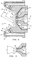
- the nozzle assembly 10 includes a fluid tip 11 and an air cap 12.
- the fluid tip 11 has a central chamber 13 which receives the paint or other fluid to be sprayed.
- a conical seat 15 is located for engagement by a fluid valve needle (not shown), as is well known in the art.
- the seat 15 leads to a fluid discharge orifice 16 which extends through a tubular projection 17 on the fluid tip 11.
- the tubular projection 17 has a flat annular front face 18.
- the seat 15, the orifice 16, the tubular projection 17 and the front face 18 are all coaxial with an axis 19.
- the air cap 12 also is positioned so that an internal air chamber 20 and an atomization air orifice 21 are coaxial with the axis 19.
- the exterior of the fluid tip 11 has a cylindrical rear surface 22.
- a conical surface 23 is located forward of the cylindrical surface 22 and a second, smaller conical surface 24 is located between the conical surface 23 and the tubular projection 17.
- the air cap chamber 20 and orifice 21 have generally the same shape as the fluid tip surfaces.
- the chamber 20 has a cylindrical surface 25 spaced from the cylindrical fluid tip surface 22, a conical surface 26 spaced from the conical surface 23, a conical surface 27 spaced from the conical surface 24, and the cylindrical orifice 21 spaced from the tubular projection 17.
- a flat face 28 separates the air cap surfaces 26 and 27 to constrict the air flow passage towards the orifice 21.
- the fluid tip projection 17 extends completely through the atomization air orifice 21.
- the projection 17 is either flush with a front face 29 on the air cap 12 or projects up to 0.015 inch (0.0381 cm) from the front face 29 to optimize suction.
- a high volume flow of low pressure air is discharged from the chamber 20 through the annular orifice 21 in an annular pattern which surrounds the fluid discharge orifice 16. This creates a reduced pressure or suction in an aspiration zone 30 immediately in front of the orifice 16.
- paint is drawn from the orifice 16 into the aspiration zone 30 where it is atomized and carried forward by the air flow.
- the envelope As the paint is atomized and carried forward, its envelope has a diverging conical shape. It is generally desirable to impart a flat fan shape to the atomized paint envelope. This is achieved by directing one or more pairs of jets of pattern shaping pattern shaping air at diametrically opposite sides of the conical envelope.
- Two air horns 31 extend forward from the front face 29 of the air cap 12. The air horns 31 are spaced from and extend on opposite sides of the atomized paint envelope.
- First and second orifices 32 and 33 are located on each air horn 31. The first orifices 32 are located opposite each other and the second orifices 33 are located opposite each other.
- the orifices 32 have axes 34 which are inclined at equal and opposite angles to the axis 19 and the orifices 33 have axes 35 are inclined at equal and opposite angles to the axis 19.
- the axes 19, 34 and 35 are co-planar.
- the envelope of the atomized paint diverges as it moves away from the fluid discharge orifice 16.
- a face 36 on each air horn 31 is angled to maintain a spacing between the atomized paint and the horns 31, even when the pattern shaping air is turned off Since the atomized paint pattern is larger at as the spacing from the orifice 16 increases, a larger volume of pattern shaping air can be used at a further spacing from the orifice 16. Consequently, the orifices 33 which are spaced further from the orifice 16 are larger than the orifices 32.
- auxiliary orifices 37 are located in the air cap face 29.
- One of the orifices 37 is located between the atomization air orifice 21 and each air horn 31.
- the orifices 37 direct auxiliary air jets parallel to the axis 19 towards the pattern shaping air jets emitted from the orifices 32.
- four additional smaller auxiliary air jet orifices 38 are formed in the air cap surface 29 with one located on opposite sides of each of the two orifices 37.
- Orifices 38 provide an evenly distributed sheet of auxiliary atomization air around the primary atomization air emitted from the orifice 21 to improve consistency of the patterns size and shape.
- the six auxiliary air orifices 37 and 38 help maximize the length of the shaped atomized paint pattern.
- the air streams from the auxiliary holes 37 and 38 inter-act with the pattern shaping air streams from the first horn orifices 32 to cause the width of the pattern shaping air streams to increase before they impact the centre air around the stream of atomized fluid.
- the stream of atomized fluid is then deflected into an elliptical shape before it is hit by the air stream from the second horn orifices 33. This maximizes the pattern length with less tendency to split the pattern when spraying, for example, automotive refinish materials.
- the distance X is 0.268 inch (0.681 cm) and the distance Y is 0.399 inch (1.013 cm).
- the faces 36 of the air horns were directed at an angle of 30° to the axis 19.
- the shaping air orifices 32 had a 0.0595 inch (0.151 cm) diameter and the shaping air orifices 33 had a 0.120 inch (0.305 cm) diameter.
- the air horns 31 were made longer and the distance X was increased to 0.358 inch (0.909 cm) and the distance Y was increased to 0.501 inch (1.273 cm). With the increased spacing, the shaping air orifices 32 could be increased to 0.070 inch (0.178 cm) diameter and the shaping air orifices 33 could be increased to 0.136 inch (0.345 cm) diameter.
- the second air cap was also operated with a fluid tip having a 0.086 inch (0.218 cm) fluid orifice 16
- the paint flow increased up to 240 grams/minute because of the increased suction.
- Both of the first and second air caps included the two auxiliary air orifices 37 having a diameter of 0.040 inch (0.102 cm). However, neither of the first or second air caps 12 included the four auxiliary air orifices 38. As a consequence of the longer air horns 31, the air horns 31 became dirty with paint during spraying.
- a third air cap 12 was produced of similar design to the second air cap, except that four auxiliary air orifices 38 having a diameter of 0.025 inch (0.0635 cm) were added. Further, the fluid orifice 16 was enlarged to 0.110 inch (0.279 cm). With the addition of the four auxiliary air orifices 38 and the enlarged fluid orifice, the fluid flow rate increased to 300 grams/minute. The increased fluid flow was achieved through both moving the pattern shaping orifices 32 at least 0.090 inch (0.227 cm) further from the fluid orifice 16 to create a minimum spacing from the centre of the pattern shaping air orifices 32 to the fluid orifice 16 of 0.35 inch (0.89 cm) and through the addition of the four auxiliary air orifices 38.
- the resulting increased suction in the aspiration zone 30 allowed a larger diameter fluid discharge orifice 16 to further increase fluid flow.
- the reduced turbulence in the atomization air surrounding the aspiration zone 30 also allows the spray gun to operate with a smaller atomization air orifice.
- the reduced atomization air flow allows more effective use of the pattern shaping air from the horns 31 to create a longer pattern length and to help keep the air cap clean.
- the nozzle assembly 10 has improved both the flow rate and the pattern length over prior art suction feed nozzle assemblies for HVLP paint spray guns.
- Fig. 3 shows a modified fluid tip 11' for use with the air cap 12 of Figs. 1 and 2 to provide an increased uniformity particle distribution in the atomized paint.
- the fluid tip 11' has a fluid chamber 13' having a front end 14' and a conical seat 15' identical to the fluid tip 11.
- a fluid discharge orifice 16' has a straight cylindrical section 40 connecting between the seat 15 and an outwardly flaring conical section 41 which opens at the annular front face 18'. It has been found that the size of the flat annular face 18' affects the uniformity of the particle distribution in the atomized paint. An increase in the size can adversely affect the uniformity in an unpredictable manner.
- the size of the face 18' is reduced and the particle distribution uniformity is improved.
- the section 41 is flared at an included angle a of from 28° to 45°.
- the size of the face 18' may be further reduced by providing a chamfer 42 between the outer surface of the tubular projection 17' and the front face 18'.
- the front face 18' of the tubular projection 17' should not be formed into a sharp edge because of the risk of damage.
- the provision of the conical or flared section 41 to the fluid discharge orifice 16' will improve particle distribution uniformity in pressure feed and gravity feed HVLP spray guns. However, the improvement is believed to be greater in a suction feed gun.
Landscapes
- Nozzles (AREA)
- Jet Pumps And Other Pumps (AREA)
- Pressure-Spray And Ultrasonic-Wave- Spray Burners (AREA)
Applications Claiming Priority (2)
| Application Number | Priority Date | Filing Date | Title |
|---|---|---|---|
| US14427993A | 1993-10-28 | 1993-10-28 | |
| US144279 | 1993-10-28 |
Publications (3)
| Publication Number | Publication Date |
|---|---|
| EP0650766A2 true EP0650766A2 (de) | 1995-05-03 |
| EP0650766A3 EP0650766A3 (de) | 1995-09-20 |
| EP0650766B1 EP0650766B1 (de) | 1999-04-07 |
Family
ID=22507875
Family Applications (1)
| Application Number | Title | Priority Date | Filing Date |
|---|---|---|---|
| EP94307747A Expired - Lifetime EP0650766B1 (de) | 1993-10-28 | 1994-10-21 | Durch Ansaugen gespeiste Düse für Niederdruckspritzpistolen |
Country Status (7)
| Country | Link |
|---|---|
| US (1) | US5456414A (de) |
| EP (1) | EP0650766B1 (de) |
| AT (1) | ATE178508T1 (de) |
| CA (1) | CA2132039C (de) |
| DE (1) | DE69417679T2 (de) |
| FI (1) | FI945068A7 (de) |
| NO (1) | NO944094L (de) |
Cited By (21)
| Publication number | Priority date | Publication date | Assignee | Title |
|---|---|---|---|---|
| DE19643621A1 (de) * | 1996-10-22 | 1998-04-30 | Fraunhofer Ges Forschung | Luftkappe für pneumatische Applikationsverfahren und pneumatisches Applikationsverfahren |
| EP0839579A1 (de) * | 1996-11-05 | 1998-05-06 | OFFICINE MECCANICHE A.N.I. S.p.A. | Abmessungen für die Luft- und Flüssigkeitsöffnungen der Düse einer Niederdruckspritzpistole |
| CN105665208A (zh) * | 2016-04-15 | 2016-06-15 | 东北林业大学 | 一种聚脲喷涂喷枪的雾化空气帽 |
| EP3184177A1 (de) * | 2015-12-21 | 2017-06-28 | SATA GmbH & Co. KG | Luftkappe und düsenanordnung für eine spritzpistole und spritzpistole |
| US9782785B2 (en) | 2010-12-02 | 2017-10-10 | Sata Gmbh & Co. Kg | Spray gun and accessories |
| US9782784B2 (en) | 2010-05-28 | 2017-10-10 | Sata Gmbh & Co. Kg | Nozzle head for a spray device |
| CN107626467A (zh) * | 2017-08-30 | 2018-01-26 | 苏州昌田机械设备制造有限公司 | 一种用于金属表面喷涂的喷涂设备 |
| US9878336B2 (en) | 2006-12-05 | 2018-01-30 | Sata Gmbh & Co. Kg | Fluid reservoir for a paint spray gun |
| FR3055817A1 (fr) * | 2016-09-14 | 2018-03-16 | Exel Industries | Buse pour un dispositif d'application d'un produit de revetement et dispositif d'application comprenant une telle buse |
| USD835235S1 (en) | 2014-07-31 | 2018-12-04 | Sata Gmbh & Co. Kg | Paint spray gun |
| US10189037B2 (en) | 2011-06-30 | 2019-01-29 | Sata Gmbh & Co. Kg | Easy-to-clean spray gun, accessories therefor, and mounting and dismounting methods |
| US10471449B2 (en) | 2016-08-19 | 2019-11-12 | Sata Gmbh & Co. Kg | Air cap arrangement and spray gun |
| US10702879B2 (en) | 2014-07-31 | 2020-07-07 | Sata Gmbh & Co. Kg | Spray gun manufacturing method, spray gun, spray gun body and cover |
| US10835911B2 (en) | 2016-08-19 | 2020-11-17 | Sata Gmbh & Co. Kg | Trigger for a spray gun and spray gun having same |
| US11141747B2 (en) | 2015-05-22 | 2021-10-12 | Sata Gmbh & Co. Kg | Nozzle arrangement for a spray gun |
| US11801521B2 (en) | 2018-08-01 | 2023-10-31 | Sata Gmbh & Co. Kg | Main body for a spray gun, spray guns, spray gun set, method for producing a main body for a spray gun and method for converting a spray gun |
| US11826771B2 (en) | 2018-08-01 | 2023-11-28 | Sata Gmbh & Co. Kg | Set of nozzles for a spray gun, spray gun system, method for embodying a nozzle module, method for selecting a nozzle module from a set of nozzles for a paint job, selection system and computer program product |
| US11865558B2 (en) | 2018-08-01 | 2024-01-09 | Sata Gmbh & Co. Kg | Nozzle for a spray gun, nozzle set for a spray gun, spray guns and methods for producing a nozzle for a spray gun |
| US12097519B2 (en) | 2020-09-11 | 2024-09-24 | Sata Gmbh & Co. Kg | Sealing element for sealing a transition between a spray gun body and an attachment of a spray gun, attachment, in particular a paint nozzle arrangement for a spray gun and a spray gun, in particular a paint spray gun |
| US12515230B2 (en) | 2018-09-10 | 2026-01-06 | Sata Gmbh & Co. Kg | Paint gun, material application system, and method for operating same |
| US12594566B2 (en) | 2020-03-06 | 2026-04-07 | Sata Gmbh & Co. Kg | Spray gun, in particular a pressurized air atomization paint spray gun, in particular a hand-held pressurized air atomization paint spray gun |
Families Citing this family (35)
| Publication number | Priority date | Publication date | Assignee | Title |
|---|---|---|---|---|
| GB2283927B (en) * | 1993-11-22 | 1998-01-21 | Itw Ltd | An improved spray nozzle |
| US20050284957A1 (en) * | 2002-09-23 | 2005-12-29 | Spraying Systems Co. | External mix air atomizing spray nozzle assembly |
| WO2004035222A2 (en) * | 2002-10-15 | 2004-04-29 | Spraying Systems, Co. | External mix air assisted spray nozzle assembly |
| USD484411S1 (en) | 2002-10-15 | 2003-12-30 | Spraying Systems Co. | Liquid spray nozzle air directing cap |
| SE525307C2 (sv) * | 2003-06-30 | 2005-01-25 | Baldwin Jimek Ab | Lufthuv |
| FR2872717B1 (fr) * | 2004-07-12 | 2006-09-15 | Itw Surfaces & Finitions Sa | Pistolet de pulverisation automatique comprenant un corps de pulverisation monte sur une embase d'alimentation |
| CA2717749C (en) | 2008-03-12 | 2014-06-03 | Jeffrey D. Fox | Disposable spray gun cartridge |
| CN101609190B (zh) * | 2008-06-20 | 2011-09-28 | 鸿富锦精密工业(深圳)有限公司 | 压棒 |
| CN102355956A (zh) | 2009-01-26 | 2012-02-15 | 3M创新有限公司 | 液体喷枪、喷枪平台和喷头组件 |
| US20100224703A1 (en) * | 2009-03-09 | 2010-09-09 | Illinois Tool Works Inc. | Pneumatic Atomization Nozzle for Web Moistening |
| US9186881B2 (en) | 2009-03-09 | 2015-11-17 | Illinois Tool Works Inc. | Thermally isolated liquid supply for web moistening |
| US8979004B2 (en) * | 2009-03-09 | 2015-03-17 | Illinois Tool Works Inc. | Pneumatic atomization nozzle for web moistening |
| US20100224122A1 (en) * | 2009-03-09 | 2010-09-09 | Illinois Tool Works Inc. | Low pressure regulation for web moistening systems |
| DE102009032399A1 (de) | 2009-07-08 | 2011-01-13 | Sata Gmbh & Co. Kg | Farbspritzpistole |
| JP6110313B2 (ja) | 2011-02-09 | 2017-04-05 | スリーエム イノベイティブ プロパティズ カンパニー | 液体スプレーガン用のノズルチップ及びスプレーヘッドアセンブリ |
| BR112014001936A2 (pt) | 2011-07-28 | 2017-02-21 | 3M Innovative Properties Co | conjunto de cabeça de aspersão com bocal/tampa de ar integrada para uma pistola de aspersão de líquido |
| RU2574755C2 (ru) | 2011-10-12 | 2016-02-10 | 3М Инновейтив Пропертиз Компани | Агрегаты головки распылителя для жидкостных пистолетов-распылителей |
| MX370998B (es) | 2012-03-06 | 2020-01-13 | 3M Innovative Properties Co | Pistola pulverizadora que tiene pasaje de sobrecompresion interno. |
| JP6444297B2 (ja) | 2012-03-23 | 2018-12-26 | スリーエム イノベイティブ プロパティズ カンパニー | 分割不能なノズル付きスプレーガンバレル |
| JP5787407B2 (ja) | 2012-08-03 | 2015-09-30 | アネスト岩田株式会社 | スプレーガン |
| JP5787408B2 (ja) | 2012-08-08 | 2015-09-30 | アネスト岩田株式会社 | スプレーガン |
| JP5787409B2 (ja) | 2012-08-10 | 2015-09-30 | アネスト岩田株式会社 | スプレーガン |
| JP5787411B2 (ja) | 2012-08-31 | 2015-09-30 | アネスト岩田株式会社 | スプレーガン |
| JP5787410B2 (ja) | 2012-08-31 | 2015-09-30 | アネスト岩田株式会社 | スプレーガン |
| US10493473B2 (en) | 2013-07-15 | 2019-12-03 | 3M Innovative Properties Company | Air caps with face geometry inserts for liquid spray guns |
| DE202013105779U1 (de) | 2013-12-18 | 2015-03-19 | Sata Gmbh & Co. Kg | Luftdüsenabschluss für eine Lackierpistole |
| US9302278B2 (en) * | 2014-05-29 | 2016-04-05 | Tsung Mao Industrial Co., Ltd. | Nozzle of spray gun |
| AU2015275044B2 (en) | 2014-06-10 | 2018-11-01 | 3M Innovative Properties Company | Nozzle assembly with external baffles |
| USD768820S1 (en) | 2014-09-03 | 2016-10-11 | Sata Gmbh & Co. Kg | Paint spray gun with pattern |
| JP6908215B2 (ja) * | 2015-10-02 | 2021-07-21 | スプレイング システムズ カンパニー | 加圧空気アシスト式フルコーンスプレーノズル組立体 |
| CN107511277B (zh) * | 2016-06-17 | 2022-12-13 | 韩帅 | 自吸式节能喷头 |
| EP3996924A4 (de) | 2019-07-11 | 2023-07-19 | The Regents of the University of Michigan | Aerosoldrucken von spezialflüssigkeiten |
| IT202000000761U1 (it) * | 2020-02-18 | 2021-08-18 | Barnini S R L | Testina per pistola di verniciatura |
| US11820583B2 (en) * | 2020-12-17 | 2023-11-21 | S. C. Johnson & Son, Inc. | Double nozzle overcap assembly |
| USD1033225S1 (en) | 2021-12-13 | 2024-07-02 | S. C. Johnson & Son, Inc. | Actuator overcap |
Family Cites Families (22)
| Publication number | Priority date | Publication date | Assignee | Title |
|---|---|---|---|---|
| US2511626A (en) * | 1942-04-17 | 1950-06-13 | Sherwin Williams Co | Apparatus for producing spatter finish coatings |
| GB676600A (en) * | 1949-12-10 | 1952-07-30 | Atlas Diesel Ab | Improvements in nozzles for spraying paint air jets or the like |
| US3032277A (en) * | 1959-07-27 | 1962-05-01 | Sherwin Williams Co | Spray gun for multicolor paints |
| US3072346A (en) * | 1961-09-29 | 1963-01-08 | Spraying Systems Co | Spray nozzle |
| US4343433A (en) * | 1977-09-29 | 1982-08-10 | Ppg Industries, Inc. | Internal-atomizing spray head with secondary annulus suitable for use with induction charging electrode |
| US4544100A (en) * | 1983-10-06 | 1985-10-01 | Nordson Corporation | Liquid spray gun having quick change pattern control |
| FR2595059B1 (fr) * | 1986-02-28 | 1988-06-17 | Sames Sa | Dispositif de pulverisation de liquide |
| DE3709543C2 (de) * | 1987-03-24 | 1996-06-05 | Wagner Gmbh J | Vorrichtung zum Zerstäuben einer Flüssigkeit |
| GB8802130D0 (en) * | 1988-02-01 | 1988-03-02 | Devilbiss Co | Spraygun |
| US5078322A (en) * | 1988-10-24 | 1992-01-07 | Wagner Spray Tech Corporation | Low pressure high volume spray gun |
| US4911365A (en) * | 1989-01-26 | 1990-03-27 | James E. Hynds | Spray gun having a fanning air turbine mechanism |
| US5064119A (en) * | 1989-02-03 | 1991-11-12 | Binks Manufacturing Company | High-volume low pressure air spray gun |
| US5165605A (en) * | 1989-03-30 | 1992-11-24 | Iwata Air Compressor Mfg. Co., Ltd. | Low pressure air atomizing spray gun |
| EP0408786B1 (de) * | 1989-07-19 | 1993-08-25 | SATA-FARBSPRITZTECHNIK GmbH & Co. | Düsenkopf |
| DE8911932U1 (de) * | 1989-10-06 | 1990-01-18 | Bersch & Fratscher GmbH, 8757 Karlstein | Farbspritzpistole |
| US5074466A (en) * | 1990-01-16 | 1991-12-24 | Binks Manufacturing Company | Fluid valve stem for air spray gun |
| JPH0724796B2 (ja) * | 1990-05-11 | 1995-03-22 | 岩田塗装機工業株式会社 | 低圧微粒化エアスプレーガン |
| US5090623A (en) * | 1990-12-06 | 1992-02-25 | Ransburg Corporation | Paint spray gun |
| US5180104A (en) * | 1991-02-20 | 1993-01-19 | Binks Manufacturing Company | Hydraulically assisted high volume low pressure air spray gun |
| US5209405A (en) * | 1991-04-19 | 1993-05-11 | Ransburg Corporation | Baffle for hvlp paint spray gun |
| EP0609005A1 (de) * | 1993-01-27 | 1994-08-03 | ITW Limited | Luftkappe für Sprühpistolen |
| US5344078A (en) * | 1993-04-22 | 1994-09-06 | Ransburg Corporation | Nozzle assembly for HVLP spray gun |
-
1994
- 1994-07-15 US US08/275,532 patent/US5456414A/en not_active Expired - Lifetime
- 1994-09-14 CA CA002132039A patent/CA2132039C/en not_active Expired - Fee Related
- 1994-10-21 DE DE69417679T patent/DE69417679T2/de not_active Expired - Fee Related
- 1994-10-21 EP EP94307747A patent/EP0650766B1/de not_active Expired - Lifetime
- 1994-10-21 AT AT94307747T patent/ATE178508T1/de not_active IP Right Cessation
- 1994-10-27 NO NO944094A patent/NO944094L/no unknown
- 1994-10-27 FI FI945068A patent/FI945068A7/fi not_active Application Discontinuation
Cited By (24)
| Publication number | Priority date | Publication date | Assignee | Title |
|---|---|---|---|---|
| DE19643621B4 (de) * | 1996-10-22 | 2004-02-26 | Fraunhofer-Gesellschaft zur Förderung der angewandten Forschung e.V. | Luftkappe für pneumatische Lackspritzvorrichtungen und pneumatisches Aufbringverfahren |
| DE19643621A1 (de) * | 1996-10-22 | 1998-04-30 | Fraunhofer Ges Forschung | Luftkappe für pneumatische Applikationsverfahren und pneumatisches Applikationsverfahren |
| EP0839579A1 (de) * | 1996-11-05 | 1998-05-06 | OFFICINE MECCANICHE A.N.I. S.p.A. | Abmessungen für die Luft- und Flüssigkeitsöffnungen der Düse einer Niederdruckspritzpistole |
| US9878336B2 (en) | 2006-12-05 | 2018-01-30 | Sata Gmbh & Co. Kg | Fluid reservoir for a paint spray gun |
| US9782784B2 (en) | 2010-05-28 | 2017-10-10 | Sata Gmbh & Co. Kg | Nozzle head for a spray device |
| US9782785B2 (en) | 2010-12-02 | 2017-10-10 | Sata Gmbh & Co. Kg | Spray gun and accessories |
| US10189037B2 (en) | 2011-06-30 | 2019-01-29 | Sata Gmbh & Co. Kg | Easy-to-clean spray gun, accessories therefor, and mounting and dismounting methods |
| US10702879B2 (en) | 2014-07-31 | 2020-07-07 | Sata Gmbh & Co. Kg | Spray gun manufacturing method, spray gun, spray gun body and cover |
| USD835235S1 (en) | 2014-07-31 | 2018-12-04 | Sata Gmbh & Co. Kg | Paint spray gun |
| US11141747B2 (en) | 2015-05-22 | 2021-10-12 | Sata Gmbh & Co. Kg | Nozzle arrangement for a spray gun |
| EP3184177A1 (de) * | 2015-12-21 | 2017-06-28 | SATA GmbH & Co. KG | Luftkappe und düsenanordnung für eine spritzpistole und spritzpistole |
| CN106944279A (zh) * | 2015-12-21 | 2017-07-14 | 萨塔有限两合公司 | 用于喷枪的空气帽和喷嘴组件以及喷枪 |
| US10464076B2 (en) | 2015-12-21 | 2019-11-05 | Sata Gmbh & Co. Kg | Air cap and nozzle assembly for a spray gun, and spray gun |
| CN105665208A (zh) * | 2016-04-15 | 2016-06-15 | 东北林业大学 | 一种聚脲喷涂喷枪的雾化空气帽 |
| US10835911B2 (en) | 2016-08-19 | 2020-11-17 | Sata Gmbh & Co. Kg | Trigger for a spray gun and spray gun having same |
| US10471449B2 (en) | 2016-08-19 | 2019-11-12 | Sata Gmbh & Co. Kg | Air cap arrangement and spray gun |
| FR3055817A1 (fr) * | 2016-09-14 | 2018-03-16 | Exel Industries | Buse pour un dispositif d'application d'un produit de revetement et dispositif d'application comprenant une telle buse |
| CN107626467A (zh) * | 2017-08-30 | 2018-01-26 | 苏州昌田机械设备制造有限公司 | 一种用于金属表面喷涂的喷涂设备 |
| US11801521B2 (en) | 2018-08-01 | 2023-10-31 | Sata Gmbh & Co. Kg | Main body for a spray gun, spray guns, spray gun set, method for producing a main body for a spray gun and method for converting a spray gun |
| US11826771B2 (en) | 2018-08-01 | 2023-11-28 | Sata Gmbh & Co. Kg | Set of nozzles for a spray gun, spray gun system, method for embodying a nozzle module, method for selecting a nozzle module from a set of nozzles for a paint job, selection system and computer program product |
| US11865558B2 (en) | 2018-08-01 | 2024-01-09 | Sata Gmbh & Co. Kg | Nozzle for a spray gun, nozzle set for a spray gun, spray guns and methods for producing a nozzle for a spray gun |
| US12515230B2 (en) | 2018-09-10 | 2026-01-06 | Sata Gmbh & Co. Kg | Paint gun, material application system, and method for operating same |
| US12594566B2 (en) | 2020-03-06 | 2026-04-07 | Sata Gmbh & Co. Kg | Spray gun, in particular a pressurized air atomization paint spray gun, in particular a hand-held pressurized air atomization paint spray gun |
| US12097519B2 (en) | 2020-09-11 | 2024-09-24 | Sata Gmbh & Co. Kg | Sealing element for sealing a transition between a spray gun body and an attachment of a spray gun, attachment, in particular a paint nozzle arrangement for a spray gun and a spray gun, in particular a paint spray gun |
Also Published As
| Publication number | Publication date |
|---|---|
| FI945068A0 (fi) | 1994-10-27 |
| CA2132039C (en) | 2000-05-16 |
| NO944094L (no) | 1995-05-02 |
| DE69417679D1 (de) | 1999-05-12 |
| US5456414A (en) | 1995-10-10 |
| DE69417679T2 (de) | 1999-07-29 |
| FI945068A7 (fi) | 1995-04-29 |
| CA2132039A1 (en) | 1995-04-29 |
| NO944094D0 (no) | 1994-10-27 |
| ATE178508T1 (de) | 1999-04-15 |
| EP0650766A3 (de) | 1995-09-20 |
| EP0650766B1 (de) | 1999-04-07 |
Similar Documents
| Publication | Publication Date | Title |
|---|---|---|
| EP0650766B1 (de) | Durch Ansaugen gespeiste Düse für Niederdruckspritzpistolen | |
| US5344078A (en) | Nozzle assembly for HVLP spray gun | |
| US5209405A (en) | Baffle for hvlp paint spray gun | |
| EP0075018B1 (de) | Zerstäubungsdüse | |
| US5170941A (en) | Premixing-type spray gun | |
| US5074466A (en) | Fluid valve stem for air spray gun | |
| EP0705644A1 (de) | Sprühdüse mit interner Luftmischung | |
| US3734406A (en) | Method and apparatus for producing a flat fan paint spray pattern | |
| EP0717095A2 (de) | Strahldüse für die Anwendung im katalytischen Wirbelschicht-Krackverfahren | |
| US4555059A (en) | Flow-amplifying liquid-atomizing nozzle | |
| US4232824A (en) | Method and apparatus for the pneumatic spraying of liquid products | |
| JP2002096003A (ja) | 改良型空気式スプレーノズル | |
| JPH08117649A (ja) | 塗料スプレーガンのノズル装置 | |
| JPH0418952A (ja) | 低圧微粒化エアスプレーガン | |
| US4273287A (en) | Atomizer head for paint spray guns | |
| US20240100550A1 (en) | Spray gun nozzle | |
| JP7436161B2 (ja) | 流体チップ | |
| US5295628A (en) | Discharge nozzle for media | |
| CN108031579A (zh) | 喷枪及其枪头、空气喷涂装置 | |
| EP0411830B1 (de) | Pneumatische Niederdruckspritzpistole | |
| US5397058A (en) | Low pressure fumeless spray gun | |
| JPH04247252A (ja) | 低圧広角パターンスプレーガン | |
| JPH0330853A (ja) | 噴霧装置 | |
| JP3359771B2 (ja) | 低圧微粒化スプレーガン | |
| JP2024155181A (ja) | ミストノズル |
Legal Events
| Date | Code | Title | Description |
|---|---|---|---|
| PUAI | Public reference made under article 153(3) epc to a published international application that has entered the european phase |
Free format text: ORIGINAL CODE: 0009012 |
|
| AK | Designated contracting states |
Kind code of ref document: A2 Designated state(s): AT BE CH DE DK ES FR GB GR IE IT LI LU NL PT SE |
|
| PUAL | Search report despatched |
Free format text: ORIGINAL CODE: 0009013 |
|
| AK | Designated contracting states |
Kind code of ref document: A3 Designated state(s): AT BE CH DE DK ES FR GB GR IE IT LI LU NL PT SE |
|
| 17P | Request for examination filed |
Effective date: 19960301 |
|
| 17Q | First examination report despatched |
Effective date: 19970620 |
|
| GRAG | Despatch of communication of intention to grant |
Free format text: ORIGINAL CODE: EPIDOS AGRA |
|
| GRAG | Despatch of communication of intention to grant |
Free format text: ORIGINAL CODE: EPIDOS AGRA |
|
| GRAH | Despatch of communication of intention to grant a patent |
Free format text: ORIGINAL CODE: EPIDOS IGRA |
|
| GRAH | Despatch of communication of intention to grant a patent |
Free format text: ORIGINAL CODE: EPIDOS IGRA |
|
| GRAA | (expected) grant |
Free format text: ORIGINAL CODE: 0009210 |
|
| AK | Designated contracting states |
Kind code of ref document: B1 Designated state(s): AT BE CH DE DK ES FR GB GR IE IT LI LU NL PT SE |
|
| PG25 | Lapsed in a contracting state [announced via postgrant information from national office to epo] |
Ref country code: SE Free format text: THE PATENT HAS BEEN ANNULLED BY A DECISION OF A NATIONAL AUTHORITY Effective date: 19990407 Ref country code: NL Free format text: LAPSE BECAUSE OF FAILURE TO SUBMIT A TRANSLATION OF THE DESCRIPTION OR TO PAY THE FEE WITHIN THE PRESCRIBED TIME-LIMIT Effective date: 19990407 Ref country code: LI Free format text: LAPSE BECAUSE OF FAILURE TO SUBMIT A TRANSLATION OF THE DESCRIPTION OR TO PAY THE FEE WITHIN THE PRESCRIBED TIME-LIMIT Effective date: 19990407 Ref country code: GR Free format text: LAPSE BECAUSE OF NON-PAYMENT OF DUE FEES Effective date: 19990407 Ref country code: ES Free format text: THE PATENT HAS BEEN ANNULLED BY A DECISION OF A NATIONAL AUTHORITY Effective date: 19990407 Ref country code: CH Free format text: LAPSE BECAUSE OF FAILURE TO SUBMIT A TRANSLATION OF THE DESCRIPTION OR TO PAY THE FEE WITHIN THE PRESCRIBED TIME-LIMIT Effective date: 19990407 Ref country code: BE Free format text: LAPSE BECAUSE OF FAILURE TO SUBMIT A TRANSLATION OF THE DESCRIPTION OR TO PAY THE FEE WITHIN THE PRESCRIBED TIME-LIMIT Effective date: 19990407 Ref country code: AT Free format text: LAPSE BECAUSE OF FAILURE TO SUBMIT A TRANSLATION OF THE DESCRIPTION OR TO PAY THE FEE WITHIN THE PRESCRIBED TIME-LIMIT Effective date: 19990407 |
|
| REF | Corresponds to: |
Ref document number: 178508 Country of ref document: AT Date of ref document: 19990415 Kind code of ref document: T |
|
| REG | Reference to a national code |
Ref country code: CH Ref legal event code: EP |
|
| REG | Reference to a national code |
Ref country code: IE Ref legal event code: FG4D |
|
| REF | Corresponds to: |
Ref document number: 69417679 Country of ref document: DE Date of ref document: 19990512 |
|
| ET | Fr: translation filed | ||
| PG25 | Lapsed in a contracting state [announced via postgrant information from national office to epo] |
Ref country code: PT Free format text: LAPSE BECAUSE OF FAILURE TO SUBMIT A TRANSLATION OF THE DESCRIPTION OR TO PAY THE FEE WITHIN THE PRESCRIBED TIME-LIMIT Effective date: 19990707 Ref country code: DK Free format text: LAPSE BECAUSE OF FAILURE TO SUBMIT A TRANSLATION OF THE DESCRIPTION OR TO PAY THE FEE WITHIN THE PRESCRIBED TIME-LIMIT Effective date: 19990707 |
|
| NLV1 | Nl: lapsed or annulled due to failure to fulfill the requirements of art. 29p and 29m of the patents act | ||
| REG | Reference to a national code |
Ref country code: CH Ref legal event code: PL |
|
| PG25 | Lapsed in a contracting state [announced via postgrant information from national office to epo] |
Ref country code: LU Free format text: LAPSE BECAUSE OF NON-PAYMENT OF DUE FEES Effective date: 19991021 |
|
| PLBE | No opposition filed within time limit |
Free format text: ORIGINAL CODE: 0009261 |
|
| STAA | Information on the status of an ep patent application or granted ep patent |
Free format text: STATUS: NO OPPOSITION FILED WITHIN TIME LIMIT |
|
| PGFP | Annual fee paid to national office [announced via postgrant information from national office to epo] |
Ref country code: IE Payment date: 20000229 Year of fee payment: 6 |
|
| 26N | No opposition filed | ||
| PG25 | Lapsed in a contracting state [announced via postgrant information from national office to epo] |
Ref country code: IE Free format text: LAPSE BECAUSE OF NON-PAYMENT OF DUE FEES Effective date: 20001023 |
|
| REG | Reference to a national code |
Ref country code: IE Ref legal event code: MM4A |
|
| PGFP | Annual fee paid to national office [announced via postgrant information from national office to epo] |
Ref country code: FR Payment date: 20011002 Year of fee payment: 8 |
|
| PGFP | Annual fee paid to national office [announced via postgrant information from national office to epo] |
Ref country code: GB Payment date: 20011004 Year of fee payment: 8 Ref country code: DE Payment date: 20011004 Year of fee payment: 8 |
|
| REG | Reference to a national code |
Ref country code: GB Ref legal event code: IF02 |
|
| PG25 | Lapsed in a contracting state [announced via postgrant information from national office to epo] |
Ref country code: GB Free format text: LAPSE BECAUSE OF NON-PAYMENT OF DUE FEES Effective date: 20021021 |
|
| PG25 | Lapsed in a contracting state [announced via postgrant information from national office to epo] |
Ref country code: DE Free format text: LAPSE BECAUSE OF NON-PAYMENT OF DUE FEES Effective date: 20030501 |
|
| GBPC | Gb: european patent ceased through non-payment of renewal fee |
Effective date: 20021021 |
|
| PG25 | Lapsed in a contracting state [announced via postgrant information from national office to epo] |
Ref country code: FR Free format text: LAPSE BECAUSE OF NON-PAYMENT OF DUE FEES Effective date: 20030630 |
|
| REG | Reference to a national code |
Ref country code: FR Ref legal event code: ST |
|
| PG25 | Lapsed in a contracting state [announced via postgrant information from national office to epo] |
Ref country code: IT Free format text: LAPSE BECAUSE OF NON-PAYMENT OF DUE FEES;WARNING: LAPSES OF ITALIAN PATENTS WITH EFFECTIVE DATE BEFORE 2007 MAY HAVE OCCURRED AT ANY TIME BEFORE 2007. THE CORRECT EFFECTIVE DATE MAY BE DIFFERENT FROM THE ONE RECORDED. Effective date: 20051021 |