EP0650769A1 - Configuration de filière d'enduction en forme de fente - Google Patents
Configuration de filière d'enduction en forme de fente Download PDFInfo
- Publication number
- EP0650769A1 EP0650769A1 EP94115809A EP94115809A EP0650769A1 EP 0650769 A1 EP0650769 A1 EP 0650769A1 EP 94115809 A EP94115809 A EP 94115809A EP 94115809 A EP94115809 A EP 94115809A EP 0650769 A1 EP0650769 A1 EP 0650769A1
- Authority
- EP
- European Patent Office
- Prior art keywords
- slot
- coating
- hot melt
- coating die
- die
- Prior art date
- Legal status (The legal status is an assumption and is not a legal conclusion. Google has not performed a legal analysis and makes no representation as to the accuracy of the status listed.)
- Granted
Links
- 238000000576 coating method Methods 0.000 title claims abstract description 156
- 239000011248 coating agent Substances 0.000 title claims abstract description 153
- 239000012943 hotmelt Substances 0.000 claims abstract description 62
- 239000002966 varnish Substances 0.000 claims abstract description 60
- 239000000463 material Substances 0.000 claims abstract description 28
- 239000000758 substrate Substances 0.000 claims abstract description 26
- 239000002245 particle Substances 0.000 claims abstract description 23
- 238000009825 accumulation Methods 0.000 abstract description 2
- 238000000034 method Methods 0.000 description 7
- 238000010276 construction Methods 0.000 description 4
- 230000001681 protective effect Effects 0.000 description 4
- 239000004831 Hot glue Substances 0.000 description 3
- 230000008859 change Effects 0.000 description 3
- 238000004806 packaging method and process Methods 0.000 description 3
- 239000004698 Polyethylene Substances 0.000 description 2
- 229910001315 Tool steel Inorganic materials 0.000 description 2
- 239000000853 adhesive Substances 0.000 description 2
- 230000001070 adhesive effect Effects 0.000 description 2
- DQXBYHZEEUGOBF-UHFFFAOYSA-N but-3-enoic acid;ethene Chemical compound C=C.OC(=O)CC=C DQXBYHZEEUGOBF-UHFFFAOYSA-N 0.000 description 2
- 239000005038 ethylene vinyl acetate Substances 0.000 description 2
- 239000007788 liquid Substances 0.000 description 2
- 238000012986 modification Methods 0.000 description 2
- 230000004048 modification Effects 0.000 description 2
- 229920001200 poly(ethylene-vinyl acetate) Polymers 0.000 description 2
- -1 polyethylene Polymers 0.000 description 2
- 229920000573 polyethylene Polymers 0.000 description 2
- VYZAMTAEIAYCRO-UHFFFAOYSA-N Chromium Chemical compound [Cr] VYZAMTAEIAYCRO-UHFFFAOYSA-N 0.000 description 1
- XUIMIQQOPSSXEZ-UHFFFAOYSA-N Silicon Chemical compound [Si] XUIMIQQOPSSXEZ-UHFFFAOYSA-N 0.000 description 1
- 238000005299 abrasion Methods 0.000 description 1
- 230000004888 barrier function Effects 0.000 description 1
- 230000001143 conditioned effect Effects 0.000 description 1
- 230000008878 coupling Effects 0.000 description 1
- 238000010168 coupling process Methods 0.000 description 1
- 238000005859 coupling reaction Methods 0.000 description 1
- 230000006866 deterioration Effects 0.000 description 1
- 238000006073 displacement reaction Methods 0.000 description 1
- 238000001125 extrusion Methods 0.000 description 1
- 239000011888 foil Substances 0.000 description 1
- 238000007757 hot melt coating Methods 0.000 description 1
- 235000019645 odor Nutrition 0.000 description 1
- 229910052710 silicon Inorganic materials 0.000 description 1
- 239000010703 silicon Substances 0.000 description 1
- 239000007787 solid Substances 0.000 description 1
Images


Classifications
-
- B—PERFORMING OPERATIONS; TRANSPORTING
- B05—SPRAYING OR ATOMISING IN GENERAL; APPLYING FLUENT MATERIALS TO SURFACES, IN GENERAL
- B05C—APPARATUS FOR APPLYING FLUENT MATERIALS TO SURFACES, IN GENERAL
- B05C5/00—Apparatus in which liquid or other fluent material is projected, poured or allowed to flow on to the surface of the work
- B05C5/02—Apparatus in which liquid or other fluent material is projected, poured or allowed to flow on to the surface of the work the liquid or other fluent material being discharged through an outlet orifice by pressure, e.g. from an outlet device in contact or almost in contact, with the work
- B05C5/0254—Coating heads with slot-shaped outlet
Definitions
- the present invention relates generally to a slot coating die for applying a coating of hot melt material to a moving substrate, and particularly to a slot coating die for applying a substantially streakless coating of hot melt varnish to a web of printed label stock.
- the Nordson model EP-51-2 slot coating die is believed to be effective for applying a substantially streakless coating of hot melt varnish to a web of moving label stock for significant periods of time.
- the slot coating die has upper and lower lips and a slot formed between the upper and lower lips.
- the hot melt varnish is extruded through the slot and onto the printed side of the web of printed label stock.
- the upper lip has a distal edge that functions as a doctor blade to wipe the varnish coating to a substantially smooth, streakless state as the web of printed label stock leaves the slot coating die.
- the present invention discloses an improved configuration for a slot coating die, to further enhance its ability to apply a substantially streakless coating of a hot melt material (e.g., hot melt varnish) to a moving substrate such as a web of printed label stock.
- a hot melt material e.g., hot melt varnish
- the hot melt varnish is extruded through the slot (in a direction which is generally perpendicular to the web) and onto the web.
- the distal edge of the upper lip has a relatively sharp (knife-like) configuration, and is located closely adjacent the web, in order to wipe (or scrape) the coating to a substantially smooth, streakless state.
- small particles in the varnish may accumulate near the distal edge of the upper lip. Those particles, if not periodically removed, could cause streaking of the coating. In order to remove the particles, it is necessary to interrupt the coating operation, and to back the slot coating die away from the substrate, to clear such particles.
- the present invention provides a slot coating die specially configured to (i) apply a substantially smooth, streakless coating of a hot melt material to a moving substrate, and (ii) allow small particles in the hot melt material to be released from the coating die and the moving substrate in a manner designed to minimize (or eliminate) the need to interrupt the coating process to clean such particles from the coating die and to avoid streaking of the coating.
- the coating die has an upper lip, a lower lip, and a slot disposed between the upper and lower lips.
- the substrate moves progressively past the coating die (i.e., the substrate moves progressively past the lower lip, the slot, and the upper lip of the coating die).
- a layer of hot melt material e.g., hot melt varnish
- the upper lip is configured to (i) at least partially guide the hot melt material to flow in the direction of movement of the substrate, (ii) gently wipe the hot melt material to a substantially smooth state as the substrate moves progressively past the coating die, and (iii) enable small particles in the coating material to be released from the slot coating die in a manner designed to avoid accumulation of those particles in the coating die and to avoid streaking of the coating.
- the upper lip of the slot coating die has a front face which is configured to define (i) a wiping surface, (ii) a relief surface extending between the slot and the wiping surface, and (iii) a release surface which extends beyond the wiping surface and curves away from the moving substrate.
- the relief surface and the wiping surface are configured to (i) at least partially guide coating material extruded through the slot in the direction of movement of the substrate and (ii) gently wipe the coating to a substantially smooth state.
- the release surface is configured to enable small particles in the hot melt material be gently released from the slot coating die. Those particles may remain as relatively harmless specks on the coating, but since they do not accumulate in the slot coating die, they are unlikely to cause streaking of the coating.
- a slot coating die according to the present invention is particularly useful in applying a coating of hot melt varnish to a web of printed label stock, in a system according to application Serial No. 08/005,237 filed January 15, 1993 for "System and Method for Applying a Desired, Protective Finish to Printed Label Stock".
- a slot coating die according to the present invention is particularly useful in a system for applying a hot melt varnish to a web of printed label stock.
- Application Serial No. 08/005,237 filed January 15, 1993 entitled “System and Method for Applying a Desired, Protective Finish to Printed Label Stock", and assigned to the assignee of the present invention, discloses a printed label coating system which can advantageously utilize a slot coating die according to the present invention, and that application is incorporated herein by reference.
- a label coating station 10 includes a slot coating die 12 which is adapted to apply a coating of hot melt varnish to a web 14 of printed label stock.
- a transfer roll 16 engages the unprinted side of the web 14 of printed label stock, and carries the web 14 of printed label stock at a relatively constant speed past the slot coating die 12.
- hot melt varnish is extruded through the slot coating die 12 and applied as a coating 15 ( Figure 4) to the printed side of the web 14 of printed label stock.
- the slot coating die 12 is configured in accordance with the present invention and oriented relative to the transfer roll 16 such that a substantially streakless coating of hot melt varnish is applied to the printed side of the web 14 being moved by the transfer roll 16 past the slot coating die 12.
- the label coating station 10 also includes (i) a hot melt applicator tank 18 in which the varnish is melted to a substantially liquid (molten) state, (ii) a positive displacement, metering gear pump 20 which is located in the manifold of tank 18 and which pumps a metered amount of the melted varnish from the hot melt applicator tank 18, and (iii) a flexible conduit 22 which directs the molten varnish to the slot coating die 12.
- the metering gear pump 20 can be driven at a substantially constant speed, to pump a metered amount of molten varnish, at a substantially constant flow rate, to the slot coating die 12.
- the speed of the metering gear pump 20 can be selectively changed, to change the rate of flow of varnish to the slot coating die 12.
- a metering device (not shown), of a type which is well known for metering hot melt adhesives, can be placed in the flexible conduit 22 which directs the molten varnish to the slot coating die 12, to further meter the amount of molten varnish directed to the slot coating die 12.
- the hot melt applicator tank 20 comprises a Nordson Model 6000 hot melt applicator tank, which is a known type of hot melt applicator tank for use with hot melt adhesives.
- a combined drum melter/drum unloader 24, also of known construction for use with hot melt adhesives may be provided, if desired, for feeding a supply of the hot melt varnish from a storage drum (not shown) to the hot melt applicator tank 18.
- the thickness of the coating 15 of hot melt varnish applied to the web 14 is determined by factors such as (i) the flow rate of varnish from the metering gear pump 20 to the slot coating die 12, (ii) the speed at which the web 14 is moved past the slot coating die 12, and (iii) the spacing between the slot coating die 12 and the web 14.
- the thickness of the coating 15 of varnish can be readily adjusted by changing (i) the flow rate of varnish from the metering gear pump 20 to the slot coating die 12, (ii) the speed at which the web 14 is moved past the slot coating die 12, and to a lesser extent (depending upon the porosity of the web), (iii) the spacing between the slot coating die 12 and the web 14.
- the coating 15 of hot melt varnish is applied to web 14, the coating is processed in accordance with the system and method of application Serial No. 08/005,237, filed January 15, 1993, and entitled "System and Method for Applying a Desired, Protective Finish to Printed Label Stock".
- the web 14 is wrapped substantially about the transfer roll 16, and is transferred by the transfer roll 16 from the slot coating die 12 through a working station 26 at which the coating of varnish is worked to a smooth, glossy finish.
- the web 14 is then transferred to a finishing station 28 at which the glossy finish is fixed in the coating of varnish and the web is conditioned to a state in which it can be processed as finished label stock.
- the coating of varnish (i) provides a desired glossy finish to the web of printed label stock, (ii) protects the web of printed label stock from damage or deterioration from ambient conditions, and (iii) protects the web of printed label stock from scratches or abrasions.
- the coating may also provide a barrier which resists passage of odors through the packaging.
- the slot coating die 12 comprises an upper die member 30, a lower die member 32, and a slot 34 formed between the upper and lower die members (see Figures 1, 4).
- the upper and lower die members are made of tool steel, preferably type P-20 tool steel.
- the slot coating die 12 has a mouth comprising an upper lip 36 formed in one piece with the upper die member 30 and a lower lip 38 formed in one piece with the lower die member 32.
- the slot 34 extends between the upper and lower lips 36, 38.
- the lower lip 38 has a front face 40 which faces and is closely spaced from the printed side of the web 14 being carried by the transfer roll 16.
- the upper lip 36 has a front face 42 which faces and is closely spaced from the printed side of the web 14 being carried by the transfer roll 16.
- the transfer roll 16 moves the web 14 progressively past the lower lip 38, the slot 34 and the upper lip 36 as it moves the web 14 past the slot coating die 12.
- the slot 34 is configured to enable hot melt varnish, in a molten state, to be extruded therethrough at a predetermined flow rate and pressure.
- the front faces 42, 40 of the upper and lower lips are specially configured, in accordance with the principles of this invention, to (i) at least partially redirect (or guide) the varnish to flow in the direction of movement of the web 14, and (ii) shape the hot melt varnish into a substantially smooth, streakless coating on the web 14, and (iii) enable small particles in the varnish to be released from the slot coating die 12, as the web moves past the slot coating die 12.
- the hot melt varnish which is extruded through the slot coating die 12 is preferably a hot melt varnish material made by Swift Adhesives, 3100 Woodcreek Drive, P. O. Box 1546, Downers Grove, Illinois 60515 and having the product designation 2H195.
- the hot melt varnish (i) is substantially solid at ambient temperature, (ii) has a softening point of about 230°F, (iii) can be melted to a substantially liquid state and extruded through the slot coating die 12 and onto the web 14 at about 350°F.
- the hot melt varnish will partially solidify to a predetermined state after being applied to the web 14 and transferred a predetermined distance on the web 14 in a substantially ambient atmosphere by the transfer roll 16, in accordance with the principles of U.S. application serial No. 07/005,237.
- the web 14 is wrapped around a substantial portion of the transfer roll 16, (e.g. from about 220° to about 270° about the transfer roll 16) with the unprinted side of the web 14 in contact with the transfer roll 16.
- the slot coating die 12 is tilted in a slightly downward direction (e.g., at a tilt angle ⁇ relative to a horizontal line extending through the axis of rotation of the transfer roll 16) so that molten varnish is extruded through the slot die 12 in a direction which is oriented slightly downward relative to the direction of movement of the web 14 being carried by the transfer roll 16.
- the transfer roll 16 is positively rotated at a selected speed by known drive means (not shown), to move the web 14 past the slot coating die 12 at a predetermined constant speed.
- the speed of rotation of the transfer roll 16 can be selectively changed, to change the speed at which the web 14 is moved past the slot coating die 12.
- the slot coating die 12 is coupled to bracketry of known construction, e.g., Nordson model "NT" bracketry (not shown), which allows the slot coating die 12 to be supported and maintained at a predetermined distance from the web 14, and at a predetermined tilt angle ⁇ relative to the web 14.
- bracketry e.g., Nordson model "NT" bracketry (not shown), which allows the slot coating die 12 to be supported and maintained at a predetermined distance from the web 14, and at a predetermined tilt angle ⁇ relative to the web 14.
- the lower die member 32 is coupled to the "NT" bracketry, by coupling means which are well known to those in the slot coating art.
- the upper die member 30 is aligned with, and coupled to, the lower die member 32 by means of (i) dowels (not shown) which are conventional and fit into respective dowel holes in the die members (see e.g., dowel holes 50 in Figure 5) and align the die members, and (ii) fasteners (not shown) which are conventional and extend through bores in the die members (in Figures 3 and 5 see e.g., bores 52 in the upper die member 30) and couple the die members together.
- shims not shown but of known construction
- the upper die member 32 has threaded bores 54 ( Figures 2 and 5) which receive set screws, of known construction, to clamp the die members together.
- the front face 42 of the upper lip 36 is configured to form the hot melt varnish into to a smooth, streakless coating on the web 14, while allowing small particles in the varnish to be released from the coating die 12 without causing streaking of the coating.
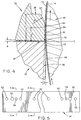
- the front face 42 of the upper lip 36 is configured to define (i) a wiping surface 60, (ii) a release surface 62 which curves away from the wiping surface 60 and away from the web 14, and (iii) a relief surface 64 extending from the slot 34 to the beginning of the wiping surface 60.
- the relief surface 64 is substantially straight and extends generally along a tangent to the transfer roll 16.
- the wiping and release surfaces comprise successive regions of a curved surface which begins at the end of the relief surface 64, and has a predetermined radius of curvature R1.
- the region of the curved surface which forms the wiping surface 60 begins at the end of the relief surface and is closely spaced from the web 14.
- the remainder of the curved surface, which forms the release surface 62, curves away from the wiping surface 60 and away from the web 14.
- the lower edge 70 of the relief surface 64 is adjacent the slot 34.
- the upper edge 72 of the lower lip 38 is also adjacent the slot 34.
- the lower edge 70 of the relief surface 64 is offset (or undercut) relative to the upper edge 72 of the lower lip 38.
- the relief surface 64 extends from the lower edge 70 toward the wiping surface 60 at a relief angle ⁇ of up to about 2°.
- the relief surface 64 cooperates with the moving web 14 to define a channel 66 which converges toward the wiping surface 60. That channel at least partially redirects (or guides) the hot melt varnish extruded through the slot 34 in the direction of movement of the web 14 and toward the wiping surface 60 during the coating process.
- the front face 40 of the lower lip 38 extends downward away from the upper edge 72.
- the upper edge 72 is not in contact with the web 14, but is located close enough to the web 14 to block flow of hot melt varnish past the lower die member 32.
- the remainder of the front face 40 is offset (or undercut) to extend away from the transfer roll 16, to provide an inlet through which the web 14 is guided into proximity with the coating die 12.
- hot melt varnish is extruded through the slot 34 and is formed by the coating die 12 into a smooth, streakless coating on the moving web 14.
- the coating die 12 is titled slightly downward at a small angle ⁇ (toward the direction of movement of the web 14).
- the lower lip 38 is located so that its upper edge 72 does not contact the web 14, but is close enough to the web 14 to block flow of hot melt varnish past the lower lip 38.
- the configuration of the upper lip 36 at least partially redirects (or guides) the hot melt varnish in the direction of the moving web 14 and toward the wiping surface 60.
- the wiping surface 60 lightly contacts the hot melt varnish, and gently wipes the varnish to a substantially smooth, streakless state.
- the release surface 62 gently curves away from the wiping surface 60 and away from the web 14, so that small particles in the varnish pass through the die, and can be released from the slot coating die 12.
- the particles pass through the die and become relatively harmless specks on the coating, but they do not accumulate in the slot coating die, and require interruption of the coating process to clean the slot coating die, or cause streaking of the varnish coating.
- a slot coating die constructed according to the principles of the present invention is particularly useful in a system for coating a web of printed label stock with a layer of hot melt varnish.
- An example of such a system would have the following configuration: Transfer Roll A Steel Roll with Silicon Cover Transfer Roll Diameter 6.0" Hot Melt Varnish Swift Adhesives' Type 2H195-01E Web Wrap (about Transfer Roll) 220° F.
- the foregoing example illustrates a slot coating die configuration which is particularly useful in connection with the preferred hot melt varnish, and a web being carried by a transfer roll having a 6.0" radius.
- Certain features of the slot die configuration such as (i) the radius of the rounded portion, (ii) the linear distance L1 from the slot to the end of the rounded portion, (iii) the linear distance L2 from the slot to the beginning of the wiping surface, (iv) the slot coating die tilt angle, (v) the relief angle ⁇ , and (vi) the extent of the upper die lip offset (or undercut) are related to each other, to allow for proper release of small particles from the slot coating die as the coating is being wiped to a substantially smooth finish.
- the specific relationship of those components may change with respect to each other, with changes in the size of the transfer roll, the type of hot melt varnish, etc.
- the transfer roll could be formed of chrome.
- the substrate, the printed label stock or other types of products could be formed of a material such as polyethylene.
- the slot coating die is located at about a nine o'clock position and in a generally horizontal orientation to the transfer roll (which is a common location and orientation), the die can be located at different positions about the periphery of the transfer roll.
- the relief surface 64 of the upper lip could be slightly curved, rather than straight.
- other hot melt materials such as an EVA (ethylene vinyl acetate) or a polyethylene type could be used. Still other modifications of the principles of the present invention, for applying hot melt coatings to various substrates, will be further apparent to those in the slot coating arts.
Landscapes
- Coating Apparatus (AREA)
- Application Of Or Painting With Fluid Materials (AREA)
Applications Claiming Priority (2)
| Application Number | Priority Date | Filing Date | Title |
|---|---|---|---|
| US14596093A | 1993-10-29 | 1993-10-29 | |
| US145960 | 1993-10-29 |
Publications (2)
| Publication Number | Publication Date |
|---|---|
| EP0650769A1 true EP0650769A1 (fr) | 1995-05-03 |
| EP0650769B1 EP0650769B1 (fr) | 2000-01-05 |
Family
ID=22515327
Family Applications (1)
| Application Number | Title | Priority Date | Filing Date |
|---|---|---|---|
| EP19940115809 Expired - Lifetime EP0650769B1 (fr) | 1993-10-29 | 1994-10-07 | Configuration de filière d'enduction en forme de fente |
Country Status (5)
| Country | Link |
|---|---|
| EP (1) | EP0650769B1 (fr) |
| JP (1) | JPH07185435A (fr) |
| AU (1) | AU674785B2 (fr) |
| CA (1) | CA2133266A1 (fr) |
| DE (1) | DE69422473T2 (fr) |
Families Citing this family (1)
| Publication number | Priority date | Publication date | Assignee | Title |
|---|---|---|---|---|
| WO2021048924A1 (fr) * | 2019-09-10 | 2021-03-18 | 株式会社 東芝 | Procédé de revêtement, tête de barre de revêtement et dispositif de revêtement |
Citations (2)
| Publication number | Priority date | Publication date | Assignee | Title |
|---|---|---|---|---|
| EP0025007A1 (fr) * | 1979-08-27 | 1981-03-11 | Acumeter Laboratories, Inc. | Applicateur d'adhésif et procédé pour relier des cigarettes avec des filtres et applications analogues |
| US4299186A (en) * | 1977-01-17 | 1981-11-10 | International Business Machines Corporation | Method and apparatus for applying a viscous fluid to a substrate |
Family Cites Families (7)
| Publication number | Priority date | Publication date | Assignee | Title |
|---|---|---|---|---|
| DE68922228T2 (de) * | 1988-01-20 | 1995-08-31 | Konishiroku Photo Ind | Beschichtungsvorrichtung. |
| JP2714850B2 (ja) * | 1989-04-07 | 1998-02-16 | コニカ株式会社 | 塗布装置および重層塗布方法 |
| JPH02277579A (ja) * | 1989-04-20 | 1990-11-14 | Fuji Photo Film Co Ltd | 塗布方法 |
| JP2601367B2 (ja) * | 1990-04-20 | 1997-04-16 | 富士写真フイルム株式会社 | 塗布方法 |
| JP2630522B2 (ja) * | 1991-10-18 | 1997-07-16 | 富士写真フイルム株式会社 | 塗布方法及び装置 |
| JP2684487B2 (ja) * | 1992-02-28 | 1997-12-03 | 富士写真フイルム株式会社 | 磁気記録媒体の塗布方法 |
| JPH06435A (ja) * | 1992-06-19 | 1994-01-11 | Sekisui Chem Co Ltd | 粘着剤の部分塗工装置及び部分塗工方法 |
-
1994
- 1994-09-29 CA CA 2133266 patent/CA2133266A1/fr not_active Abandoned
- 1994-10-07 DE DE1994622473 patent/DE69422473T2/de not_active Expired - Fee Related
- 1994-10-07 EP EP19940115809 patent/EP0650769B1/fr not_active Expired - Lifetime
- 1994-10-18 AU AU75897/94A patent/AU674785B2/en not_active Ceased
- 1994-10-28 JP JP6264315A patent/JPH07185435A/ja active Pending
Patent Citations (2)
| Publication number | Priority date | Publication date | Assignee | Title |
|---|---|---|---|---|
| US4299186A (en) * | 1977-01-17 | 1981-11-10 | International Business Machines Corporation | Method and apparatus for applying a viscous fluid to a substrate |
| EP0025007A1 (fr) * | 1979-08-27 | 1981-03-11 | Acumeter Laboratories, Inc. | Applicateur d'adhésif et procédé pour relier des cigarettes avec des filtres et applications analogues |
Also Published As
| Publication number | Publication date |
|---|---|
| AU674785B2 (en) | 1997-01-09 |
| AU7589794A (en) | 1995-05-18 |
| EP0650769B1 (fr) | 2000-01-05 |
| DE69422473D1 (de) | 2000-02-10 |
| JPH07185435A (ja) | 1995-07-25 |
| CA2133266A1 (fr) | 1995-04-30 |
| DE69422473T2 (de) | 2000-07-27 |
Similar Documents
| Publication | Publication Date | Title |
|---|---|---|
| EP1285700B1 (fr) | Appareil et méthode de revêtement | |
| JP4226331B2 (ja) | スパッタリング装置 | |
| US6837932B2 (en) | Pressure feed coating application system | |
| EP0757595B1 (fr) | Procede et appareil d'enduction par rouleau et filiere combines a levre de filiere perfectionnee | |
| WO2006113757A2 (fr) | Dispositif pour appliquer des fluides sur le contour d'un substrat | |
| US4310576A (en) | Adhesive-applying apparatus and method | |
| US4025671A (en) | Method for applying continuous longitudinal bands of liquid coating to a moving strip | |
| DE69805182D1 (de) | Verfahren und vorrichtung zum kontinuierlichen beschichten eines metallbandes mit einem film aus vernetzbarem fliessfähigem polymer | |
| EP0425562B1 (fr) | Procede et appareil de couchage au rideau | |
| EP0650769B1 (fr) | Configuration de filière d'enduction en forme de fente | |
| CA1330740C (fr) | Coucheuses de papier a grande vitesse | |
| EP0325206B1 (fr) | Dispositif pour appliquer un revêtement | |
| EP1646453B1 (fr) | Dispositif et procede de revetement de materiau | |
| CN1139887A (zh) | 正交流动的刮板涂料器 | |
| JP2001500784A (ja) | ストリップ上における縞状の塗装被覆の製造方法 | |
| JPH11505763A (ja) | 縞状にコーティングするためのインサート | |
| US5466291A (en) | Stand alone coating apparatus for printed material and method of operation thereof | |
| JPS63194766A (ja) | 塗布装置 | |
| JP2649952B2 (ja) | 溶融体又は液体の塗布方法とその装置 | |
| JP2523017Y2 (ja) | ロ−ラ−カ−テン塗装のカ−テン受け装置 | |
| JPH105664A (ja) | ダイコータ | |
| JPH06507120A (ja) | 移動する帯材にコーティング材料を塗布する装置 | |
| NL8403695A (nl) | Werkwijze voor het verwijderen van een beschermfolie van de kleefzijde van een zelfklevend elastisch profiel en het vervolgens aanbrengen van dit profiel op een lat of dergelijke. | |
| HK40017713A (en) | A system for applying a masking material to a substrate | |
| HK40017713B (en) | A system for applying a masking material to a substrate |
Legal Events
| Date | Code | Title | Description |
|---|---|---|---|
| PUAI | Public reference made under article 153(3) epc to a published international application that has entered the european phase |
Free format text: ORIGINAL CODE: 0009012 |
|
| AK | Designated contracting states |
Kind code of ref document: A1 Designated state(s): CH DE FR GB IT LI |
|
| 17P | Request for examination filed |
Effective date: 19951026 |
|
| 17Q | First examination report despatched |
Effective date: 19960621 |
|
| GRAG | Despatch of communication of intention to grant |
Free format text: ORIGINAL CODE: EPIDOS AGRA |
|
| GRAG | Despatch of communication of intention to grant |
Free format text: ORIGINAL CODE: EPIDOS AGRA |
|
| GRAH | Despatch of communication of intention to grant a patent |
Free format text: ORIGINAL CODE: EPIDOS IGRA |
|
| GRAH | Despatch of communication of intention to grant a patent |
Free format text: ORIGINAL CODE: EPIDOS IGRA |
|
| GRAA | (expected) grant |
Free format text: ORIGINAL CODE: 0009210 |
|
| AK | Designated contracting states |
Kind code of ref document: B1 Designated state(s): CH DE FR GB IT LI |
|
| REG | Reference to a national code |
Ref country code: CH Ref legal event code: EP |
|
| REF | Corresponds to: |
Ref document number: 69422473 Country of ref document: DE Date of ref document: 20000210 |
|
| ET | Fr: translation filed | ||
| REG | Reference to a national code |
Ref country code: CH Ref legal event code: NV Representative=s name: PATENTANWAELTE SCHAAD, BALASS, MENZL & PARTNER AG |
|
| ITF | It: translation for a ep patent filed | ||
| PLBE | No opposition filed within time limit |
Free format text: ORIGINAL CODE: 0009261 |
|
| STAA | Information on the status of an ep patent application or granted ep patent |
Free format text: STATUS: NO OPPOSITION FILED WITHIN TIME LIMIT |
|
| 26N | No opposition filed | ||
| REG | Reference to a national code |
Ref country code: GB Ref legal event code: IF02 |
|
| PGFP | Annual fee paid to national office [announced via postgrant information from national office to epo] |
Ref country code: FR Payment date: 20031103 Year of fee payment: 10 |
|
| PGFP | Annual fee paid to national office [announced via postgrant information from national office to epo] |
Ref country code: GB Payment date: 20041020 Year of fee payment: 11 Ref country code: CH Payment date: 20041020 Year of fee payment: 11 |
|
| PGFP | Annual fee paid to national office [announced via postgrant information from national office to epo] |
Ref country code: DE Payment date: 20041124 Year of fee payment: 11 |
|
| PG25 | Lapsed in a contracting state [announced via postgrant information from national office to epo] |
Ref country code: FR Free format text: LAPSE BECAUSE OF NON-PAYMENT OF DUE FEES Effective date: 20050630 |
|
| REG | Reference to a national code |
Ref country code: FR Ref legal event code: ST |
|
| PG25 | Lapsed in a contracting state [announced via postgrant information from national office to epo] |
Ref country code: IT Free format text: LAPSE BECAUSE OF NON-PAYMENT OF DUE FEES;WARNING: LAPSES OF ITALIAN PATENTS WITH EFFECTIVE DATE BEFORE 2007 MAY HAVE OCCURRED AT ANY TIME BEFORE 2007. THE CORRECT EFFECTIVE DATE MAY BE DIFFERENT FROM THE ONE RECORDED. Effective date: 20051007 Ref country code: GB Free format text: LAPSE BECAUSE OF NON-PAYMENT OF DUE FEES Effective date: 20051007 |
|
| PG25 | Lapsed in a contracting state [announced via postgrant information from national office to epo] |
Ref country code: LI Free format text: LAPSE BECAUSE OF NON-PAYMENT OF DUE FEES Effective date: 20051031 Ref country code: CH Free format text: LAPSE BECAUSE OF NON-PAYMENT OF DUE FEES Effective date: 20051031 |
|
| PG25 | Lapsed in a contracting state [announced via postgrant information from national office to epo] |
Ref country code: DE Free format text: LAPSE BECAUSE OF NON-PAYMENT OF DUE FEES Effective date: 20060503 |
|
| REG | Reference to a national code |
Ref country code: CH Ref legal event code: PL |
|
| GBPC | Gb: european patent ceased through non-payment of renewal fee |
Effective date: 20051007 |