EP0653557A2 - Système de commande de moteurs à combustion interne - Google Patents
Système de commande de moteurs à combustion interne Download PDFInfo
- Publication number
- EP0653557A2 EP0653557A2 EP95200248A EP95200248A EP0653557A2 EP 0653557 A2 EP0653557 A2 EP 0653557A2 EP 95200248 A EP95200248 A EP 95200248A EP 95200248 A EP95200248 A EP 95200248A EP 0653557 A2 EP0653557 A2 EP 0653557A2
- Authority
- EP
- European Patent Office
- Prior art keywords
- valve
- fuel
- fuel amount
- engine
- amount
- Prior art date
- Legal status (The legal status is an assumption and is not a legal conclusion. Google has not performed a legal analysis and makes no representation as to the accuracy of the status listed.)
- Granted
Links
Images


Classifications
-
- F—MECHANICAL ENGINEERING; LIGHTING; HEATING; WEAPONS; BLASTING
- F01—MACHINES OR ENGINES IN GENERAL; ENGINE PLANTS IN GENERAL; STEAM ENGINES
- F01L—CYCLICALLY OPERATING VALVES FOR MACHINES OR ENGINES
- F01L9/00—Valve-gear or valve arrangements actuated non-mechanically
- F01L9/10—Valve-gear or valve arrangements actuated non-mechanically by fluid means, e.g. hydraulic
- F01L9/11—Valve-gear or valve arrangements actuated non-mechanically by fluid means, e.g. hydraulic in which the action of a cam is being transmitted to a valve by a liquid column
- F01L9/12—Valve-gear or valve arrangements actuated non-mechanically by fluid means, e.g. hydraulic in which the action of a cam is being transmitted to a valve by a liquid column with a liquid chamber between a piston actuated by a cam and a piston acting on a valve stem
- F01L9/14—Valve-gear or valve arrangements actuated non-mechanically by fluid means, e.g. hydraulic in which the action of a cam is being transmitted to a valve by a liquid column with a liquid chamber between a piston actuated by a cam and a piston acting on a valve stem the volume of the chamber being variable, e.g. for varying the lift or the timing of a valve
-
- F—MECHANICAL ENGINEERING; LIGHTING; HEATING; WEAPONS; BLASTING
- F02—COMBUSTION ENGINES; HOT-GAS OR COMBUSTION-PRODUCT ENGINE PLANTS
- F02D—CONTROLLING COMBUSTION ENGINES
- F02D13/00—Controlling the engine output power by varying inlet or exhaust valve operating characteristics, e.g. timing
- F02D13/02—Controlling the engine output power by varying inlet or exhaust valve operating characteristics, e.g. timing during engine operation
- F02D13/0203—Variable control of intake and exhaust valves
- F02D13/0207—Variable control of intake and exhaust valves changing valve lift or valve lift and timing
-
- F—MECHANICAL ENGINEERING; LIGHTING; HEATING; WEAPONS; BLASTING
- F01—MACHINES OR ENGINES IN GENERAL; ENGINE PLANTS IN GENERAL; STEAM ENGINES
- F01L—CYCLICALLY OPERATING VALVES FOR MACHINES OR ENGINES
- F01L9/00—Valve-gear or valve arrangements actuated non-mechanically
- F01L9/10—Valve-gear or valve arrangements actuated non-mechanically by fluid means, e.g. hydraulic
- F01L9/11—Valve-gear or valve arrangements actuated non-mechanically by fluid means, e.g. hydraulic in which the action of a cam is being transmitted to a valve by a liquid column
-
- F—MECHANICAL ENGINEERING; LIGHTING; HEATING; WEAPONS; BLASTING
- F02—COMBUSTION ENGINES; HOT-GAS OR COMBUSTION-PRODUCT ENGINE PLANTS
- F02D—CONTROLLING COMBUSTION ENGINES
- F02D13/00—Controlling the engine output power by varying inlet or exhaust valve operating characteristics, e.g. timing
- F02D13/02—Controlling the engine output power by varying inlet or exhaust valve operating characteristics, e.g. timing during engine operation
- F02D13/0223—Variable control of the intake valves only
- F02D13/0226—Variable control of the intake valves only changing valve lift or valve lift and timing
- F02D13/023—Variable control of the intake valves only changing valve lift or valve lift and timing the change of valve timing is caused by the change in valve lift, i.e. both valve lift and timing are functionally related
-
- F—MECHANICAL ENGINEERING; LIGHTING; HEATING; WEAPONS; BLASTING
- F02—COMBUSTION ENGINES; HOT-GAS OR COMBUSTION-PRODUCT ENGINE PLANTS
- F02D—CONTROLLING COMBUSTION ENGINES
- F02D41/00—Electrical control of supply of combustible mixture or its constituents
- F02D41/02—Circuit arrangements for generating control signals
- F02D41/04—Introducing corrections for particular operating conditions
- F02D41/047—Taking into account fuel evaporation or wall wetting
-
- F—MECHANICAL ENGINEERING; LIGHTING; HEATING; WEAPONS; BLASTING
- F02—COMBUSTION ENGINES; HOT-GAS OR COMBUSTION-PRODUCT ENGINE PLANTS
- F02D—CONTROLLING COMBUSTION ENGINES
- F02D43/00—Conjoint electrical control of two or more functions, e.g. ignition, fuel-air mixture, recirculation, supercharging or exhaust-gas treatment
-
- F—MECHANICAL ENGINEERING; LIGHTING; HEATING; WEAPONS; BLASTING
- F02—COMBUSTION ENGINES; HOT-GAS OR COMBUSTION-PRODUCT ENGINE PLANTS
- F02M—SUPPLYING COMBUSTION ENGINES IN GENERAL WITH COMBUSTIBLE MIXTURES OR CONSTITUENTS THEREOF
- F02M25/00—Engine-pertinent apparatus for adding non-fuel substances or small quantities of secondary fuel to combustion-air, main fuel or fuel-air mixture
- F02M25/08—Engine-pertinent apparatus for adding non-fuel substances or small quantities of secondary fuel to combustion-air, main fuel or fuel-air mixture adding fuel vapours drawn from engine fuel reservoir
-
- F—MECHANICAL ENGINEERING; LIGHTING; HEATING; WEAPONS; BLASTING
- F01—MACHINES OR ENGINES IN GENERAL; ENGINE PLANTS IN GENERAL; STEAM ENGINES
- F01L—CYCLICALLY OPERATING VALVES FOR MACHINES OR ENGINES
- F01L1/00—Valve-gear or valve arrangements, e.g. lift-valve gear
- F01L1/34—Valve-gear or valve arrangements, e.g. lift-valve gear characterised by the provision of means for changing the timing of the valves without changing the duration of opening and without affecting the magnitude of the valve lift
- F01L1/344—Valve-gear or valve arrangements, e.g. lift-valve gear characterised by the provision of means for changing the timing of the valves without changing the duration of opening and without affecting the magnitude of the valve lift changing the angular relationship between crankshaft and camshaft, e.g. using helicoidal gear
- F01L1/3442—Valve-gear or valve arrangements, e.g. lift-valve gear characterised by the provision of means for changing the timing of the valves without changing the duration of opening and without affecting the magnitude of the valve lift changing the angular relationship between crankshaft and camshaft, e.g. using helicoidal gear using hydraulic chambers with variable volume to transmit the rotating force
- F01L2001/34423—Details relating to the hydraulic feeding circuit
- F01L2001/34446—Fluid accumulators for the feeding circuit
-
- F—MECHANICAL ENGINEERING; LIGHTING; HEATING; WEAPONS; BLASTING
- F01—MACHINES OR ENGINES IN GENERAL; ENGINE PLANTS IN GENERAL; STEAM ENGINES
- F01L—CYCLICALLY OPERATING VALVES FOR MACHINES OR ENGINES
- F01L2820/00—Details on specific features characterising valve gear arrangements
- F01L2820/02—Formulas
-
- F—MECHANICAL ENGINEERING; LIGHTING; HEATING; WEAPONS; BLASTING
- F02—COMBUSTION ENGINES; HOT-GAS OR COMBUSTION-PRODUCT ENGINE PLANTS
- F02B—INTERNAL-COMBUSTION PISTON ENGINES; COMBUSTION ENGINES IN GENERAL
- F02B2275/00—Other engines, components or details, not provided for in other groups of this subclass
- F02B2275/18—DOHC [Double overhead camshaft]
-
- F—MECHANICAL ENGINEERING; LIGHTING; HEATING; WEAPONS; BLASTING
- F02—COMBUSTION ENGINES; HOT-GAS OR COMBUSTION-PRODUCT ENGINE PLANTS
- F02D—CONTROLLING COMBUSTION ENGINES
- F02D41/00—Electrical control of supply of combustible mixture or its constituents
- F02D41/0002—Controlling intake air
- F02D2041/001—Controlling intake air for engines with variable valve actuation
-
- Y—GENERAL TAGGING OF NEW TECHNOLOGICAL DEVELOPMENTS; GENERAL TAGGING OF CROSS-SECTIONAL TECHNOLOGIES SPANNING OVER SEVERAL SECTIONS OF THE IPC; TECHNICAL SUBJECTS COVERED BY FORMER USPC CROSS-REFERENCE ART COLLECTIONS [XRACs] AND DIGESTS
- Y02—TECHNOLOGIES OR APPLICATIONS FOR MITIGATION OR ADAPTATION AGAINST CLIMATE CHANGE
- Y02T—CLIMATE CHANGE MITIGATION TECHNOLOGIES RELATED TO TRANSPORTATION
- Y02T10/00—Road transport of goods or passengers
- Y02T10/10—Internal combustion engine [ICE] based vehicles
- Y02T10/12—Improving ICE efficiencies
Definitions
- This invention relates to a control system for internal combustion engines, and more particularly to a control system which controls the supply of fuel injected into an intake pipe in a manner compensating for a fuel amount adhering to the inner surface of the intake pipe.
- GB-A-2228592 also relates to a similar system in which an adherent fuel amount is estimated based on the quantity of fuel injected and the fuel adhesion and evaporation rates, the adhesion rate being derived from the throttle opening and coolant temperature, and the evaporation rate being derived from coolant temperature, intake air quantity and engine speed.
- valve timing valve opening/closing timing and/or valve lift
- valve lift valve opening/closing timing and/or valve lift
- the present invention provides a control system for an internal combustion engine having at least one combustion chamber, an intake passage having an inner surface, at least one intake valve and at least one exhaust valve, the control system including supply fuel amount calculating means for calculating an amount of fuel to be supplied to the engine, based upon operating conditions of the engine, adherent fuel amount estimating means for estimating an amount of adherent fuel adhering to the inner surface of the intake passage, carried-off fuel amount estimating means for estimating an amount of carried-off fuel evaporated from fuel adhering to the inner surface of the intake passage and carried into the combustion chamber, supply fuel amount correcting means for correcting the supply fuel amount calculated by the supply fuel amount calculating means, based upon the adherent fuel amount estimated by the adherent fuel amount estimating means and the carried-off fuel amount estimated by the carried-off fuel amount estimating means, and fuel supply means for supplying the supply fuel amount corrected by the fuel amount correcting means into the intake passage, the system being characterised in that it further comprises: valve operating means for changing a valve operating characteristic of at least one
- the valve operating characteristic includes a low speed valve timing suitable for operation of the engine in a lower rotational speed region of the engine, and a high speed valve timing suitable for operation of the engine in a higher rotational speed region of the engine, the adherent fuel amount and the carried-off fuel amount being each corrected to different values between when the low speed valve timing is selected and when the high speed valve timing is selected.
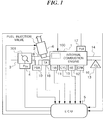
- FIG. 1 there is illustrated the whole arrangement of a fuel supply control system of an internal combustion engine.
- the intake pipe adherent fuel amount and the carried-off fuel amount are corrected in response to the valve timing of intake and exhaust valves.
- reference numeral 1 designates an internal combustion engine for automotive vehicles.
- the engine is a DOHC four-cylinder straight-type, for instance, having a pair of intake valves and a pair of exhaust valves provided for each cylinder, none of which is shown.
- an intake pipe 2 across which is arranged a throttle body 3 accommodating a throttle valve 301 therein.
- a throttle valve opening ( ⁇ TH ) sensor 4 is connected to the throttle valve 301 for generating an electric signal indicative of the sensed throttle valve opening and supplying same to an electronic control unit (hereinafter called "the ECU") 5.
- the ECU electronice control unit
- Fuel injection valves 6, only one of which is shown, are inserted into the interior of the intake pipe 2 at locations intermediate between the cylinder block of the engine 1 and the throttle valve 301 and slightly upstream of respective intake valves, not shown.
- the fuel injection valves 6 are connected to a fuel tank via a fuel pump (not shown), and electrically connected to the ECU 5 to have their valve opening periods controlled by signals therefrom.
- an intake pipe absolute pressure (PBA) sensor 10 is provided in communication with the interior of the intake pipe 2 via a conduit 9 at a location immediately downstream of the throttle valve 301 for supplying an electric signal indicative of the sensed absolute pressure within the intake pipe 2 to the ECU 5.
- PBA intake pipe absolute pressure
- An engine coolant temperature (TW) sensor 11 is mounted in the cylinder block of the engine 1, for supplying an electric signal indicative of the sensed engine coolant temperature TW to the ECU 5.
- An engine rotational speed (NE) sensor 12 is arranged in facing relation to a camshaft or a crankshaft of the engine 1, not shown. The engine rotational speed sensor 12 generates a pulse as a TDC signal pulse at each of predetermined crank angles whenever the crankshaft rotates through 180 degrees, the pulse being supplied to the ECU 5.
- An O2 sensor 13 as an exhaust gas ingredient concentration sensor is mounted in an exhaust pipe 14 connected to the cylinder block of the engine 1, for sensing the concentration of oxygen present in exhaust gases emitted from the engine 1 and supplying an electric signal indicative of the detected value of the oxygen concentration to the ECU 5.
- the ECU 5 comprises an input circuit having the functions of shaping the waveforms of input signals from various sensors, shifting the voltage levels of sensor output signals to a predetermined level, converting analog signals from analog-output sensors to digital signals, and so forth, a central processing unit (hereinafter called “the CPU") which executes programs for controlling the fuel injection valves 6, etc., memory means storing maps and tables, referred to hereinafter, and various operational programs which are executed in the CPU and for storing results of calculations therefrom, etc., and an output circuit which outputs control or driving signals to the fuel injection valves 6.
- the CPU central processing unit
- the CPU operates in response to the above-mentioned signals from the sensors to determine operating conditions in which the engine 1 is operating, such as an air-fuel ratio feedback control region in which the fuel supply is controlled in response to the detected oxygen concentration in the exhaust gases, and open-loop control regions, and calculates, based upon the determined operating conditions, the valve opening period of fuel injection period Tout over which the fuel injection valves 6 are to be opened, by the use of the program of Fig. 2 in synchronism with inputting of TDC signal pulses to the ECU 5.
- operating conditions in which the engine 1 is operating such as an air-fuel ratio feedback control region in which the fuel supply is controlled in response to the detected oxygen concentration in the exhaust gases, and open-loop control regions
- the CPU supplies via the output circuit the driving signals based upon the fuel injection period Tout determined as above to the fuel injection valves 6 to open same over the fuel injection period Tout.
- the fuel injection period Tout is proportional to the fuel injection amount, and therefore will be hereinafter referred to as the fuel injection amount.
- the engine 1 is provided with a valve timing changeover mechanism 100, which is capable of changing the valve timing of the intake valves and the exhaust valves between a high-speed valve timing (high speed V/T) suitable for engine operation in a higher engine rotational speed region and a low-speed valve timing (low speed V/T) suitable for engine operation in a lower engine rotational speed region.
- valve timing used in this specification includes the valve opening timing and/or valve closing timing, as well as the valve lift.
- An intake air temperature (TA) sensor 18 is mounted in the inner wall of the intake pipe 2 at a location downstream of the conduit 9 connected to the PBA sensor 10 for supplying an electric signal indicative of the sensed intake air temperature to the ECU 5.
- a cylinder-discriminating (CYL) sensor 15 and a crank angle (CRK) sensor 16 are arranged in facing relation to a camshaft or a crankshaft, neither of which is shown, of the engine 1 at respective predetermined locations thereof.
- the CYL sensor 15 generates a pulse signal (hereinafter referred to as "CYL signal pulse”) at predetermined crank angles of a particular cylinder whenever the crankshaft rotates two rotations or through 720 degrees and supplies the CYL signal pulse to the ECU 5.
- the CRK sensor 16 generates a pulse signal (hereinafter referred to as "CRK signal pulse") whenever the crankshaft rotates through a predetermined crank angle (e.g. 45°) and supplies the CRK signal pulse to the ECU 5.
- CRK signal pulse a pulse signal
- a predetermined crank angle e.g. 45°
- the output signal pulses from the CYL sensor 15 and CRK sensor 16 are used together with the output signal from the NE sensor 12, for control of the timing of execution of fuel injection timing control, ignition timing control, etc., as well as detection of the engine rotational speed NE.
- the valve timing changeover mechanism 100 has a solenoid valve, not shown, for changing the valve timing and is electrically connected to the ECU 5 to have its opening and closing operation controlled by a signal from the ECU 5.
- the solenoid valve changes operating oil pressure for the valve timing changeover mechanism 100 from a high level to a low level or vice versa, so that the valve timing is changed over from high speed V/T to low speed V/T or vice versa.
- the oil pressure in the changeover mechanism 100 is detected by an oil pressure (Poil) sensor 17, and the sensed signal is supplied to the ECU 5.
- the output circuit of the ECU 5 is adapted to supply driving signals to the fuel injection valves 6 and the solenoid valve of the valve timing changeover mechanism 100.
- Fig. 2 shows a program for calculating the valve opening period of the fuel injection valves 6, i.e. the fuel injection amount Tout. This program is executed upon generation of each TDC signal pulse and in synchronism therewith.
- a direct supply ratio A and a carry-off ratio B for the low speed V/T are calculated at a step S42.
- Values of the direct supply ratio A and the carry-off ratio B are read from an A map and a B map for the low speed V/T, which are set in accordance with the coolant temperature TW and the intake pipe absolute pressure PBA, in response to detected TW and PBA values.
- the direct supply ratio A and the carry-off ratio B for the low speed may be calculated by interpolation, if required.
- correction coefficients KA and KB for correcting the direct supply ratio A and the carry-off ratio B for the low speed V/T are calculated.
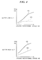
- Values of the correction coefficient KA and KB are read from a KA table and a KB table for the low speed V/T, shown in Fig. 4 (a), in response to the engine rotational speed NE.
- the correction coefficient KA for the direct supply ratio A and the correction coefficient KB for the carry-off ratio B are set such that they increase as the engine rotational speed NE increases.
- the reason why the correction coefficients KA and KB are thus increased as the engine rotational speed NE increases is that the direct supply ratio A and the carry-off ratio B apparently increase as the air flow speed in the intake pipe increases with an increase in the engine rotational speed NE.
- a direct supply ratio A, and a carry-off ratio B and correction coefficients KA, KB for the high speed V/T are calculated at steps S44 and S45, followed by the program proceeding to a step S46.
- values of the direct supply ratio A and the carry-off ratio B for the high speed V/T are read from an A map and a B map for the high speed V/T, and at the step S45, the correction coefficients KA, KB for the high speed V/T are calculated by the use of a KA table and a KB table for the high speed V/T, shown in Fig.4(b).
- two kinds of A maps and B maps as well as two kinds of correction coefficients KA and KB are provided, respectively, for the high speed V/T and low speed V/T.
- the reason for this is that the air flow speed in the vicinity of the intake valve and variation of pressure within the intake pipe 2 resulting from the variation, which are factors of fuel transportation parameters, differ depending upon the valve opening and/or closing timing and valve lift of the intake valve. Accordingly, the direct supply ratio A and the carry-off ratio B both vary depending on the valve timing of the intake valve. Therefore, the A map, B map, KA table and KB table have been set with the above-mentioned fact taken into account.
- a corrected direct supply ratio Ae and a corrected carry-off ratio Be are calculated by the use of the following equations (1) and (2) followed by calculating (1 - Ae) and (1 - Be) at a step S47, and then the program proceeds to a step S48:
- Ae A x KA (1)
- Be B x KB (2)
- the values Ae, (1 - Ae) and (1 - Be) are stored into the RAM within the ECU 5 for use in executing the program in Fig. 3 to calculate the intake pipe-adherent fuel amount TWP(N) described hereinafter, followed by the program proceeding to step S48.
- TiM represents a basic fuel amount to be applied when the engine is under normal operating conditions (other than the starting condition) and is calculated in response to the rotational speed NE and the intake pipe absolute pressure PBA.
- Ktotal(N) represents the product of all correction coefficients (e.g. a coolant temperature-dependent correction coefficient KTW and a leaning correction coefficient KLS) which are calculated based upon engine operating parameter signals from various sensors excluding an air-fuel ratio correction coefficient K02 which is calculated based on an output signal from the 02 sensor 13.
- correction coefficients e.g. a coolant temperature-dependent correction coefficient KTW and a leaning correction coefficient KLS
- TWP(N) represents an intake pipe-adherent fuel amount (estimated value), which is calculated by the program of Fig. 3.
- Be x TWP(N) corresponds to an amount of fuel, which is evaporated from fuel adhering to the inner surface of the intake pipe 2 and carried into the combustion chamber.
- a fuel amount corresponding to the fuel amount carried off the intake pipe inner surface need not be injected, and, therefore, is to be subtracted from the value Tcyl(N) in the equation (4).
- a fuel amount corresponding to TNET(N) X K02 + Be x TWP(N) is supplied to the combustion chamber by opening the fuel injection valve 6 over the time period Tout calculated by the equation (5).
- Fig. 3 shows the program for calculating the intake-pipe adherent fuel amount TWP(N), which is executed upon generation of each crank angle pulse which is generated whenever the crankshaft rotates through a predetermined angle (e.g. 30 degrees).
- a step S21 it is determined whether or not the present loop of execution of this program falls within a time period after the start of the calculation of the fuel injection amount Tout and before the fuel injection is completed (hereinafter referred to as the injection control period). If the answer is affirmative (YES), a first flag FCTWP(N) is set to a value of 0 at a step S32, followed by terminating the program. If the answer at the step S21 is negative (NO); i.e. if the present loop is not within the injection control period, it is determined at a step S22 whether or not the first flag FCTWP(N) is equal to 1.
- the first term on the right side corresponds to a fuel amount remaining on the inner surface of the intake pipe 2 without being carried into the combustion chamber, out of the fuel previously adhering to the inner surface of the intake pipe 2, and the second term on the right side corresponds to a fuel amount newly adhering to the inner surface of the intake pipe 2 out of newly injected fuel.
- TWP(N) (1 - Be) x TWP(N)(n -1) (7)
- the equation (7) is identical with the equation (6) except that the second term on the right side is omitted. The reason for the omission is that there is no fuel newly adhering to the intake pipe inner surface, due to fuel cut.
- the program proceeds to the next step S30. If the answer at the step S27 is negative (NO), i.e. if TWP(N) ⁇ TWPLG, the TWP(N) value is set to a value of 0 at a step S28, and then the second flag FTWPR(N) is set to a value of 1 at a step S29, followed by the program proceeding to the step S31.
- the intake pipe-adherent fuel amount TWP(N) can be accurately calculated. Moreover, an appropriate fuel amount can be supplied to the combustion chamber of each cylinder, which reflects the fuel amount adhering to the inner surface of the intake pipe 2 as well as the fuel amount carried off the adherent amount.
- the direct supply ratio A and the carry-off ratio B are calculated and corrected in response to valve timing selected, whereby it is possible to accurately estimate the intake pipe-adherent fuel amount, irrespective of valve timing selected and hence control the air-fuel ratio of a mixture supplied to the combustion chamber to a desired value.
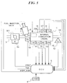
- Fig. 5 shows the whole arrangement of a fuel supply control system for an internal combustion engine, according to a second embodiment of the invention.
- the engine 1 is provided with an oil hydraulic driving valve unit 200 for each cylinder, in place of the valve timing changeover mechanism 100 employed in the arrangement of Fig. 1.
- the ECU 5 is connected to a solenoid of the oil hydraulic driving valve unit 200, and supplies control signals ( ⁇ OFF and ⁇ ON) thereto.
- a motor 3a is coupled to the throttle valve 301 for driving it in response to a control signal from the ECU 5 so as to control its valve opening.
- the throttle valve 301 is held at almost the maximum opening when the engine 1 is operating in normal operating conditions. With the throttle valve 301 thus held at almost the maximum opening, the valve opening period of the intake valve is changed by the oil hydraulic driving unit 200 to control an intake air amount supplied to the cylinder of the engine 1.
- an oil pressure sensor 17' which detects the pressure (Poil) of operating oil in the hydraulic driving valve unit 200, in place of the oil pressure sensor 17 in the first embodiment.
- an oil temperature sensor 19 which senses the oil temperature Toil of the operating oil
- a lift sensor 18 which senses the lift of the intake valve
- an accelerator pedal opening sensor 4' which senses a stepping amount ( ⁇ ACC) of an accelerator pedal, not shown, of a vehicle on which the engine is installed.
- Output signals from these sensors are supplied to the ECU 5.
- Fig. 6 shows the internal construction of the oil hydraulic driving valve unit 200 which is provided in each cylinder head 21 of the engine 1.
- the cylinder head 21 is formed therein with an intake valve port 23, one end of which opens into an upper space within a combustion chamber, not shown, of the engine 1 and the other end is in communication with an intake port 24.
- An intake valve 22 is slidably mounted in the cylinder head 21 arranged for vertical reciprocating motion as viewed in the figure to close and open the intake valve port 23.
- a valve spring 26 is tautly mounted between a collar 25 of the intake valve 22 and a spring seat 21a in the cylinder head 21 and urges the intake valve 22 upward as viewed in the figure or in a valve closing direction.
- a camshaft 28 having a cam 27 formed integrally thereon is rotatably mounted in the cylinder head 21 at a left side of the intake valve 22.
- the camshaft 28 is coupled to a crankshaft, not shown, via a timing belt, not shown.
- the oil hydraulic driving unit 200 is interposed between the intake valve 22 and the cam 27 formed on the camshaft 28.
- the oil hydraulic driving valve unit 200 is comprised of an oil hydraulic driving mechanism 30 disposed to downwardly urge the intake valve 22 against the force of the valve spring 26 to close or open same in response to the profile of the cam 27, and an oil pressure release mechanism 31 disposed to cancel the urging force of the oil hydraulic driving mechanism 30 while the intake valve 22 is being opened to thereby close the intake valve 22 irrespective of the cam profile.
- the oil hydraulic driving mechanism 30 is mainly comprised of a first cylinder body 33 secured to a block 32 mounted on or formed integrally with the cylinder head 21, a valve-side piston (valve driving piston) 34 slidably fitted in a cylinder bore 33a in the first cylinder body 33, with a lower end thereof resting against an upper end of the intake valve 22, an operating oil pressure chamber 38 defined by the first cylinder body 33 and the valve-side piston 34, a second cylinder body 36 secured to the block 32, a lifter 35 disposed in sliding contact with the cam 27, a cam-side piston 37 slidably fitted in a lower portion of the second cylinder body 36, with a lower end thereof resting against a bottom surface of the lifter 35, an oil hydraulic pressure creating chamber 39 defined by the second cylinder body 36 and the cam-side piston 37, and an oil passage 40 extending between the oil hydraulic pressure creating chamber 39 and the operating oil pressure chamber 38.
- the oil hydraulic driving mechanism 30 thus constructed operates according to the profile of the cam 27 to selectively open or close the intake
- the lift sensor 18 is arranged in the block 32 at a location opposite the collar 25 of the intake valve 22 to sense its lift.
- the lift sensor 18 is electrically connected to the ECU 5 to supply same with a signal indicative of the sensed lift.
- the oil pressure release mechanism 31 is mainly comprised of an oil passage 41 connecting between the oil passage 40 and an oil supply gallery 42, a spill valve 45 disposed to allow oil pressure to escape from the oil passage 41, a feed valve 43 and a check valve 44 both arranged in the oil passage 41, and an accumulator 46 disposed to maintain oil pressure within an accumulator circuit 41a formed by the valves 43, 44 and the spill valve 45 at a predetermined value.
- the oil supply gallery 42 is connected to an oil pump 47 to supply oil pressure created by the oil pump 47 to the oil hydraulic driving valve units 200 of the engine cylinders.
- the oil pump 47 pressurizes operating oil in an auxiliary oil pan 48 provided in the cylinder head 21 and supplies the pressurized oil to the oil supply gallery 42. It may be so arranged that the oil supply gallery 42 is supplied with operating oil from an oil pan provided at a bottom portion of a crankcase, not shown.
- the spill valve 45 is comprised of a control valve section 45A, and a solenoid driving section 45B for driving the control valve section 45A.
- the spill valve 45 when a solenoid 202 of the solenoid driving section 45B is deenergized, the spill valve 45 is open, whereas when the solenoid 202 is energized, the spill valve 45 is closed.
- the solenoid is electrically connected to the ECU 5 to be energized or deenergized by a control signal from the ECU 5.
- the accumulator 46 is arranged in the accumulator circuit 41a to maintain oil pressure within the accumulator circuit 41a at a predetermined value.
- the accumulator 46 is comprised of a cylinder bore 461 formed in the block 32, a cap 463 having an air hole 462 formed therein, a piston 464 slidably fitted in the cylinder bore 461, and a spring 465 tautly interposed between the cap 463 and the piston 464.
- the spill valve 45 When the solenoid 202 of the spill valve 45 is energized by the control signal from the ECU 5, the spill valve 45 is closed so that the oil pressure within the oil pressure creating chamber 39, the oil passage 40 and the operating oil pressure chamber 38 of the oil hydraulic driving mechanism 30 is maintained at a high level (at a predetermined pressure value or more), whereby the intake valve 22 is alternately opened and closed in response to the profile of the cam 27.
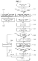
- the valve operating characteristic (the relationship between the crank angle and the valve lift) in this case is shown, by way of example, by the solid line in Fig. 7.
- the intake valve 22 begins to make a closing motion at a crank angle ⁇ ST after a slight time delay from the crank angle ⁇ OFF and becomes completely closed at a crank angle ⁇ IC (hereinafter referred to as "the intake valve closing timing").
- the intake valve 22 is controlled by the control signal from the ECU 5 such that it begins to make a closing motion when it is on the opening stroke, by rendering the oil hydraulic driving mechanism 30 inoperative. Therefore, the timing of valve closing start can be set to any desired timing, whereby it is possible to control the intake air amount supplied to the engine cylinders by the control signal from the ECU 5.
- a similar oil hydraulic driving unit is provided on the side of exhaust valves in this or second embodiment.
- an ordinary type valve operating mechanism in which the exhaust valve is closed at a constant timing according to a cam profile, or a variable valve timing mechanism in which the valve opening/closing timing can be set to a plurality of different timings, similarly to the valve timing changeover mechanism employed in this embodiment.
- the valve closing timing on the exhaust valve side will be referred to as “exhaust valve closing timing ⁇ EC", as corresponding to the intake valve timing ⁇ IC on the intake valve side.
- Fig. 8 shows a program for calculating the fuel injection amount Tout according to the second embodiment, which program corresponds to the one shown in Fig. 2.
- valve timing parameters i.e. intake valve closing timing ⁇ IC and exhaust valve closing timing ⁇ EC are read.
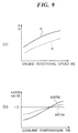
- the direct supply ratio A and the carry-off ratio B are calculated by the use of an A table and a B table shown in Fig. 9(a) in response to the detected engine rotational speed Ne.
- coolant temperature correction coefficients KATW and KBTW are calculated-in response to the detected engine coolant temperature by the use of a KATW table and a KBTW table set in accordance with the engine coolant temperature TW as shown in Fig. 9(b).
- the values of the A and B tables shown in Fig. 9(a) are set to values to be obtained when the engine output assumes 50% of its maximum value at each value of the engine rotational speed.
- reference values Abase and Bbase of the direct supply ratio and the carry-off ratio are also calculated by the use of the following equations 8 and 9:
- Abase A x KATW (8)
- Bbase B x KBTW (9)
- intake side correction coefficients KAIC and KBIC for the direct supply ratio and the carry-off ratio are calculated by the use of a KAIC table and a KBIC table set in accordance with the closing timing ⁇ IC of the intake valve, as shown in Fig. 10(a)
- exhaust-side correction coefficients KAEC and KBEC are calculated by the use of a KAEC table and a KBEC table set in accordance with the closing timing ⁇ EC of the exhaust valve, as shown in Fig.
- the steps S47 - S54 in Fig. 8 are identical with the steps S47 - S54 in Fig. 2, description of which is therefore omitted.
- the intake pipe-adherent fuel amount TWP(N) is calculated by the aforedescribed program in Fig. 3, also in this embodiment.
- the direct supply ratio A and the carry-off ratio B are corrected in response to the closing timing of the intake and exhaust valves. Therefore, it is possible to accurately estimate the intake pipe-adherent fuel amount and the carried-off fuel amount, irrespective of the closing timing of the intake and exhaust valves and hence accurately control the air-fuel ratio of a mixture supplied to the combustion chambers.
- the method of calculating the direct supply ratio A and the carry-off ratio B employed in the first and second embodiments described above is applicable to a valve control system in which part of the intake valves and/or part of the exhaust valves are rendered inoperative when the engine is operating in a low load condition.
- estimated values of the intake pipe-adherent fuel amount and the carried-off fuel amount are corrected in dependence on the valve operating characteristics of the intake valves and/or the exhaust valves, to thereby enable to accurately estimate the intake pipe-adherent fuel amount, irrespective of the valve operating characteristics and hence accurately control the air-fuel ratio of a mixture supplied to the combustion chambers.
Landscapes
- Engineering & Computer Science (AREA)
- Mechanical Engineering (AREA)
- General Engineering & Computer Science (AREA)
- Chemical & Material Sciences (AREA)
- Combustion & Propulsion (AREA)
- Electrical Control Of Air Or Fuel Supplied To Internal-Combustion Engine (AREA)
- Supplying Secondary Fuel Or The Like To Fuel, Air Or Fuel-Air Mixtures (AREA)
Applications Claiming Priority (10)
| Application Number | Priority Date | Filing Date | Title |
|---|---|---|---|
| JP28369491 | 1991-10-03 | ||
| JP283694/91 | 1991-10-03 | ||
| JP3283694A JP2623511B2 (ja) | 1991-10-03 | 1991-10-03 | 内燃機関の制御装置 |
| JP28712291 | 1991-10-07 | ||
| JP3287122A JP2623512B2 (ja) | 1991-10-07 | 1991-10-07 | 内燃機関の制御装置 |
| JP287122/91 | 1991-10-07 | ||
| JP305297/91 | 1991-10-24 | ||
| JP30529791 | 1991-10-24 | ||
| JP30529791A JP2623513B2 (ja) | 1991-10-24 | 1991-10-24 | 内燃機関の制御装置 |
| EP92309067A EP0536001B1 (fr) | 1991-10-03 | 1992-10-05 | Système de commande pour moteurs à combustion interne |
Related Parent Applications (2)
| Application Number | Title | Priority Date | Filing Date |
|---|---|---|---|
| EP92309067A Division EP0536001B1 (fr) | 1991-10-03 | 1992-10-05 | Système de commande pour moteurs à combustion interne |
| EP92309067.4 Division | 1992-10-05 |
Publications (3)
| Publication Number | Publication Date |
|---|---|
| EP0653557A2 true EP0653557A2 (fr) | 1995-05-17 |
| EP0653557A3 EP0653557A3 (fr) | 1997-12-17 |
| EP0653557B1 EP0653557B1 (fr) | 2000-03-22 |
Family
ID=27337031
Family Applications (3)
| Application Number | Title | Priority Date | Filing Date |
|---|---|---|---|
| EP96100342A Expired - Lifetime EP0711909B1 (fr) | 1991-10-03 | 1992-10-05 | Système de commande pour moteurs à combustion interne |
| EP95200248A Expired - Lifetime EP0653557B1 (fr) | 1991-10-03 | 1992-10-05 | Système de commande de moteurs à combustion interne |
| EP92309067A Expired - Lifetime EP0536001B1 (fr) | 1991-10-03 | 1992-10-05 | Système de commande pour moteurs à combustion interne |
Family Applications Before (1)
| Application Number | Title | Priority Date | Filing Date |
|---|---|---|---|
| EP96100342A Expired - Lifetime EP0711909B1 (fr) | 1991-10-03 | 1992-10-05 | Système de commande pour moteurs à combustion interne |
Family Applications After (1)
| Application Number | Title | Priority Date | Filing Date |
|---|---|---|---|
| EP92309067A Expired - Lifetime EP0536001B1 (fr) | 1991-10-03 | 1992-10-05 | Système de commande pour moteurs à combustion interne |
Country Status (4)
| Country | Link |
|---|---|
| US (1) | US5215061A (fr) |
| EP (3) | EP0711909B1 (fr) |
| CA (1) | CA2077068C (fr) |
| DE (3) | DE69218538T2 (fr) |
Cited By (2)
| Publication number | Priority date | Publication date | Assignee | Title |
|---|---|---|---|---|
| WO1997006355A1 (fr) * | 1995-08-08 | 1997-02-20 | Diesel Engine Retarders, Inc. | Moteurs a combustion interne a commande combinee de came et de soupape electro-hydaulique |
| EP1291511A3 (fr) * | 2001-09-07 | 2006-04-05 | Honda Giken Kogyo Kabushiki Kaisha | Appareil de commande d'injection de carburant |
Families Citing this family (45)
| Publication number | Priority date | Publication date | Assignee | Title |
|---|---|---|---|---|
| US5390644A (en) * | 1991-12-27 | 1995-02-21 | Nippondenso Co., Ltd. | Method for producing fuel/air mixture for combustion engine |
| JPH05312072A (ja) * | 1992-05-07 | 1993-11-22 | Honda Motor Co Ltd | 内燃エンジンの空燃比制御装置 |
| US5363832A (en) * | 1992-05-14 | 1994-11-15 | Nippondenso Co., Ltd. | Fuel vapor purging control system with air/fuel ratio compensating system for internal combustion engine |
| JP2829891B2 (ja) * | 1992-06-18 | 1998-12-02 | 株式会社ユニシアジェックス | 内燃機関の燃料噴射タイミング制御装置 |
| US5426938A (en) * | 1992-09-18 | 1995-06-27 | Honda Giken Kogyo Kabushiki Kaisha | Control system for internal combustion engines |
| JPH06146948A (ja) * | 1992-10-16 | 1994-05-27 | Unisia Jecs Corp | 蒸発燃料処理装置を備える内燃機関の空燃比制御装置 |
| JPH06323181A (ja) * | 1993-05-14 | 1994-11-22 | Hitachi Ltd | 内燃機関の燃料制御方法及びその装置 |
| US5476081A (en) * | 1993-06-14 | 1995-12-19 | Toyota Jidosha Kabushiki Kaisha | Apparatus for controlling air-fuel ratio of air-fuel mixture to an engine having an evaporated fuel purge system |
| US5404856A (en) * | 1993-06-28 | 1995-04-11 | Ford Motor Company | Fuel injector control utilizing fuel film flow parameters |
| US5408972A (en) * | 1993-06-28 | 1995-04-25 | Ford Motor Company | Fuel injector control incorporating fuel vaporization parameters |
| JPH0797943A (ja) * | 1993-09-29 | 1995-04-11 | Honda Motor Co Ltd | 内燃エンジンの制御装置 |
| JPH0730353U (ja) * | 1993-11-09 | 1995-06-06 | 本田技研工業株式会社 | 内燃エンジンの蒸発燃料制御装置 |
| JP2896298B2 (ja) * | 1993-11-26 | 1999-05-31 | 株式会社日立製作所 | キャニスタパージ制御装置及び制御方法 |
| JP3045921B2 (ja) * | 1994-03-09 | 2000-05-29 | 本田技研工業株式会社 | 内燃エンジンの燃料噴射制御装置 |
| DE69530721T2 (de) * | 1994-04-14 | 2004-03-18 | Honda Giken Kogyo K.K. | System zur Schätzung der Abgasrückführungsrate für einen Verbrennungsmotor |
| US5560347A (en) * | 1994-05-02 | 1996-10-01 | General Motors Corporation | Conductive foam vapor sensing |
| JP3325392B2 (ja) * | 1994-07-06 | 2002-09-17 | 本田技研工業株式会社 | 内燃エンジンの燃料噴射制御装置 |
| JP3354304B2 (ja) * | 1994-07-29 | 2002-12-09 | 本田技研工業株式会社 | 内燃機関の燃料噴射制御装置 |
| JPH0893529A (ja) * | 1994-09-21 | 1996-04-09 | Honda Motor Co Ltd | 内燃機関の燃料噴射制御装置 |
| JPH08121211A (ja) * | 1994-10-27 | 1996-05-14 | Honda Motor Co Ltd | 内燃エンジンの燃料制御装置 |
| US5657736A (en) * | 1994-12-30 | 1997-08-19 | Honda Giken Kogyo Kabushiki Kaisha | Fuel metering control system for internal combustion engine |
| US5758308A (en) * | 1994-12-30 | 1998-05-26 | Honda Giken Kogyo Kabushiki Kaisha | Fuel metering control system for internal combustion engine |
| US7222614B2 (en) | 1996-07-17 | 2007-05-29 | Bryant Clyde C | Internal combustion engine and working cycle |
| US8215292B2 (en) | 1996-07-17 | 2012-07-10 | Bryant Clyde C | Internal combustion engine and working cycle |
| US7281527B1 (en) | 1996-07-17 | 2007-10-16 | Bryant Clyde C | Internal combustion engine and working cycle |
| AUPO355896A0 (en) * | 1996-11-11 | 1996-12-05 | Underwater Mobile Observatories International Pty Ltd | An underwater mobile observatory system |
| JPH10318015A (ja) * | 1997-05-20 | 1998-12-02 | Denso Corp | 内燃機関の空燃比制御装置 |
| JPH1136918A (ja) * | 1997-07-14 | 1999-02-09 | Toyota Motor Corp | 内燃機関の蒸発燃料処理装置 |
| JPH11159356A (ja) * | 1997-09-24 | 1999-06-15 | Denso Corp | 内燃機関用バルブタイミング制御装置 |
| JP3562351B2 (ja) * | 1998-11-24 | 2004-09-08 | トヨタ自動車株式会社 | 内燃機関の燃料ポンプ制御装置 |
| DE10060350A1 (de) | 2000-12-04 | 2002-06-06 | Mahle Filtersysteme Gmbh | Be- und Entlüftungseinrichtung des Kraftstoff-Tankes eines Verbrennungsmotors |
| US7201121B2 (en) | 2002-02-04 | 2007-04-10 | Caterpillar Inc | Combustion engine including fluidically-driven engine valve actuator |
| US7178492B2 (en) | 2002-05-14 | 2007-02-20 | Caterpillar Inc | Air and fuel supply system for combustion engine |
| US6688280B2 (en) | 2002-05-14 | 2004-02-10 | Caterpillar Inc | Air and fuel supply system for combustion engine |
| US7191743B2 (en) | 2002-05-14 | 2007-03-20 | Caterpillar Inc | Air and fuel supply system for a combustion engine |
| US7252054B2 (en) | 2002-05-14 | 2007-08-07 | Caterpillar Inc | Combustion engine including cam phase-shifting |
| JP4337374B2 (ja) * | 2003-02-07 | 2009-09-30 | 三菱電機株式会社 | 蒸散燃料ガスリーク検出装置 |
| DE602004020536D1 (de) * | 2003-03-11 | 2009-05-28 | Nissan Motor | Kraftstoffeinspritzsteuerungsvorrichtung einer Brennkraftmaschine |
| US7124731B2 (en) * | 2003-09-19 | 2006-10-24 | Honda Motor Co., Ltd. | Internal combustion engine with oil temperature sensor |
| JP4322799B2 (ja) * | 2004-03-25 | 2009-09-02 | 株式会社日本自動車部品総合研究所 | 内燃機関の蒸発燃料処理装置 |
| JP4345660B2 (ja) * | 2004-12-17 | 2009-10-14 | トヨタ自動車株式会社 | 内燃機関制御装置 |
| US7607410B2 (en) * | 2006-06-12 | 2009-10-27 | Ford Global Technologies, Llc | System and method of controlling fuel delivery during positive valve overlap operation of an engine start |
| DE602007000440D1 (de) * | 2007-02-08 | 2009-02-12 | Delphi Tech Inc | Kraftstoffdampf-Tankentlüftungssystem für einen Fahrzeugkraftstofftank |
| JP5077686B2 (ja) * | 2008-03-27 | 2012-11-21 | 本田技研工業株式会社 | 内燃機関の冷却装置 |
| AU2013315003B2 (en) * | 2012-09-17 | 2016-11-03 | Steelcase Inc. | Floor-to-ceiling partition wall assembly |
Family Cites Families (12)
| Publication number | Priority date | Publication date | Assignee | Title |
|---|---|---|---|---|
| JPS5344718A (en) * | 1976-10-04 | 1978-04-21 | Toyota Motor Corp | Fuel evaporation gas processing apparatus |
| JPS6046705B2 (ja) * | 1978-07-06 | 1985-10-17 | 凸版印刷株式会社 | 切抜きマスク版の作成方法及び装置 |
| US4357923A (en) * | 1979-09-27 | 1982-11-09 | Ford Motor Company | Fuel metering system for an internal combustion engine |
| JPS588239A (ja) * | 1981-07-06 | 1983-01-18 | Toyota Motor Corp | 燃料噴射式エンジンの燃料噴射量制御方法 |
| JPS588238A (ja) * | 1981-07-06 | 1983-01-18 | Toyota Motor Corp | 燃料噴射式エンジンの燃料噴射量制御方法 |
| JP2550014B2 (ja) * | 1984-11-26 | 1996-10-30 | 株式会社日立製作所 | エンジンの燃料噴射制御方法 |
| DE3636810A1 (de) * | 1985-10-29 | 1987-04-30 | Nissan Motor | Kraftstoffeinspritzregelsystem fuer eine brennkraftmaschine |
| JPH0695350B2 (ja) * | 1988-08-12 | 1994-11-24 | 三菱電機株式会社 | Icメモリカード用バッテリ回路 |
| JPH02227532A (ja) * | 1989-02-28 | 1990-09-10 | Fuji Heavy Ind Ltd | 燃料噴射制御装置 |
| US5086744A (en) * | 1990-01-12 | 1992-02-11 | Mazda Motor Corporation | Fuel control system for internal combustion engine |
| JPH0460132A (ja) * | 1990-06-29 | 1992-02-26 | Mazda Motor Corp | エンジンの燃料制御装置 |
| US5048492A (en) * | 1990-12-05 | 1991-09-17 | Ford Motor Company | Air/fuel ratio control system and method for fuel vapor purging |
-
1992
- 1992-08-27 CA CA002077068A patent/CA2077068C/fr not_active Expired - Fee Related
- 1992-09-16 US US07/945,489 patent/US5215061A/en not_active Expired - Lifetime
- 1992-10-05 EP EP96100342A patent/EP0711909B1/fr not_active Expired - Lifetime
- 1992-10-05 EP EP95200248A patent/EP0653557B1/fr not_active Expired - Lifetime
- 1992-10-05 DE DE69218538T patent/DE69218538T2/de not_active Expired - Fee Related
- 1992-10-05 DE DE69230647T patent/DE69230647T2/de not_active Expired - Fee Related
- 1992-10-05 EP EP92309067A patent/EP0536001B1/fr not_active Expired - Lifetime
- 1992-10-05 DE DE69230833T patent/DE69230833T2/de not_active Expired - Fee Related
Cited By (4)
| Publication number | Priority date | Publication date | Assignee | Title |
|---|---|---|---|---|
| WO1997006355A1 (fr) * | 1995-08-08 | 1997-02-20 | Diesel Engine Retarders, Inc. | Moteurs a combustion interne a commande combinee de came et de soupape electro-hydaulique |
| US5680841A (en) * | 1995-08-08 | 1997-10-28 | Diesel Engine Retarders, Inc. | Internal combustion engines with combined cam and electro-hydraulic engine valve control |
| US5839453A (en) * | 1995-08-08 | 1998-11-24 | Diesel Engine Retarders, Inc. | Internal combustion engines with combined cam and electro-hydraulic engine valve control |
| EP1291511A3 (fr) * | 2001-09-07 | 2006-04-05 | Honda Giken Kogyo Kabushiki Kaisha | Appareil de commande d'injection de carburant |
Also Published As
| Publication number | Publication date |
|---|---|
| EP0653557B1 (fr) | 2000-03-22 |
| EP0711909B1 (fr) | 2000-02-02 |
| DE69230833D1 (de) | 2000-04-27 |
| US5215061A (en) | 1993-06-01 |
| EP0536001B1 (fr) | 1997-03-26 |
| DE69230647T2 (de) | 2000-10-26 |
| EP0711909A3 (fr) | 1997-12-17 |
| DE69230647D1 (de) | 2000-03-09 |
| DE69218538D1 (de) | 1997-04-30 |
| EP0711909A2 (fr) | 1996-05-15 |
| CA2077068A1 (fr) | 1993-04-04 |
| EP0653557A3 (fr) | 1997-12-17 |
| DE69218538T2 (de) | 1997-07-03 |
| CA2077068C (fr) | 1997-03-25 |
| EP0536001A1 (fr) | 1993-04-07 |
| DE69230833T2 (de) | 2000-11-30 |
Similar Documents
| Publication | Publication Date | Title |
|---|---|---|
| EP0653557B1 (fr) | Système de commande de moteurs à combustion interne | |
| EP0446065B1 (fr) | Méthode de commande d'un moteur à combustion interne | |
| EP0691463B1 (fr) | Système de commande d'injection de carburant pour moteurs à combustion interne | |
| US5482020A (en) | Control system for internal combustion engines | |
| US5419301A (en) | Adaptive control of camless valvetrain | |
| US4960083A (en) | Failsafe method in connection with valve timing-changeover control for internal combustion engines | |
| US5629853A (en) | Fuel injection control system for internal combustion engines | |
| EP0525597B1 (fr) | Système de commande du rapport air/carburant pour un moteur du type à distribution variable | |
| EP0551207B1 (fr) | Système de commande de moteurs à combustion interne | |
| US5000280A (en) | Driving wheel slip control system for vehicles | |
| US5690074A (en) | Fuel injection control system for internal combustion engines | |
| US5638792A (en) | Control system for internal combustion engines | |
| EP0582719B1 (fr) | Dispositif de commande pour moteur a mecanisme de soupapes d'admission et d'echappement variables et son procede de commande | |
| US5494019A (en) | Control system for internal combustion engines | |
| US5551408A (en) | Exhaust gas recirculation control system for internal combustion engines | |
| US5572978A (en) | Fuel injection control system for internal combustion engines | |
| US5163403A (en) | Ignition timing control system for internal combustion engines | |
| EP0569251B1 (fr) | Système de commande de rapport air/carburant pour un moteur à combustion interne | |
| JP2623512B2 (ja) | 内燃機関の制御装置 | |
| JPH0754563Y2 (ja) | 内燃エンジンの動弁装置 |
Legal Events
| Date | Code | Title | Description |
|---|---|---|---|
| PUAI | Public reference made under article 153(3) epc to a published international application that has entered the european phase |
Free format text: ORIGINAL CODE: 0009012 |
|
| AC | Divisional application: reference to earlier application |
Ref document number: 536001 Country of ref document: EP |
|
| AK | Designated contracting states |
Kind code of ref document: A2 Designated state(s): DE FR GB |
|
| PUAL | Search report despatched |
Free format text: ORIGINAL CODE: 0009013 |
|
| AK | Designated contracting states |
Kind code of ref document: A3 Designated state(s): DE FR GB |
|
| 17P | Request for examination filed |
Effective date: 19980404 |
|
| GRAG | Despatch of communication of intention to grant |
Free format text: ORIGINAL CODE: EPIDOS AGRA |
|
| 17Q | First examination report despatched |
Effective date: 19990511 |
|
| GRAG | Despatch of communication of intention to grant |
Free format text: ORIGINAL CODE: EPIDOS AGRA |
|
| GRAH | Despatch of communication of intention to grant a patent |
Free format text: ORIGINAL CODE: EPIDOS IGRA |
|
| GRAH | Despatch of communication of intention to grant a patent |
Free format text: ORIGINAL CODE: EPIDOS IGRA |
|
| GRAA | (expected) grant |
Free format text: ORIGINAL CODE: 0009210 |
|
| AC | Divisional application: reference to earlier application |
Ref document number: 536001 Country of ref document: EP |
|
| AK | Designated contracting states |
Kind code of ref document: B1 Designated state(s): DE FR GB |
|
| PG25 | Lapsed in a contracting state [announced via postgrant information from national office to epo] |
Ref country code: FR Free format text: THE PATENT HAS BEEN ANNULLED BY A DECISION OF A NATIONAL AUTHORITY Effective date: 20000322 |
|
| REF | Corresponds to: |
Ref document number: 69230833 Country of ref document: DE Date of ref document: 20000427 |
|
| ET | Fr: translation filed | ||
| PLBE | No opposition filed within time limit |
Free format text: ORIGINAL CODE: 0009261 |
|
| STAA | Information on the status of an ep patent application or granted ep patent |
Free format text: STATUS: NO OPPOSITION FILED WITHIN TIME LIMIT |
|
| 26N | No opposition filed | ||
| REG | Reference to a national code |
Ref country code: GB Ref legal event code: IF02 |
|
| REG | Reference to a national code |
Ref country code: FR Ref legal event code: ST |
|
| PGFP | Annual fee paid to national office [announced via postgrant information from national office to epo] |
Ref country code: GB Payment date: 20061004 Year of fee payment: 15 |
|
| GBPC | Gb: european patent ceased through non-payment of renewal fee |
Effective date: 20071005 |
|
| PG25 | Lapsed in a contracting state [announced via postgrant information from national office to epo] |
Ref country code: GB Free format text: LAPSE BECAUSE OF NON-PAYMENT OF DUE FEES Effective date: 20071005 |
|
| PGFP | Annual fee paid to national office [announced via postgrant information from national office to epo] |
Ref country code: DE Payment date: 20081014 Year of fee payment: 17 |
|
| PG25 | Lapsed in a contracting state [announced via postgrant information from national office to epo] |
Ref country code: DE Free format text: LAPSE BECAUSE OF NON-PAYMENT OF DUE FEES Effective date: 20100501 |