EP0656579A2 - Stromverwaltung für Rechnersystem - Google Patents
Stromverwaltung für Rechnersystem Download PDFInfo
- Publication number
- EP0656579A2 EP0656579A2 EP94308628A EP94308628A EP0656579A2 EP 0656579 A2 EP0656579 A2 EP 0656579A2 EP 94308628 A EP94308628 A EP 94308628A EP 94308628 A EP94308628 A EP 94308628A EP 0656579 A2 EP0656579 A2 EP 0656579A2
- Authority
- EP
- European Patent Office
- Prior art keywords
- oscillator
- clock
- signal
- control unit
- power
- Prior art date
- Legal status (The legal status is an assumption and is not a legal conclusion. Google has not performed a legal analysis and makes no representation as to the accuracy of the status listed.)
- Granted
Links
Images
Classifications
-
- G—PHYSICS
- G06—COMPUTING OR CALCULATING; COUNTING
- G06F—ELECTRIC DIGITAL DATA PROCESSING
- G06F1/00—Details not covered by groups G06F3/00 - G06F13/00 and G06F21/00
- G06F1/04—Generating or distributing clock signals or signals derived directly therefrom
Definitions
- This invention relates to computer systems and more particularly to power management techniques employed within computer systems.
- One specific power reduction technique involves the capability of stopping clock signals that drive inactive circuit portions such as the microprocessor, a system memory, and a disk controller.
- a system employing such a technique typically includes a power management unit that detects or predicts when the microprocessor, the system memory, and the disk controller will be inactive, and accordingly stops the clock signals at appropriate times. By turning off "unused" clock signals that drive the inactive circuit portions, overall power consumption of the system is decreased.
- a similar technique involves removing the power supplied to the microprocessor, the system memory, and the disk controller when they are inactive.
- a computer system employing a system oscillator gating technique in accordance with the present invention.
- digital hardware is utilized to control the removal and the reapplication of power to the system oscillator.
- an output signal from a power management unit is provided to turn off the external system oscillator when the computer system is in a power-conserving suspend state and to turn on the external system oscillator on when the computer system resumes to a ready state.
- Counters are provided to control the latency of the output signal when the power management unit enters and exits the suspend state.
- This latency provides time for the microprocessor clock and/or other clock signals associated with the system oscillator to shut off prior to the oscillator shutdown and provides time for the oscillator to stabilize prior to the restarting of the clock signal. As a result, power consumption of the computer system may be reduced while proper clock generation for the computer system is maintained.
- the present invention contemplates a computer system comprising an oscillator for generating a reference timing signal, a clock generator coupled to the oscillator and capable of generating a clock signal, and a system monitor for monitoring a circuit portion of the computer system and capable of generating a suspend state signal indicative of whether said circuit portion is inactive.
- a clock control unit is also provided that is coupled to the clock generator and to the system monitor, wherein the clock control unit is capable of stopping the clock signal in response to an assertion of the suspend state signal and is capable of restarting the clock signal in response to a deassertion of the suspend state signal.
- the computer system finally includes an oscillator power control unit coupled to the oscillator and to the system monitor, wherein the oscillator power control unit is capable of removing power supplied to the oscillator in response to an assertion of the suspend state signal.
- the present invention further contemplates a power management unit connectable to a computer system including an oscillator for providing a timing reference signal.
- the power management unit comprises a system monitor for monitoring a circuit portion of the computer system and capable of generating a suspend state signal indicative of whether the circuit portion is inactive, a clock control unit coupled to the system monitor, wherein the clock control unit is capable of generating a clock suspend signal in response to an assertion of the suspend state signal, and an oscillator power control unit coupled to the system monitor.
- the oscillator power control unit is capable of generating an oscillator gating signal for controlling the application of power to the oscillator in response to the suspend state signal.
- the present invention finally contemplates a power management method for removing and applying power to a system oscillator within a computer system comprising the steps of monitoring a circuit portion of the computer system, entering a suspend state if the circuit portion is inactive, stopping a clock signal in response to the step of entering the suspend state, and removing power from the system oscillator in response to the step of entering the suspend state.
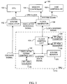
- Figure 1 is a block diagram of a computer system including a power management unit that implements a system oscillator gating technique in accordance with the present invention.
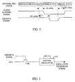
- Figure 2 is a timing diagram that illustrates the internal power management states of the power management unit and corresponding output control signals.
- Figure 3 is a schematic diagram that illustrates a gating circuit for removing and reapplying power to the system oscillator.
- FIG. 1 is a block diagram of a computer system 100 that implements a system oscillator gating technique according to the present invention.
- the computer system 100 includes a microprocessor (CPU) 102, a system memory controller 104, and a disk controller 106 each coupled to a clock generator 108.
- the computer system 100 further includes a power management unit (PMU) 110 and a system oscillator 112 coupled to clock generator 108.
- PMU power management unit
- System oscillator 112 is an oscillator circuit which, in the preferred embodiment, includes a crystal element and which generates an oscillator reference signal having a predetermined frequency.
- the oscillator reference signal is provided to clock generator 108.
- clock generator 108 uses the oscillator reference signal, clock generator 108 generates a CPU clock signal that is provided to microprocessor 102 and a system clock signal that is provided to system memory controller 104 and to disk controller 106, among other things.
- the CPU clock signal may have a different frequency from the system clock signal.
- the CPU clock signal has a maximum frequency of 80 MHz and the system clock signal has a maximum frequency of 40 MHz.
- Power management unit 110 includes a system monitor 120 coupled to an oscillator power control unit 122 and to a clock control unit 124.
- a counter 126 is coupled to oscillator power control unit 122 and a pair of counters 128 and 130 are coupled to clock control unit 124.
- system oscillator 112 During operation, system oscillator 112 generates an oscillator reference signal having a predetermined frequency of, for example, 80 MHz.
- Clock generator 108 uses this oscillator reference signal to generate the CPU clock signal and the system clock signal.
- system monitor 120 monitors various subsystems of the computer system 100 such as the microprocessor 102, system memory controller 104, and disk controller 106, among other things.
- system monitor 120 detects activity of the microprocessor and other system peripherals by detecting signal activity on the CPU local bus and/or a peripheral bus.
- a variety of specific implementations of system monitor 120 could be employed within power management unit 110, and exemplary system monitors are described in numerous publications of the known prior art. For example, an exemplary system monitor that detects inactive circuit portions of a computer system is described within U.S. Patent No. 5,167,024 issued November 24, 1992 to Smith et al. This patent is incorporated herein by reference in its entirety.
- system monitor 120 When system monitor 120 determines that the microprocessor 102, the system memory controller 104, and the disk controller 106 are inactive, system monitor 120 enters a suspend state during which a control signal identified herein as the suspend state signal is asserted.
- the suspend state signal is provided to oscillator power control unit 122 and clock control unit 124.
- the oscillator power control unit 122 responsively asserts a control signal identified as the OSCGATE signal which causes the power to be removed from the system oscillator
- clock control unit 124 asserts a control signal identified as the clock suspend signal that causes the clock generator 108 to stop the CPU clock signal and the system clock signal.
- Figure 2 is a timing diagram that illustrates the timing relationship between the internal states of system monitor 120 and the clock suspend and OSCGATE signals.
- the clock control unit 124 when system monitor 120 enters the suspend state and asserts the suspend state signal, the clock control unit 124 causes counter 128 to begin counting a period of 30 microseconds. When the 30 microsecond period elapses, clock control unit 124 asserts the clock suspend signal which causes clock generator 108 to stop the CPU clock signal and the system clock signal.
- Oscillator power control unit 122 similarly causes the counter 126 to begin counting for a 150 microsecond period in response to the entrance of the suspend state by system monitor 120. After 150 microseconds have elapsed, oscillator power control unit 122 asserts the OSCGATE signal which causes power to be removed from system oscillator 112. Accordingly, the oscillator reference signal is no longer generated.
- the power management unit 110 remains in the suspend state until system monitor 120 determines that the CPU clock signal and/or the system clock signal must be restarted. When such a determination is made by system monitor 120, the system monitor 120 enters a ready state.
- the suspend state signal is accordingly deasserted and oscillator power control unit 122 responsively deasserts the OSCGATE signal.
- the OSCGATE signal is deasserted, power is reapplied to system oscillator 112, thereby allowing the generation of the oscillator reference signal.
- clock control unit 124 causes counter 130 to begin counting a 20 millisecond period.
- clock control unit 124 deasserts the clock suspend signal, thereby causing clock generator 108 to restart the CPU clock signal and the system clock signal. It is noted that this 20 millisecond period as controlled by counter 130 allows the oscillator reference signal to stabilize before attempting to restart the CPU and system clock signals.
- FIG 3 illustrates a power gating circuit that allows power to be removed and reapplied to system oscillator 112 in response to the OSCGATE signal.
- an FET switching transistor 150 is coupled to a power supply VCC and the system oscillator 112.
- the OSCGATE signal is applied to the gate of transistor 150. It is noted that in the embodiment of Figure 1, this switching circuitry is incorporated within system oscillator 112.
- the overall power consumption of the computer system can be reduced.
- the CPU and system clock signals are stopped before power is removed from the system oscillator to maintain proper generation of the clock signals and prepare the system for shut-down.
- power is reapplied to the system oscillator 112 before the clock signals are restarted to allow time for the oscillator reference signal to stabilize.
- system oscillator gating technique described above may be used in conjunction with a variety of other power management techniques.
- system oscillator gating technique may be used in conjunction with the power management techniques taught within the copending, commonly assigned patent applications: "Interrupt Controller with In-Service Indication”, by MacDonald et al., Serial No. 08/125,336, filed September 22, 1993; "Power Management Control Technique for Timer Tick Activity Within An Interrupt Driven Computer System", by O'Brien et al., Serial No. , filed November 23, 1993; and "Disable Technique During Low Battery Conditions Within A Portable Computer System", by Wisor et al., Serial No. , filed concurrently herewith.
- These patent applications are incorporated herein by reference in their entirety.
Landscapes
- Engineering & Computer Science (AREA)
- Theoretical Computer Science (AREA)
- Physics & Mathematics (AREA)
- General Engineering & Computer Science (AREA)
- General Physics & Mathematics (AREA)
- Power Sources (AREA)
Applications Claiming Priority (2)
| Application Number | Priority Date | Filing Date | Title |
|---|---|---|---|
| US16093193A | 1993-12-01 | 1993-12-01 | |
| US160931 | 1993-12-01 |
Publications (3)
| Publication Number | Publication Date |
|---|---|
| EP0656579A2 true EP0656579A2 (de) | 1995-06-07 |
| EP0656579A3 EP0656579A3 (de) | 1995-08-02 |
| EP0656579B1 EP0656579B1 (de) | 2003-05-21 |
Family
ID=22579087
Family Applications (1)
| Application Number | Title | Priority Date | Filing Date |
|---|---|---|---|
| EP94308628A Expired - Lifetime EP0656579B1 (de) | 1993-12-01 | 1994-11-23 | Stromverwaltung für Rechnersystem und Verfahren hierfür |
Country Status (4)
| Country | Link |
|---|---|
| US (1) | US5628020A (de) |
| EP (1) | EP0656579B1 (de) |
| JP (1) | JP3633975B2 (de) |
| DE (1) | DE69432697T2 (de) |
Cited By (6)
| Publication number | Priority date | Publication date | Assignee | Title |
|---|---|---|---|---|
| US5628020A (en) * | 1993-12-01 | 1997-05-06 | Advanced Micro Devices | System oscillator gating technique for power management within a computer system |
| DE19720806A1 (de) * | 1996-05-17 | 1997-12-11 | Nat Semiconductor Corp | Systemsteuerung für ein Computersystem |
| DE19720804A1 (de) * | 1996-05-17 | 1997-12-18 | Nat Semiconductor Corp | Systemsteuerung für ein Computersystem |
| DE19720805A1 (de) * | 1996-05-17 | 1998-03-12 | Nat Semiconductor Corp | Systemsteuerung für ein Computersystem |
| US5983355A (en) * | 1996-05-20 | 1999-11-09 | National Semiconductor Corporation | Power conservation method and apparatus activated by detecting specific fixed interrupt signals indicative of system inactivity and excluding prefetched signals |
| US5983356A (en) * | 1996-06-18 | 1999-11-09 | National Semiconductor Corporation | Power conservation method and apparatus activated by detecting shadowed interrupt signals indicative of system inactivity and excluding prefetched signals |
Families Citing this family (24)
| Publication number | Priority date | Publication date | Assignee | Title |
|---|---|---|---|---|
| US5805923A (en) * | 1995-05-26 | 1998-09-08 | Sony Corporation | Configurable power management system having a clock stabilization filter that can be enabled or bypassed depending upon whether a crystal or can oscillator is used |
| JPH0916545A (ja) * | 1995-06-28 | 1997-01-17 | Mitsubishi Electric Corp | マイクロコンピュータ |
| US6085325A (en) * | 1996-12-16 | 2000-07-04 | Intel Corporation | Method and apparatus for supporting power conservation operation modes |
| US5903601A (en) * | 1996-12-17 | 1999-05-11 | Texas Instruments Incorporated | Power reduction for UART applications in standby mode |
| US6216233B1 (en) * | 1997-02-12 | 2001-04-10 | Intel Corporation | Maintaining a memory while in a power management mode |
| US6260149B1 (en) | 1997-02-12 | 2001-07-10 | Intel Corporation | Method and apparatus for logic and power isolation during power management |
| US6212641B1 (en) * | 1998-07-23 | 2001-04-03 | Inside Out Networks | Method and apparatus for improving power characteristics in a system having a reduced power mode |
| JP3376306B2 (ja) | 1998-12-25 | 2003-02-10 | エヌイーシーマイクロシステム株式会社 | データ処理装置、そのデータ処理方法 |
| US7100061B2 (en) | 2000-01-18 | 2006-08-29 | Transmeta Corporation | Adaptive power control |
| US6845445B2 (en) * | 2000-05-12 | 2005-01-18 | Pts Corporation | Methods and apparatus for power control in a scalable array of processor elements |
| US6675305B1 (en) * | 2000-08-04 | 2004-01-06 | Synopsys, Inc. | Power saving in a USB peripheral by providing gated clock signal to CSR block in response to a local interrupt generated when an operation is to be performed |
| US7058834B2 (en) * | 2001-04-26 | 2006-06-06 | Paul Richard Woods | Scan-based state save and restore method and system for inactive state power reduction |
| WO2003014902A1 (en) * | 2001-08-10 | 2003-02-20 | Shakti Systems, Inc. | Distributed power supply architecture |
| US6819088B2 (en) * | 2001-11-05 | 2004-11-16 | Krishna Shenai | DC-DC converter with resonant gate drive |
| US6791298B2 (en) * | 2001-11-05 | 2004-09-14 | Shakti Systems, Inc. | Monolithic battery charging device |
| JP4054634B2 (ja) | 2002-08-27 | 2008-02-27 | 沖電気工業株式会社 | 半導体装置 |
| US7111110B1 (en) * | 2002-12-10 | 2006-09-19 | Altera Corporation | Versatile RAM for programmable logic device |
| JP4426888B2 (ja) | 2004-03-30 | 2010-03-03 | パイオニア株式会社 | 制御装置、電子機器及び信号処理装置 |
| US7529958B2 (en) * | 2004-11-15 | 2009-05-05 | Charles Roth | Programmable power transition counter |
| US8566628B2 (en) * | 2009-05-06 | 2013-10-22 | Advanced Micro Devices, Inc. | North-bridge to south-bridge protocol for placing processor in low power state |
| US20110112798A1 (en) * | 2009-11-06 | 2011-05-12 | Alexander Branover | Controlling performance/power by frequency control of the responding node |
| US8438416B2 (en) * | 2010-10-21 | 2013-05-07 | Advanced Micro Devices, Inc. | Function based dynamic power control |
| IT201900002967A1 (it) * | 2019-02-28 | 2020-08-28 | St Microelectronics Srl | Sistema di elaborazione, corrispondente apparato e corrispondente procedimento |
| CN117439599A (zh) * | 2022-07-13 | 2024-01-23 | 恩智浦有限公司 | 振荡器控制系统 |
Family Cites Families (18)
| Publication number | Priority date | Publication date | Assignee | Title |
|---|---|---|---|---|
| JPS51123044A (en) * | 1975-04-21 | 1976-10-27 | Hitachi Ltd | Starting circuit in the oscillation circuit |
| US4267527A (en) * | 1979-05-11 | 1981-05-12 | Rca Corporation | Relaxation oscillator |
| US4758945A (en) * | 1979-08-09 | 1988-07-19 | Motorola, Inc. | Method for reducing power consumed by a static microprocessor |
| US4293927A (en) * | 1979-12-12 | 1981-10-06 | Casio Computer Co., Ltd. | Power consumption control system for electronic digital data processing devices |
| US4409665A (en) * | 1979-12-26 | 1983-10-11 | Texas Instruments Incorporated | Turn-off-processor between keystrokes |
| JPS56147220A (en) * | 1980-04-17 | 1981-11-16 | Nec Corp | Clock controller |
| US4851987A (en) * | 1986-01-17 | 1989-07-25 | International Business Machines Corporation | System for reducing processor power consumption by stopping processor clock supply if a desired event does not occur |
| US4727339A (en) * | 1986-10-30 | 1988-02-23 | Rca Corporation | Start-stop oscillator having fixed starting phase and minimized quiescent power dissipation |
| US5261082A (en) * | 1987-11-20 | 1993-11-09 | Hitachi, Ltd. | Semiconductor integrated circuit having a plurality of oscillation circuits |
| JPH02294760A (ja) * | 1989-05-09 | 1990-12-05 | Nec Corp | 電子式卓上計算機 |
| US5153535A (en) * | 1989-06-30 | 1992-10-06 | Poget Computer Corporation | Power supply and oscillator for a computer system providing automatic selection of supply voltage and frequency |
| US5222239A (en) * | 1989-07-28 | 1993-06-22 | Prof. Michael H. Davis | Process and apparatus for reducing power usage microprocessor devices operating from stored energy sources |
| JPH0377113A (ja) * | 1989-08-19 | 1991-04-02 | Mitsubishi Electric Corp | 外部発振回路 |
| US5167024A (en) * | 1989-09-08 | 1992-11-24 | Apple Computer, Inc. | Power management for a laptop computer with slow and sleep modes |
| JP2676966B2 (ja) * | 1990-03-16 | 1997-11-17 | 日本電気株式会社 | シングルチップマイクロコンピュータ |
| DE69231230T2 (de) * | 1991-11-12 | 2001-03-01 | Microchip Technology Inc., Chandler | Einschaltverzoegerung fuer mikrokontroller |
| GB2264794B (en) * | 1992-03-06 | 1995-09-20 | Intel Corp | Method and apparatus for automatic power management in a high integration floppy disk controller |
| EP0656579B1 (de) * | 1993-12-01 | 2003-05-21 | Advanced Micro Devices, Inc. | Stromverwaltung für Rechnersystem und Verfahren hierfür |
-
1994
- 1994-11-23 EP EP94308628A patent/EP0656579B1/de not_active Expired - Lifetime
- 1994-11-23 DE DE69432697T patent/DE69432697T2/de not_active Expired - Lifetime
- 1994-11-30 JP JP29654494A patent/JP3633975B2/ja not_active Expired - Lifetime
-
1996
- 1996-07-09 US US08/680,556 patent/US5628020A/en not_active Expired - Lifetime
Cited By (7)
| Publication number | Priority date | Publication date | Assignee | Title |
|---|---|---|---|---|
| US5628020A (en) * | 1993-12-01 | 1997-05-06 | Advanced Micro Devices | System oscillator gating technique for power management within a computer system |
| DE19720806A1 (de) * | 1996-05-17 | 1997-12-11 | Nat Semiconductor Corp | Systemsteuerung für ein Computersystem |
| DE19720804A1 (de) * | 1996-05-17 | 1997-12-18 | Nat Semiconductor Corp | Systemsteuerung für ein Computersystem |
| DE19720805A1 (de) * | 1996-05-17 | 1998-03-12 | Nat Semiconductor Corp | Systemsteuerung für ein Computersystem |
| US5954819A (en) * | 1996-05-17 | 1999-09-21 | National Semiconductor Corporation | Power conservation method and apparatus activated by detecting programmable signals indicative of system inactivity and excluding prefetched signals |
| US5983355A (en) * | 1996-05-20 | 1999-11-09 | National Semiconductor Corporation | Power conservation method and apparatus activated by detecting specific fixed interrupt signals indicative of system inactivity and excluding prefetched signals |
| US5983356A (en) * | 1996-06-18 | 1999-11-09 | National Semiconductor Corporation | Power conservation method and apparatus activated by detecting shadowed interrupt signals indicative of system inactivity and excluding prefetched signals |
Also Published As
| Publication number | Publication date |
|---|---|
| EP0656579B1 (de) | 2003-05-21 |
| DE69432697T2 (de) | 2004-03-25 |
| JP3633975B2 (ja) | 2005-03-30 |
| US5628020A (en) | 1997-05-06 |
| DE69432697D1 (de) | 2003-06-26 |
| JPH07200093A (ja) | 1995-08-04 |
| EP0656579A3 (de) | 1995-08-02 |
Similar Documents
| Publication | Publication Date | Title |
|---|---|---|
| US5628020A (en) | System oscillator gating technique for power management within a computer system | |
| US5504910A (en) | Power management unit including software configurable state register and time-out counters for protecting against misbehaved software | |
| EP0666526B1 (de) | Leistungssteuerungssystem für integrierten Prozessor | |
| US5623677A (en) | Apparatus and method for reducing power consumption in a computer system | |
| JP3742839B2 (ja) | シャットダウンモードにおかれることが可能なクロック発生器 | |
| US7100062B2 (en) | Power management controller and method | |
| US5513361A (en) | Method and apparatus for reducing power consumption of a fan in a computer system | |
| KR100241981B1 (ko) | 정보 처리 장치 및 그 제어 방법 | |
| US6467042B1 (en) | Method and/or apparatus for lowering power consumption in a peripheral device | |
| EP0666525B1 (de) | Verfahren und Vorrichtung zur Stromverbrauchssteuerung in einem Rechnersystem | |
| KR100370641B1 (ko) | 전력 보존 동작 모드를 지원하는 방법 및 장치 | |
| US5546568A (en) | CPU clock control unit | |
| JP3442810B2 (ja) | チップの消費電力を自動的に減少する方法および装置 | |
| US7971086B2 (en) | Integrated waking/while-awake power management system with breaking distance timer for high wake-up latency portion of hardware | |
| US7681057B2 (en) | Power management of non-volatile memory systems | |
| JP3509232B2 (ja) | コンピュータシステムおよびその電力管理装置 | |
| EP0676686A2 (de) | Stromverwaltungsarchitektur für Rechnersystem | |
| US20020138778A1 (en) | Controlling CPU core voltage to reduce power consumption | |
| US5907713A (en) | Control method for a hard disk drive and a data processor reducing power consumption of the hard disk drive | |
| US8700936B2 (en) | Modular gating of microprocessor low-power mode | |
| KR20020050270A (ko) | 환경에 따른 프로세서의 작동 파라미터의 동적 조절방법 | |
| JP3686232B2 (ja) | コンピュータシステムの周辺装置制御方法 | |
| CN115826728A (zh) | 一种芯片电源管理的方法及装置 | |
| CN114174956A (zh) | 用于从低功率模式唤醒的抢先唤醒电路 | |
| US20040210785A1 (en) | Method of and apparatus for achieving "watch dog" functions in microcontrollers and microcomputers and the like, required to shut down for extended periods of time for energy-conservation purposes |
Legal Events
| Date | Code | Title | Description |
|---|---|---|---|
| PUAI | Public reference made under article 153(3) epc to a published international application that has entered the european phase |
Free format text: ORIGINAL CODE: 0009012 |
|
| AK | Designated contracting states |
Kind code of ref document: A2 Designated state(s): BE DE DK ES FR GB GR IE IT LU NL PT SE |
|
| PUAL | Search report despatched |
Free format text: ORIGINAL CODE: 0009013 |
|
| AK | Designated contracting states |
Kind code of ref document: A3 Designated state(s): BE DE DK ES FR GB GR IE IT LU NL PT SE |
|
| 17P | Request for examination filed |
Effective date: 19950911 |
|
| 17Q | First examination report despatched |
Effective date: 20010613 |
|
| GRAH | Despatch of communication of intention to grant a patent |
Free format text: ORIGINAL CODE: EPIDOS IGRA |
|
| RTI1 | Title (correction) |
Free format text: POWER MANAGEMENT FOR COMPUTER SYSTEM AND METHOD THEREFOR |
|
| GRAH | Despatch of communication of intention to grant a patent |
Free format text: ORIGINAL CODE: EPIDOS IGRA |
|
| GRAA | (expected) grant |
Free format text: ORIGINAL CODE: 0009210 |
|
| AK | Designated contracting states |
Designated state(s): BE DE DK ES FR GB GR IE IT LU NL PT SE |
|
| PG25 | Lapsed in a contracting state [announced via postgrant information from national office to epo] |
Ref country code: NL Free format text: LAPSE BECAUSE OF FAILURE TO SUBMIT A TRANSLATION OF THE DESCRIPTION OR TO PAY THE FEE WITHIN THE PRESCRIBED TIME-LIMIT Effective date: 20030521 Ref country code: IT Free format text: LAPSE BECAUSE OF FAILURE TO SUBMIT A TRANSLATION OF THE DESCRIPTION OR TO PAY THE FEE WITHIN THE PRESCRIBED TIME-LIMIT;WARNING: LAPSES OF ITALIAN PATENTS WITH EFFECTIVE DATE BEFORE 2007 MAY HAVE OCCURRED AT ANY TIME BEFORE 2007. THE CORRECT EFFECTIVE DATE MAY BE DIFFERENT FROM THE ONE RECORDED. Effective date: 20030521 Ref country code: FR Free format text: LAPSE BECAUSE OF FAILURE TO SUBMIT A TRANSLATION OF THE DESCRIPTION OR TO PAY THE FEE WITHIN THE PRESCRIBED TIME-LIMIT Effective date: 20030521 Ref country code: BE Free format text: LAPSE BECAUSE OF FAILURE TO SUBMIT A TRANSLATION OF THE DESCRIPTION OR TO PAY THE FEE WITHIN THE PRESCRIBED TIME-LIMIT Effective date: 20030521 |
|
| REG | Reference to a national code |
Ref country code: GB Ref legal event code: FG4D |
|
| REG | Reference to a national code |
Ref country code: IE Ref legal event code: FG4D |
|
| REF | Corresponds to: |
Ref document number: 69432697 Country of ref document: DE Date of ref document: 20030626 Kind code of ref document: P |
|
| PG25 | Lapsed in a contracting state [announced via postgrant information from national office to epo] |
Ref country code: SE Free format text: LAPSE BECAUSE OF FAILURE TO SUBMIT A TRANSLATION OF THE DESCRIPTION OR TO PAY THE FEE WITHIN THE PRESCRIBED TIME-LIMIT Effective date: 20030821 Ref country code: PT Free format text: LAPSE BECAUSE OF FAILURE TO SUBMIT A TRANSLATION OF THE DESCRIPTION OR TO PAY THE FEE WITHIN THE PRESCRIBED TIME-LIMIT Effective date: 20030821 Ref country code: GR Free format text: LAPSE BECAUSE OF FAILURE TO SUBMIT A TRANSLATION OF THE DESCRIPTION OR TO PAY THE FEE WITHIN THE PRESCRIBED TIME-LIMIT Effective date: 20030821 Ref country code: DK Free format text: LAPSE BECAUSE OF FAILURE TO SUBMIT A TRANSLATION OF THE DESCRIPTION OR TO PAY THE FEE WITHIN THE PRESCRIBED TIME-LIMIT Effective date: 20030821 |
|
| PG25 | Lapsed in a contracting state [announced via postgrant information from national office to epo] |
Ref country code: ES Free format text: LAPSE BECAUSE OF FAILURE TO SUBMIT A TRANSLATION OF THE DESCRIPTION OR TO PAY THE FEE WITHIN THE PRESCRIBED TIME-LIMIT Effective date: 20030901 |
|
| NLV1 | Nl: lapsed or annulled due to failure to fulfill the requirements of art. 29p and 29m of the patents act | ||
| PG25 | Lapsed in a contracting state [announced via postgrant information from national office to epo] |
Ref country code: LU Free format text: LAPSE BECAUSE OF NON-PAYMENT OF DUE FEES Effective date: 20031123 |
|
| PG25 | Lapsed in a contracting state [announced via postgrant information from national office to epo] |
Ref country code: IE Free format text: LAPSE BECAUSE OF NON-PAYMENT OF DUE FEES Effective date: 20031124 |
|
| PLBE | No opposition filed within time limit |
Free format text: ORIGINAL CODE: 0009261 |
|
| STAA | Information on the status of an ep patent application or granted ep patent |
Free format text: STATUS: NO OPPOSITION FILED WITHIN TIME LIMIT |
|
| 26N | No opposition filed |
Effective date: 20040224 |
|
| EN | Fr: translation not filed | ||
| REG | Reference to a national code |
Ref country code: IE Ref legal event code: MM4A |
|
| PGFP | Annual fee paid to national office [announced via postgrant information from national office to epo] |
Ref country code: DE Payment date: 20131120 Year of fee payment: 20 Ref country code: GB Payment date: 20131120 Year of fee payment: 20 |
|
| REG | Reference to a national code |
Ref country code: DE Ref legal event code: R071 Ref document number: 69432697 Country of ref document: DE |
|
| REG | Reference to a national code |
Ref country code: GB Ref legal event code: PE20 Expiry date: 20141122 |
|
| PG25 | Lapsed in a contracting state [announced via postgrant information from national office to epo] |
Ref country code: GB Free format text: LAPSE BECAUSE OF EXPIRATION OF PROTECTION Effective date: 20141122 |