EP0657945A2 - Dispositifs semi-conducteurs de puissance rapides à base structurée - Google Patents
Dispositifs semi-conducteurs de puissance rapides à base structurée Download PDFInfo
- Publication number
- EP0657945A2 EP0657945A2 EP94118692A EP94118692A EP0657945A2 EP 0657945 A2 EP0657945 A2 EP 0657945A2 EP 94118692 A EP94118692 A EP 94118692A EP 94118692 A EP94118692 A EP 94118692A EP 0657945 A2 EP0657945 A2 EP 0657945A2
- Authority
- EP
- European Patent Office
- Prior art keywords
- side structure
- anode
- layer
- doped
- cathode
- Prior art date
- Legal status (The legal status is an assumption and is not a legal conclusion. Google has not performed a legal analysis and makes no representation as to the accuracy of the status listed.)
- Withdrawn
Links
- 239000004065 semiconductor Substances 0.000 title claims abstract description 21
- 239000000463 material Substances 0.000 claims abstract description 22
- 239000000758 substrate Substances 0.000 claims abstract description 20
- 229910000676 Si alloy Inorganic materials 0.000 claims description 2
- 239000002184 metal Substances 0.000 claims description 2
- 229910001092 metal group alloy Inorganic materials 0.000 claims description 2
- 230000015556 catabolic process Effects 0.000 abstract description 8
- 239000002800 charge carrier Substances 0.000 abstract description 5
- 230000000903 blocking effect Effects 0.000 description 3
- 230000005684 electric field Effects 0.000 description 3
- 230000001965 increasing effect Effects 0.000 description 3
- 230000005525 hole transport Effects 0.000 description 2
- 238000011084 recovery Methods 0.000 description 2
- 230000035945 sensitivity Effects 0.000 description 2
- XUIMIQQOPSSXEZ-UHFFFAOYSA-N Silicon Chemical compound [Si] XUIMIQQOPSSXEZ-UHFFFAOYSA-N 0.000 description 1
- 238000010276 construction Methods 0.000 description 1
- 238000010586 diagram Methods 0.000 description 1
- 230000009977 dual effect Effects 0.000 description 1
- 230000000694 effects Effects 0.000 description 1
- 230000001939 inductive effect Effects 0.000 description 1
- 150000002500 ions Chemical class 0.000 description 1
- 230000005855 radiation Effects 0.000 description 1
- 229910052710 silicon Inorganic materials 0.000 description 1
- 239000010703 silicon Substances 0.000 description 1
- 230000002269 spontaneous effect Effects 0.000 description 1
- 230000003068 static effect Effects 0.000 description 1
- 230000007704 transition Effects 0.000 description 1
Images

Classifications
-
- H—ELECTRICITY
- H10—SEMICONDUCTOR DEVICES; ELECTRIC SOLID-STATE DEVICES NOT OTHERWISE PROVIDED FOR
- H10D—INORGANIC ELECTRIC SEMICONDUCTOR DEVICES
- H10D18/00—Thyristors
-
- H—ELECTRICITY
- H10—SEMICONDUCTOR DEVICES; ELECTRIC SOLID-STATE DEVICES NOT OTHERWISE PROVIDED FOR
- H10D—INORGANIC ELECTRIC SEMICONDUCTOR DEVICES
- H10D8/00—Diodes
- H10D8/422—PN diodes having the PN junctions in mesas
Definitions
- reverse recovery current In the case of fast diodes and thyristors, a small peak value of the reverse current (reverse recovery current) is of great importance. In order to reduce the peak value of the reverse current, for example, the emitter efficiency can be reduced.
- the charge carrier life is chosen longer and causes a larger storage charge with the same total base length.
- the larger storage charge leads to an enlargement and, above all, to a time extension of the return current (tail current), which, in particular in the case of high switch-off voltages, can possibly destroy the component due to the high power loss.
- the invention is based on the object of specifying fast power semiconductor components in which no dynamic avalanche breakdown occurs during the switch-off to a high battery voltage and in which one without changing the charge carrier life and the total base length if possible rapid decay of the reverse current (tail current) is given.
- Another advantage is the low sensitivity to radiation, which can lead to spontaneous failures.
- the lower sensitivity is caused by the fact that only a lower maximum field strength occurs at the same breakdown voltage.
- Claims 2 to 10 relate to advantageous refinements of the power semiconductor component according to the invention.
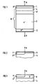
- FIG. 1 shows a power semiconductor component in which an anode-side structure 1, a base zone B and a cathode-side structure 2 are provided in sequence in a semiconductor base body.
- the anode-side structure consists only of a p+-doped region 1 which is electrically conductively connected to the anode connection A and the cathode-side structure has an n+-doped region 2 which is electrically conductive with the cathode connection K. connected is.
- the p+-doped region 1 has a thickness of ⁇ 30 microns and a doping concentration at the anode-side edge of 1015 to 1019 cm ⁇ 3.
- the n+-doped ⁇ region 2 has a thickness of ⁇ 30 ⁇ m and a doping concentration at the edge of the cathode of 1018 to 1020 cm ⁇ 3.
- the base zone B consists, in order and on the anode side, of a first further layer 4, an optionally provided and indicated by dashed lines, second further layer 4 'and a layer 3 of an n + -doped substrate material.
- the thickness of the layer 3 of the n ⁇ -doped substrate material is usually about 100 microns per kilovolt reverse voltage and the substrate material has a basic doping of 8 * 1012 to 2 * 1014 cm ⁇ 3.
- the first further layer 4 of the base zone is provided and consists of a p ⁇ -doped layer 4 between 30 and 120 ⁇ m thick which, in comparison to the at least one p+-doped Area 1 of the anode-side structure is weaker, for example with an anode-side edge concentration of 8 * 1012 to 2 * 1014 cm ⁇ 3, doped.
- a typical thickness of layer 4 is 100 microns and a typical edge concentration of layer 4 is 4 * 1013 cm ⁇ 3.
- a second further layer 4 ′ of base zone B is provided, which is weaker compared to the n ⁇ -doped substrate material, for example weaker by a factor of 0.1 in the anode-side edge concentration. doped n ⁇ ⁇ -doped layer.
- the total thickness of the two layers 4 and 4 ' corresponds to the above information for the individual layer 4, the layers 4 and 4' typically being approximately the same thickness.
- the first further layer 4 of the base zone which consists of a doped n ⁇ ⁇ -doped layer that is weaker compared to the n ⁇ -doped substrate material, for example, weaker by a factor of 0.1.
- the thickness of layer 4 is also between 30 and 120 microns and typically 100 microns.
- the anode-side structure does not necessarily have to exist in the form of a p+-doped layer (PiN diode) or a comparatively thin p ⁇ -doped layer (P-iN diode) provided over the entire surface, but can also have other anode-side structures to reduce the emitter efficiency, as they are, for example, from the contribution by M.
- Mehrotra et al. are known for themselves.
- the anode-side structure is designed in such a way that the further layer 4 of the base zone B, which adjoins a pbericht-doped region 1 'of the anode-side structure, is electrically conductively connected to the anode connection A ( Merged PiN / Schottky Diode).
- the thickness and marginal concentration of area 1 ' corresponds to area 1.
- two further anode-side structures for lowering the emitter efficiency are shown in dashed lines, which are designed such that the further layer 4 of the base zone B, which adjoins the p+-doped region of the anode-side structure, over an area 5 with is connected to the anode connection A, which is either made of a p ⁇ -doped material (Static Shielding Diode) which is weakly doped in comparison to the p vide-doped region 1 'of the anode-side structure, or of a metal / silicon alloy (soft and fast recovery diode) consists.
- a p ⁇ -doped material Static Shielding Diode
- metal / silicon alloy soft and fast recovery diode
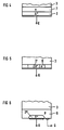
- FIG. 3 shows a further anode-side structure for increasing the emitter efficiency, which is designed such that both the p+-doped region 1 'of the anode-side structure and an additional p-doped region 6 of the anode-side structure, which is less doped in comparison, are electrically are conductively connected to the anode connection A.
- the additional p-doped region 6 is arranged such that the p+-doped region 1 'of the anode-side structure and the further layer 4 of the base zone B adjoining the anode-side structure are separated from one another, additional p-doped region 6 being weaker is doped as the p+-doped region 1 'of the anode-side structure.
- the contiguous area 1 'shown in FIGS. 2 and 3 is also conceivable in the form of a plurality of areas which are not directly contiguous.
- FIG. 4 shows an embodiment in which the cathode-side structure has a n-doped buffer layer 7 which is weaker compared to the n+-doped layer 2 of the cathode-side structure, for example 1014 to 2 * 1014 cm ⁇ 3, which layer between the layer 2 of the cathode-side structure and the layer 3 of the substrate material.
- FIG. 5 shows a further embodiment, in which the cathode-side structure has at least one n+-doped region 2 ′ and at least one n-doped region 8, which is weaker compared to it, for example from the basic doping to 1014 cm ⁇ 3, where the at least one less heavily doped region is in each case electrically conductively connected to the cathode connection K and directly adjoins the layer 3 of substrate material.
- the base zone B structured according to the invention shown in FIG. 1 and the various anode-side structures shown in FIGS. 1, 2 and 3 can be used both for diodes and for thyristors.
- FIG. 6 shows a part of a corresponding thyristor on the cathode side.
- An associated part of the thyristor on the anode side can be seen from FIGS. 1, 2 and 3.
- the thyristor differs from a corresponding diode only in that a p-doped gate layer 9, which is electrically conductively connected to a gate connection G, between the layer 3 made of the substrate material and at least one ntechnisch-doped region 2 ′′ of the cathode-side structure is provided.
- the thickness and the edge concentration of the area 2 ′′ correspond to the values for layer 2.
- curves 11.14 of the electric field strength are plotted against the location coordinate x, the x-coordinate starting at the anode connection A and ending at the cathode connection K, and the curves being shown in simplified form.
- the diagram also shows the critical breakdown field strength E crit , which is approximately 2 * 105 V / cm for silicon.
- the courses 11 and 12 correspond to the field strength courses in known power diodes, the courses being essentially triangular and the field strength lying directly at the cathode-side end of the layer 1.
- the field strength profile 11 applies to the steady state and the field strength profile 12 corresponds to the dynamic profile when switching off. It is noticeable here that the field strength gradient is increased in the course 12 and a higher maximum field strength occurs than in the course 11.
- This dynamic effect arises from the fact that electrons in the direction of the cathode and holes in the direction of the anode are sucked out of the pn junction during the transition into the blocking state.
- the uncompensated donor ions create a space charge zone, the space charge of which determines the field strength gradient in the space charge zone.
- the hole transport through the space charge zone increases the positive space charge and the field gradient increases accordingly.
- the maximum field strength of the course 11 that is to say for the stationary case of the known diode, is chosen equal to the critical breakdown field strength E crit
- the maximum value of the course 12 that is to say in the dynamic case of the known diode, is greater than the critical field strength and a so-called dynamic avalanche breakdown D occurs, in which new charge carriers are generated by charge carrier multiplication.
- the curves 13 and 14 are also shown for a diode according to the invention, the integral of the field strength between the limits A and K, ie. H. the applied reverse polarity voltage is the same for all four curves.
- the maximum value of the electric field strength is considerably lower both in the course 13, that is in the stationary case, and in the course 14, that is to say in the dynamic case, than in the courses 11 and 12. The reason for this is that, due to the layer 4 and, if appropriate existing layer 4 ', a field flattening occurs by reducing the space charge in this area, which compensates for the steeper field course in layer 3 caused by the hole transport.
- the maximum field strength is no longer reached at the cathode-side end of layer 1, but at the cathode-side end of layer 4 or optionally layer 4 '.
- FIG. 8 shows the time profile 15 of the reverse current for a diode according to the invention and the dashed line shows the time profile 16 of the reverse current for a comparable known diode when switching off, the cut-off voltage polarized to a blocking direction.
- a second reverse current peak arises due to the dynamic avalanche breakdown D and the reverse current is longer than zero for a longer period than in the course of 15. This is disadvantageous in particular at high cut-off voltages because of the large power loss.
- the change in the reverse current over time can change abruptly and lead to undesired voltage peaks in the case of inductive loads that may be present.
- Diodes according to the invention can advantageously be used as freewheeling diodes in motor control systems or the like and are typically designed for rated blocking voltages between 1200 V and 4500 V.
Landscapes
- Thyristors (AREA)
Applications Claiming Priority (2)
| Application Number | Priority Date | Filing Date | Title |
|---|---|---|---|
| DE4342482A DE4342482C2 (de) | 1993-12-13 | 1993-12-13 | Schnelle Leistungshalbleiterbauelemente |
| DE4342482 | 1993-12-13 |
Publications (1)
| Publication Number | Publication Date |
|---|---|
| EP0657945A2 true EP0657945A2 (fr) | 1995-06-14 |
Family
ID=6504887
Family Applications (1)
| Application Number | Title | Priority Date | Filing Date |
|---|---|---|---|
| EP94118692A Withdrawn EP0657945A2 (fr) | 1993-12-13 | 1994-11-28 | Dispositifs semi-conducteurs de puissance rapides à base structurée |
Country Status (3)
| Country | Link |
|---|---|
| EP (1) | EP0657945A2 (fr) |
| JP (1) | JPH07202226A (fr) |
| DE (1) | DE4342482C2 (fr) |
Cited By (2)
| Publication number | Priority date | Publication date | Assignee | Title |
|---|---|---|---|---|
| EP2320452A1 (fr) * | 2009-11-09 | 2011-05-11 | ABB Technology AG | Diode à récupération rapide et sa procédé de fabrication |
| US8912623B2 (en) | 2009-11-09 | 2014-12-16 | Abb Technology Ag | Fast recovery diode |
Families Citing this family (3)
| Publication number | Priority date | Publication date | Assignee | Title |
|---|---|---|---|---|
| DE102005031398A1 (de) * | 2005-07-05 | 2007-01-11 | Infineon Technologies Ag | Diode |
| DE102007001108B4 (de) | 2007-01-04 | 2012-03-22 | Infineon Technologies Ag | Diode und Verfahren zu ihrer Herstellung |
| US8809902B2 (en) * | 2011-10-17 | 2014-08-19 | Infineon Technologies Austria Ag | Power semiconductor diode, IGBT, and method for manufacturing thereof |
Family Cites Families (6)
| Publication number | Priority date | Publication date | Assignee | Title |
|---|---|---|---|---|
| US3943549A (en) * | 1972-03-15 | 1976-03-09 | Bbc Brown, Boveri & Company, Limited | Thyristor |
| GB2050694B (en) * | 1979-05-07 | 1983-09-28 | Nippon Telegraph & Telephone | Electrode structure for a semiconductor device |
| JPS5839070A (ja) * | 1981-08-31 | 1983-03-07 | Toshiba Corp | 半導体装置 |
| JPS5929469A (ja) * | 1982-08-11 | 1984-02-16 | Hitachi Ltd | 半導体装置 |
| DE3328521C2 (de) * | 1983-08-06 | 1985-11-14 | SEMIKRON Gesellschaft für Gleichrichterbau u. Elektronik mbH, 8500 Nürnberg | Gleichrichterdiode für hohe Sperrspannung |
| EP0144876B1 (fr) * | 1983-12-07 | 1988-03-09 | BBC Brown Boveri AG | Dispositif à semi-conducteurs |
-
1993
- 1993-12-13 DE DE4342482A patent/DE4342482C2/de not_active Expired - Fee Related
-
1994
- 1994-11-28 EP EP94118692A patent/EP0657945A2/fr not_active Withdrawn
- 1994-12-13 JP JP6309339A patent/JPH07202226A/ja not_active Withdrawn
Cited By (3)
| Publication number | Priority date | Publication date | Assignee | Title |
|---|---|---|---|---|
| EP2320452A1 (fr) * | 2009-11-09 | 2011-05-11 | ABB Technology AG | Diode à récupération rapide et sa procédé de fabrication |
| US8395244B2 (en) | 2009-11-09 | 2013-03-12 | Abb Technology Ag | Fast recovery diode |
| US8912623B2 (en) | 2009-11-09 | 2014-12-16 | Abb Technology Ag | Fast recovery diode |
Also Published As
| Publication number | Publication date |
|---|---|
| JPH07202226A (ja) | 1995-08-04 |
| DE4342482C2 (de) | 1995-11-30 |
| DE4342482A1 (de) | 1995-06-14 |
Similar Documents
| Publication | Publication Date | Title |
|---|---|---|
| EP0200863B1 (fr) | Dispositif à semi-conducteur comportant des structures de type thyristor et diode | |
| EP0621640B1 (fr) | Dispositif de puissance à semi-conducteur | |
| DE69325608T2 (de) | Halbleiterbauelement mit einem Schutzmittel | |
| EP2740155B1 (fr) | Diode pin schottky à superjonction | |
| DE4011509A1 (de) | Bidirektionales, abschaltbares halbleiterbauelement | |
| EP0760528B1 (fr) | Dispositif semi-conducteur sur base de silicium avec bordure à blocage élevé | |
| EP0043009A2 (fr) | Commutateur commandé par semiconducteur | |
| DE102012201911A1 (de) | Super-Junction-Schottky-Oxid-PiN-Diode mit dünnen p-Schichten unter dem Schottky-Kontakt | |
| DE102011087591A1 (de) | Hochspannungs-Trench-Junction-Barrier-Schottkydiode | |
| DE2832154C2 (fr) | ||
| DE3521079A1 (de) | Rueckwaerts leitende vollsteuergate-thyristoranordnung | |
| DE4228832C2 (de) | Feldeffekt-gesteuertes Halbleiterbauelement | |
| DE69835052T2 (de) | Kontakt auf P-Typ Gebiet | |
| EP0430133B1 (fr) | Dispositif semi-conducteur de puissance comportant des courts-circuits d'émetteur | |
| EP0709899A2 (fr) | Diode semi-conductrice avec injecteur d'électrons | |
| DE4342482C2 (de) | Schnelle Leistungshalbleiterbauelemente | |
| DE4337209A1 (de) | Abschaltbarer Thyristor | |
| DE3942490C2 (de) | Feldeffekt-gesteuertes Halbleiterbauelement | |
| EP1488465B1 (fr) | Structure semiconductrice comportant un element de commutation et un element marginal | |
| EP0206350A2 (fr) | Thyristor à épaisseur de base réduite | |
| DE69432111T2 (de) | Bipolartransistor mit isoliertem Gate | |
| DE10049354A1 (de) | Halbleiterbauelement | |
| DE10161139B4 (de) | Halbleiteraufbau mit Schottky-Diode für Rückwärtsbetrieb | |
| DE112024002502T5 (de) | Halbleiterbauelement | |
| CH652863A5 (de) | Schaltvorrichtung mit einem substrat aus halbleitermaterial und schaltereinrichtung mit mehreren schaltvorrichtungen. |
Legal Events
| Date | Code | Title | Description |
|---|---|---|---|
| PUAI | Public reference made under article 153(3) epc to a published international application that has entered the european phase |
Free format text: ORIGINAL CODE: 0009012 |
|
| AK | Designated contracting states |
Kind code of ref document: A2 Designated state(s): CH DE FR GB IT LI |
|
| STAA | Information on the status of an ep patent application or granted ep patent |
Free format text: STATUS: THE APPLICATION IS DEEMED TO BE WITHDRAWN |
|
| 18D | Application deemed to be withdrawn |
Effective date: 19970601 |