EP0658384A2 - Procédé et dispositif pour fabriquer des jantes de roues de véhicules - Google Patents
Procédé et dispositif pour fabriquer des jantes de roues de véhicules Download PDFInfo
- Publication number
- EP0658384A2 EP0658384A2 EP94309315A EP94309315A EP0658384A2 EP 0658384 A2 EP0658384 A2 EP 0658384A2 EP 94309315 A EP94309315 A EP 94309315A EP 94309315 A EP94309315 A EP 94309315A EP 0658384 A2 EP0658384 A2 EP 0658384A2
- Authority
- EP
- European Patent Office
- Prior art keywords
- die
- rim
- arrays
- cone
- cone cam
- Prior art date
- Legal status (The legal status is an assumption and is not a legal conclusion. Google has not performed a legal analysis and makes no representation as to the accuracy of the status listed.)
- Granted
Links
Images


Classifications
-
- B—PERFORMING OPERATIONS; TRANSPORTING
- B21—MECHANICAL METAL-WORKING WITHOUT ESSENTIALLY REMOVING MATERIAL; PUNCHING METAL
- B21D—WORKING OR PROCESSING OF SHEET METAL OR METAL TUBES, RODS OR PROFILES WITHOUT ESSENTIALLY REMOVING MATERIAL; PUNCHING METAL
- B21D53/00—Making other particular articles
- B21D53/26—Making other particular articles wheels or the like
- B21D53/30—Making other particular articles wheels or the like wheel rims
-
- Y—GENERAL TAGGING OF NEW TECHNOLOGICAL DEVELOPMENTS; GENERAL TAGGING OF CROSS-SECTIONAL TECHNOLOGIES SPANNING OVER SEVERAL SECTIONS OF THE IPC; TECHNICAL SUBJECTS COVERED BY FORMER USPC CROSS-REFERENCE ART COLLECTIONS [XRACs] AND DIGESTS
- Y10—TECHNICAL SUBJECTS COVERED BY FORMER USPC
- Y10T—TECHNICAL SUBJECTS COVERED BY FORMER US CLASSIFICATION
- Y10T29/00—Metal working
- Y10T29/49—Method of mechanical manufacture
- Y10T29/49481—Wheel making
- Y10T29/49492—Land wheel
- Y10T29/49524—Rim making
- Y10T29/49529—Die-press shaping
Definitions
- the present invention relates to a method and apparatus for use in the manufacture of wheel rim members, and more particularly for truing roundness and size of tire-carrying wheel rims by permanent deformation expansion of the same.
- the present invention may be employed for expanding various types and sizes of vehicle wheel rims, it finds particular utility in expanding rims of the one-piece drop-centre type.
- a strip of sheet metal stock cut to suitable width and length is coiled and the strip ends flash-butt-welded together to provide an annular element.
- the axial end portions of the annular element are flared outwardly in a flaring station and then the flared annular element is roll-formed in one or more roll-forming machines to provide a rim element which has a rough drop-centre rim contour and which is slightly diametrically undersize relative to rim final dimensions.
- the rolled rim element is then conveyed to a shaping apparatus, usually called an expander, in which the rim element is diametrically expanded by a segmental expansion die fixture to circumferentially stretch the material beyond its yield point to thereby impart a permanent set to the material at an enlarged finished diameter.
- a shaping apparatus usually called an expander
- Rim expander apparatus of this character is described in US-A-1 926 400 and in US-A-5 010 759.
- Such rim expanding apparatus is provided with radially movable shaping die segments arranged in a circular array and cooperating at their radially outermost surfaces to form an annular peripheral surface corresponding to the cross-sectional contour of the rim to be expanded.
- the die segments are moved from their innermost retracted positions radially outwardly into engagement with the rim to diametrically expand the rim a predetermined amount to circumferentially stretch and permanently set the rim material to thereby both accurately size and impart a true circular contour to the rim.
- Such rim expanders developed for use with channel or drop-centre wheel rims are typically provided with two sets of axially opposed segmental die fixtures adapted to be mounted one each on fixed and movable members of a horizontal or vertical axis press.
- the press mounted die fixtures are thus coaxially relatively movable and axially separable from one another to permit loading of a rim workpiece therebetween.
- the opposed fixtures are respectively inserted into the inboard and outboard ends of the rim and are closable together into abutment at a press parting line located by reference to the minimum inside diameter of the rim element to be worked.
- the jaws or die segments need only have a short travel on their radial expansion working stroke despite the relatively large difference between the internal and external diameters of the typical drop-centre rim.
- a short radial travel stroke of the die segments is important in reducing the amount of circumferential spacing between the individual sizing die segments of the segmental die in their fully expanded condition so as to minimize the rim "chording" phenomenon induced by the circumferential gaps between the expanded die segments.
- the closed die set parting line location may be arranged to intersect the mid-point of the drop-centre well, whereby each die set would engage the corresponding half of the rim well. More typically, however, one of the die sets is designed with its sizing die segments to engage the entire inner surface of an annular zone of the rim including one of the bead seats, an associated tire bead retaining flange and the drop-centre well, and to abut the cooperating die set at a parting line located at the edge of the rim well remote from such bead seat. Hence, this die set expands the drop-centre well and one associated rim bead seat and flange, whereas the other opposed die set only expands the opposite bead seat and its associated flange.
- the two opposed segmental die sets may be individually expanded by two coaxially opposed and movable conical wedge expanding members, such as described in US-A-3 706 120 (FIG. 8) and in the aforementioned US-A-5 010 579 (FIGS. 4 and 5).
- each die segment is removably secured on a radially movable die holder of the die set to permit interchanging the same for expanding different types and sizes of rims.
- each die set typically may contain as many as sixteen die segments, it often requires up to two hours or more for skilled set-up personnel to shim adjust the die set to change rim bead seat diameters (and thus the associated rim well diameter as a dependent variable). Obviously, this is a costly procedure in terms of both labour and production line down-time.
- rim well inside diameter and either or both of the rim bead seat outside diameters are not independently adjustable relative to one another.
- Such dimensions of each of these three critical elements of the rim, as well as their roundness and concentricity relative to one another, are all well recognized as important quality control parameters which must be closely monitored in modern high speed mass production of wheel rims and disc assemblies.
- the inside diameter of the rim well must be closely controlled because, after the rim expansion station operation, the rounded and sized rim is conveyed to a disc assembly station where a wheel disc is telescopically press fit into the rim well. This rim and disc assembly is then conveyed to a subsequent station where the disc is welded to the rim.
- roundness and precise dimensional control of the rim well inner periphery are essential for optimizing the disc press-in production operation regardless of the roundness and diameter of the inboard and outboard bead seats of the rim.
- each of the rim bead seats be finished to their outside diametrical dimensions within very close tolerances in a uniform manner.
- the bead seats also must be both round and concentric with one another as well as with the inner periphery of the rim well within very close tolerances.
- an object of the present invention is to provide an improved rim expand sizing method, and an improved apparatus for performing the method, which overcome the aforementioned problems in a reliable and economical manner.
- Another object of the present invention is to accomplish a substantial improvement in the manufacture of drop-centre wheel rims by providing a rim expand sizing apparatus capable of expanding rims to an overall predetermined size while at the same time insuring true forming and control of each of the three critical dimensional zones of the drop-centre rim, namely (1) outboard bead seat outside diameter, (2) inboard bead seat outside diameter and (3) rim well inside diameter, to thereby produce a finished rim having these three zones in a round, mutually concentric and desired dimensioned condition within very close tolerances regardless of the differences in design diameter of each of these three zones.
- Yet another object of the present invention which contributes materially in securing the foregoing advantageous results is to provide an improved rim expanding sizing segmental die apparatus having three sets of radially moving expanding die segments wherein each set is adjustable independently of the other two sets but operable conjointly to individually respectively expand the rim outboard and inboard bead seats and rim well.
- a further object of the present invention is to provide an improved rim expand sizing apparatus having opposed multiple arrays of radially expandable segmental dies for separately expanding different portions of a wheel rim and wherein each die array is rapidly, accurately and economically adjustable for set-up independently of the remaining die array or arrays without the need for shimming and/or re-shimming the individual die elements or jaws in either initial or running set-up adjustment of each die array.
- Still another object is to provide an improved rim expander of the aforementioned character in which each of the die arrays of the multiple die sets of the expander die is individually and separately adjustable by an improved set-up mechanism operably coupled for access and driving control exteriorly of the rim sizing apparatus such that set-up adjustment can be performed without the use of shims and without requiring access to the individual die arrays.
- Yet another object is to provide an improved rim expander of the aforementioned character having a feedback mechanism providing automatic rim sizing set-up adjustment on a selective basis of one or more of the multiple arrays of expandable segmental dies of the expansion die set, and under closed loop control on a running basis from rim to rim during production to thereby compensate for variations occurring during production and to better maintain precise and uniform control of rim size and other geometrical rim parameters.
- a wheel rim expander sizing apparatus constructed in accordance with the present invention may have a vertical orientation wherein a conical wedge die expander extends on a vertical axis and the segmental die sets are mounted as rim expand tooling in opposed vertically separable punch and die platens of a press.
- a horizontal orientation is utilized wherein the conical wedge expander extends in a horizontal direction in a horizontally separable headstock and tailstock type rim expander machine.
- rim expanding apparatus constructed in accordance with the invention may be employed advantageously in expanding rims of various cross-sectional contours and sizes.
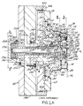
- FIGS. 1A and 1B for the purpose of illustrating that the rim expanding apparatus of the present invention definitely solves existing problems in the high volume, rapid mass production manufacture of drop-centre rims, such apparatus, generally designated as 10 in FIGS. 1A and 1B, is shown as employed in connection with this latter type of rim.
- the terms "outboard” and “inboard” are used for purposes of convenience in description rather than by way of limitation, and refer to the orientation of the wheel rim structure relative to the vehicle on which it is mounted when in road wheel use.
- Rim 20 has the usual outboard tire bead retaining flange 22, outboard tire bead seat 24, outboard safety hump 26 (FIG. 1B), drop-centre well 28, inboard safety hump 30, inboard tire bead seat 32 and inboard tire bead retaining flange 34 (FIG. 1A).
- rim expanding fixture 10 comprises a headstock segmental dual die set 40 (FIG. 1A) and a tailstock segmental single die set 42 (FIG. 1B) respectively mounted on the headstock 44 and tailstock 46 of a conventional horizontal-type rim expanding machine.
- Die sets 40 and 42 are mounted for movement by the machine and relative to each other along a common centre line horizontal axis 48 of the machine.
- Headstock die set 40 comprises two independent circular arrays of jaws or die segments 114 and 90, respectively, constructed and arranged as set forth in more detail hereinafter to form a rim-well-expand segmental die set array 50 and a rim-inboard-bead-seat-expand segmental die set array 52.
- Tailstock die set 42 comprises a circular array of die segments 170 cooperating to form a rim outboard-bead-seat-expand segmental die set array 54 (FIG. 1B) carried on tailstock 46 (FIG. 1B).
- die array 54 abuts die array 50 at the fixture parting line P/L.
- the peripheral surfaces of die arrays 54, 50 and 52 together correspond in configuration to the cross-sectional contour of the radially inwardly facing surfaces of rim 20 as and when expanded to finished form (FIGS. 1A and 1B).
- the individual die segments 114, 90 and 170 of die arrays 50, 52 and 54, respectively, are identical with one another within a given array. Die segments 114, 90 and 170 are preferably readily removably secured in place so as to permit expediently interchanging the same for other die segments of different sizes and configurations so that the same machine can be used for expanding different types and sizes of rims.
- the illustrated embodiment of the rim expanding fixture is constructed and arranged for use with a single-type expanding conical wedge assembly 60 which is fixed at one end to headstock 44 for cantilever support therefrom.
- Wedge assembly 60 thus is adapted to extend horizontally coaxially through both headstock fixture 40 and tailstock fixture 42, and functions upon movement of fixtures 42 and 40 as a unit to the left (as viewed in FIGS. 1 and 2) to operably slidably engage the segmental die fixtures 40 and 42 and, by a wedging action, force the die arrays 50, 52 and 54 radially outwardly conjointly into expanding engagement with rim 20.
- Tailstock 46 and fixture 42 carried thereon are separable in the machine cycle from headstock 44 and fixture 40 carried thereon by a distance sufficient to permit a rolled rim workpiece to be conveyed into loading position therebetween. Closing movement of tailstock 46 (to the left as viewed in FIGS. 1 and 2) will cause the rolled rim workpiece to be telescoped loosely over the retracted die arrays 50, 52, 54 as the tailstock die array 54 moves into abutting engagement with the headstock die array 50, as shown in FIG. 2 (rough rolled rim workpiece not shown). In this initially closed, loaded condition of fixtures 40 and 42, the three die arrays 50, 52 and 54 form a complete segmental die assembly and are in their fully radially retracted position shown in FIG. 2.
- tailstock 46 to the left causes its fixture 42 to push headstock fixture 40 along with it so that fixtures 40 and 42 move axially as a unit along wedge expander 60 through a predetermined working stroke of axial travel designated "W/SA" in FIG. 2.
- Such movement of both fixtures 42 and 40 leftward and co-axially relative to wedge 60 causes the wedge to slidably engage and force the three die arrays 50, 52 and 54 radially outwardly as a unit, through a corresponding predetermined working stroke radial travel "W/SR" (FIG. 2), into radially expanding engagement with the rolled rim workpiece to size and shape expand the same into finished rim 20.
- headstock fixture 40 comprises a circular array of a plurality of rim-inboard die holders 62, e.g., sixteen in number herein and identical with one another (FIGS. 1A and 2).
- Holders 62 each have outer and inner flanges 64 and 66, respectively, slidably captured by keeper rings 68 and 70 for holding die holder 62 in sliding abutment with a circular keyway plate 72.
- the lowermost inboard die holder 62' of this array is sectioned in FIG.
- FIG. 1A to illustrate a key 76 removably affixed thereto and slidably received in an associated keyway 78 of ring plate 72 (it being understood that each of the remaining inboard die holders 62 are likewise keyed for radial sliding movement against ring plate 72).
- An endless tension coil spring 80 is trained through a groove 82 in each holder 62 so as to encircle and yieldably bias the array of holders 62 radially inwardly toward the fully retracted position thereof shown in FIG. 2.
- Each die holder 62 is provided with stepped locating surfaces 84 and 86 and a shoulder 88 against which is seated an associated rim-inboard die segment 90.
- Each segment 90 is removably affixed to its associated holder 62 by a pair of machine screws 92, and is provided with a slot 94 which registers with a locating pin 96 fixed in the associated inboard die holder 62.
- the headstock rim expansion fixture 40 is made up of the two segmental rim expansion die arrays 50 and 52 operably coupled for ganged, unitary movement axially of the fixture but capable of movement radially of the fixture independently of one another.
- Die array 52 is operable to engage only the radially inwardly facing surface of an annular rim inboard zone of the rolled rim workpiece, this inboard zone extending inboard from a radial plane located just inboard of rim well 28 to and including inboard rim flange 34.
- Die segments 90 are thus contoured on their radially outward facing surfaces to expand form the safety hump 30, inboard bead seat 32 and inboard tire bead retaining flange 34 of rim 20.
- die array 50 is constructed and arranged to engage solely the radially inwardly facing surface of the annular rim well zone containing rim well 28 to expand form only the same.
- Die array 50 comprises a plurality (e.g., sixteen) of die holders 100, one carried on each of the inboard holders 62, and each having a dove tail 102 slidably radially of the array in a dove tail slot 104 in the outer face of the associated holder 62.
- An endless tension coil spring 106 seats in a groove 108 of each holder 100 and encircles the entire array of holders 102 for yieldably biasing them radially inwardly to the retracted position shown in FIG. 2.
- Each holder 100 is provided with a locating surface 110 and a slightly inclined undercut shoulder 112 for removably seating thereon an associated rim well expand die segment 114.
- Each die segment 114 is removably affixed to its associated holder 100 by a pair of machine screws 116 and is provided with a locating slot 118 which registers with a locating pin 120 fixed in the associated holder 100.
- the array of well die segments 114 although gang supported by their associated holders 100 on the associated inboard holders 62 for movement axially as a unit therewith, are nevertheless freely movable radially relative to inboard die segments 90.
- the radially adjusted set-up positions of the well expand die array 50 and rim inboard die array 52 can be varied independently of one another, either by conventional manual shimming practice or preferably by utilizing the wedge cone adjustment features described hereinafter.
- tailstock fixture 42 comprises a plurality (e.g., sixteen) of die holders 130 each with outer and inner flanges 132 and 134, respectively, slidably clamped by a keeper ring 136 and by a flange 138 of a guide plug 140 into radial sliding abutment against a keyway plate 142.
- each holder 130 has a keyway 148 which slidably receives a key 150 affixed to plate 142.
- Guide plug 140 is removably fastened by a machine screw 154 threaded into a platen 152 of tailstock 46.
- Plate 142 has a centre hole 156 receiving a nose 158 of plug 140, and a shoulder 160 of plug 140 clamps plate 142 against platen 152.
- Each die holder 130 has a pair of locating surfaces 162 and 164 and an undercut shoulder 166 against which an individually associated outboard die segment 170 is removably seated.
- Each die segment 170 is removably affixed to its associated holder 130 by a pair of machine screws 172, and has a locating slot 174 registering with a locating pin 176 affixed to the associated die holder.
- the inboard faces 180 of each outboard die segment 170 define a common radial plane adapted to abut at the parting line P/L the corresponding faces 182 of the associated well die segments 114 in the closed condition of fixtures 40 and 42.
- rim outboard expand segmental die array 54 also is radially adjustable for set-up independently of either or both the rim well expand die array 50, and rim inboard expand die array 52.
- Die segments 170 are identically configured on their outer surfaces to engage the radially inwardly facing surface of the annular zone outboard of rim 20, extending outboard from the outboard edge of rim well 28, and to thereby expand form the rim outboard safety hump 26, outboard bead seat 24 and associated rim outboard tire bead retaining flange 22.
- Each of outboard die holder 130 is provided with a groove 184 to receive an encircling endless tension coil spring 186 for yieldably biasing the array of outboard die holders to the retracted position as shown in FIG. 2.
- the expanding wedge mechanism 60 carries three independently adjustable expanding cone cams 200, 202 and 204 (FIGS. 1 and 2) , respectively, individually associated with die arrays 52, 50 and 54.
- the rim outboard expand cone 204 is threadably received on the threaded free end 208 of a solid centre shaft 210 of wedge mechanism 60.
- Centre shaft 210 rotatably carries inner and outer concentric sleeves 212 and 214 constructed and arranged at their respective free ends 216 and 218 in a stepped, axially offset receding array relative to protruding shaft end 208 (FIG. 1A).
- Sleeves 212 and 214 are externally threaded at 220 and 222, respectively, to threadably receive, respectively, thereon cones 202 and 200.
- outer shaft 214 is rotatably journalled in a pair of axially spaced bushings 230 and 234.
- Bushing 230 is cantilever mounted by machine screws 236 in a socket 238 of a mounting plate 240 which in turn is fastened by machine screws 242 in a socket 244 of a platen 246 of headstock 44.
- Bushing 234 is supported in a bore 250 of a flanged cup housing 252 fastened by machine screws 254 to platen 246.
- Inner sleeve 212 is journalled for rotation in the spaced internal lands 215 of outer sleeve 214, and likewise centre shaft 210 is journalled for rotation in the spaced internal lands 217 of inner sleeve 212.
- Three worm gear drives are provided in housing 252 for individually rotating shaft 210 and sleeves 212, 214.
- a worm helical gear 256 is affixed to the housing end 258 of shaft 210, and likewise worm helical gears 260 and 262 are respectively affixed to the axially stepped back housing ends of sleeves 212 and 214.
- These three gears are captured in spaced apart relationship between bushing 234 and the end wall of housing 252 by interposed journal spacers 264, 266 and 268.
- This housing and bushing mounting configuration thus secures wedge expanding mechanism 60 in cantilever fashion to the fixed platen 246 of headstock 44.
- wedge mechanism 60 in the closed condition of die fixtures 40 and 42 the free end of wedge mechanism 60 is slidably supported by tailstock 46 due to a hollow nose sleeve portion 270 of outboard expand cone 204 being coaxially slidably received in a guide bore 272 of plug 140.
- tailstock 46 is retracted away from headstock 44 in order to load a rolled rim workpiece, or to unload a finished sized rim 20, nose sleeve 270 is completely withdrawn from guide plug 140.
- wedge mechanism 60 is solely cantilever supported by the headstock 44.
- cam nose 270 is partially inserted into guide bore 272 of plug 140 to provide radial load bearing support and alignment for the free end of wedge mechanism 60 during segmental die radial expansion travel in working stroke W/SR.
- Each of the cone cams 200, 202 and 204 comprises a solid disc having a circular peripheral array of sixteen inclined flat external camming surfaces 274, 276 and 278, respectively, individually slidably mating with complementary inclined internal camming surfaces 280, 282 and 284 of the associated die holders 62, 100 and 130.
- the slidable interengagement of these respective camming surfaces of the cone cams 200, 202 and 204 and associated die holders 62, 100 and 130 produces by cam wedging action the radial expansion of, and permits the radial contraction of, the die holders in response to relative axial movement between the cone cams and associated die holders during travel of tailstock 46 toward and away from headstock 44 in axial working stroke W/SA.
- Cone cams 200 and 202 are keyed against rotation relative to headstock 44 by a pin 288 (FIG. 1A) fixed at one end to bushing 230 and extending slidably through a bore 290 in cone cam 200 and a bore 292 in cone cam 202.
- Cone cam 204 is likewise keyed against rotation relative to headstock 44 (FIGS. 1A and 1B) by a pin 294 fixed at one end in cone cam 204 and slidable at the other end in a bore 296 in cone cam 202.
- each cone cam 200, 202 and 204 is individually threadably movable axially of wedge mechanism 60 to any desired set-up location by individually rotating its associated carrier sleeves 214, 212 and shaft 210, respectively.
- cam carriers thus serve both as cam supports and as set-up adjustment lead screws for selectively adjusting each cone cam.
- the precision adjusted axial position of each cone cam relative to wedge mechanism 60 in turn determines the end limit of outward radial travel of the associated die holder in its working stroke W/SR for a given axial working stroke W/SA, to thereby set the finished diametrical dimension of each of the three zones of rim 20 as individually expanded by the three cone cams.
- each of the helical gears 256, 260 and 262 are rotatably driven by an associated worm gear fixture mounted in housing 252. As best seen in FIGS.
- the worm gear drive for set-up adjustment of the inboard cone cam 200 comprises a worm gear 300 fixed on a drive shaft 302 journalled at its inner end 304 in a bore provided in housing 252 and protruding at its outer end 306 tangentially from the exterior of the housing.
- Gear 300 meshes with gear 262 to thereby rotatably drive outer sleeve 214 for threadably shifting cone cam 200 axially of wedge mechanism 60 to a desired adjusted set-up position.
- two additional identical worm screw driving fixtures are mounted at 120° spacing in housing 252 (as shown only partially in FIG.
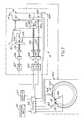
- each of the worm gears may be manually rotated to provide set-up adjustment, it is preferred to provide as shown schematically in FIG. 7, conventional electrical stepper motor or servo motor drives 307, 309 and 311 individually coupled one to each of the worm gear drive shafts 306, 308 and 310, respectively, and electronically controlled by a conventional servo motor control system 313 for ease and accuracy, as well as reliability of operation.
- a servo motor cam control system may be designed for open loop operational control of the cone cam set-up adjustment by operator input 315, it is preferred to provide a closed loop feedback control system for individual and/or conjoint set-up adjustment of the cone cams.
- sensor 320 has a threaded mounting sleeve 326 threaded through a mounting bracket 328 which in turn is fastened to the end face of a mounting cavity in bushing 230, sleeve 326 being further secured by a lock nut 330.
- a sensing probe 332 of sensor 320 protrudes axially into a cavity 334 in cone cam 200 and is biased into yieldable abutment with the cavity end wall.
- the electrical leads 336 for sensor 320 are fed through the headstock 44 through bore 325 and openings 338, 340, 342 and 344 provided, respectively, in mounting plate 240, plate 246, housing 252 and back plate 346 of headstock 44.
- Sensors 322 and 324 likewise have sensing probes, 348 and 350, which respectively extend through suitable passageways (not shown), one in cone cam 200 for probe 348, and the other through both cone cams 200, 202 for probe 350.
- Probes 348 and 350 respectively yieldably abut the headstock sides of cone cams 202 and 204.
- the three position sensor leads 336, 352 and 354 are suitably operably coupled to a conventional electronic control panel in the computer control system 313 provided with a suitable visual display 317, as will be well understood by those skilled in the art and therefore shown only functionally herein.
- Each of the sensing probes 320, 322 and 324 thus is operable to provide an output signal indicative of the position of its associated cone cam 200, 202, and 204 axially of wedge mechanism 60.
- This signal in turn is processed through suitable control circuitry 313 to control the servo motor drives 307, 309, 311 of each cone cam lead screw 214, 212, 210.
- the desired end limit of radial outward travel of each array 50, 52 and 54 of die segments may be conveniently programmed into the set-up adjustment of the rim expanding mechanism of the invention.
- a conventional feedback control system may be advantageously provided to augment the set-up adjustment in a rim manufacturing production line.
- a suitable commercially available rim measuring station 360 may be installed immediately downstream of the rim sizing apparatus 10, such as a commercially available type of rim radial run-out measurement system similar to that described in US-A-3 951 563. With such rim measuring equipment 360, the finished dimensions of each of the three aforementioned critical diametrical dimensional parameters of rim 20 may be 100 percent measured and continuously monitored as each rim emerges from the rim expand station. Thus, any deviations from the desired diametrical and/or radial run-out tolerances of the rim outboard and inboard bead seats 24 and 32 as well as in rim well 28 will be detected immediately after each work cycle of the rim expand apparatus 10.
- the finished rim 20F is shown loaded in measuring station 360 and, with a portion of the rim broken away to illustrate the finished outboard bead seat 24, inboard bead seat 32 and rim well 28.
- Electronic dimension sensing gauges 362, 364 and 366 are operably provided in association with outside surfaces of the bead seats and the inside surface of the rim well. Sensors 362, 364 may either run on these surfaces of revolution as rim 20F is rotated by associated conventional rim fixturing of station 360, or three suitable apparatus circumferentially spaced arrays of such sensors may be utilized in a non-rotary fixture set-up.
- the set-up control system 313 is suitably provided with conventional information processing circuitry for feedback of this information from sensors 362, 364, 366 of the measuring station 360 to the servo motors 307, 309, 311 for controlling the cam set-up of the rim expanding apparatus 10 to suitably adjust individually one or more of the cone cams 200, 202 and/or 204 as required to compensate for the detected deviation in the previously just-finished rim 20F.
- Such automatic micro adjustment requires only a fraction of a second and preferably is performed through the feedback control circuitry 320-324, 362-366 and 313 and servo motor drives 307, 309, 311 of the cone cam lead screws 214, 212, 210 as a running adjustment on each piece during production.
- each of the three die arrays 50, 52 and 54 may be separately, either sequentially or simultaneously, adjusted radially of the tooling axis or centre-line C-L.
- stroke W/SA is a pre-set distance as conventionally provided in the set-up adjustment of the rim expanding machine or press carrying the tooling apparatus 10 of the invention.
- This axial work stroke motion of the assembly fixtures 40, 42 toward headstock 44 is yieldably resisted by a suitable conventional press cushion mechanism, herein illustrated as an air spring provided by a piston plate 400 carried in headstock 44.
- Piston 400 is slidably mounted on bushing 230 at its centre opening 402 and slidably mounted at its outer periphery 404 in a ring cylinder 406 suitably fixed to platen 246. Piston 400 has fixed thereto the holder guide clamps 68 and 70 so that the entire headstock die fixture assembly 40 is carried on piston 400 for axial movement therewith.
- FIGS. 1A and 1B show fixtures 42 and 40 at their end limit of expansion work stroke travel axially along wedge mechanism 60, as also will be seen by comparing the bottomed condition of nose 270 in plug 140 illustrated in FIG. 1B to the retracted position of these parts at the beginning of the work stroke shown in FIG. 2.
- the inclined holder cam surfaces 280, 282, 284 slidably forced axially along and radially outwardly on the associated cone cam surfaces 274, 276, 278, thereby concurrently forcibly driving the associated die holders 62, 100, 130 radially outwardly by a wedging action to a predetermined radial outer travel limit, as indicated by the radial expansion working stroke labelled W/SR in FIG. 2.
- the metal material of the undersized rolled rim workpiece is circumferentially stretched beyond its yield point by the arrays of segmental expansion dies 90, 114, 170 and thus the rim material takes a permanent set at its finished expanded contour and dimensions as determined by these expansion dies.
- a travel limit cushion stop ring 408 is provided on piston 400 to limit axial movement of die fixture assembly 40 on its return stroke toward tailstock 46.
- the triple array 50, 52, 54 of individually adjustable segmental expansion dies as compared to the prior dual die arrays hitherto commonly utilized in rim production lines, now provides a separate die expansion array 50 for individually expanding the drop centre well 28 zone of the rim.
- Die array 50 is independently adjustable relative to the flanking arrays 52 and 54 which respectively expand the inboard flange 34 inboard bead seat 32 zone and the outboard flange 22 outboard bead seat 24 zone of rim 20.
- arrays 52 and 54 are independently adjustable relative to one another.
- each of these three annular rim zones can be separately controlled relative to one another to thereby enhance the size and shape dimensional control of the wheel rim in production.
- downstream defects in disc and rim assembly operations are reduced and a better finished product in terms of the rim and disc wheel assembly is obtained.
- Another important feature of the apparatus described is the provision in a multiple array expandable segmental die fixture (whether applied to a conventional dual array die fixture or to the improved three array die fixture of the present invention), of an expander cone 200, 202, 204 for each separate array 52, 50, 54, each of which is independently axially adjustable along the expander wedge mechanism 60 to individually vary the expansion limits of each array.
- the augmentation of the system by the proximity sensor feedback mechanisms 320, 322, 324 enables real-time, 100% monitoring and adjustment for each successive rim workpiece during a production run.
- control system FIG. 7 coupled to the set-up adjustment mechanism, running variations in stock material and thickness, tool wear and other factors tending to produce out of tolerance conditions in the rim sizing operation can be rapidly and economically compensated for at minimum cost and with reduced scrap. This in turn results in high quality, precision rim sizing in an economical manner at production line rates.
- the lead screw cone cam set-up adjustment mechanism as described above also can be programmed to be an active element in producing driving force for radial expansion of die arrays 50, 52, 54 supplemental to the main wedging force developed by expander 60 in response to the headstock-tailstock closing motion produced by the conventional main driving system of the rim expander machine.
- the cone cams can be driven to move axially within predetermined axial travel limits either before, during or after the fixtures 40 and 42 complete their relative working stroke motion W/SA.
- the rate and sequence of such cone cam working motion can also be readily computer programmed independently for each cone cam by suitably utilizing the above-described servo-motor control system 313 as a supplemental expansion drive system.
- the rim expansion sizing apparatus 10 also may be readily augmented with known rim anti-chording structure (not shown), such as providing teeth extending from the mutually facing surfaces of the die segments to mate with recesses defined by the teeth of the adjacent die segment such as described in US-A-3 575 035 (FIG. 11), 3 509 755 (FIG. 12) and 5 010 759 (FIGS. 3A and 3B), and/or anti--chording split rings encircling the arrays of expander die segments such as disclosed in US-A-3 382 699 (FIGS. 1, 2A and 2B) and 5 010 759.
- known rim anti-chording structure not shown
- suitable conventional die lubrication systems are preferably provided for the rim expander apparatus 10, such as exteriorly arranged encircling tubing and associated nozzles for power spray or gravity drip application of conventional liquid die lubricants to lubricate the hereinabove described sliding surfaces of die fixtures 40, 42 and expander 60.
Landscapes
- Engineering & Computer Science (AREA)
- Mechanical Engineering (AREA)
- Moulds For Moulding Plastics Or The Like (AREA)
- Tyre Moulding (AREA)
- Forging (AREA)
Applications Claiming Priority (2)
| Application Number | Priority Date | Filing Date | Title |
|---|---|---|---|
| US08/165,910 US5452599A (en) | 1993-12-14 | 1993-12-14 | Method and apparatus for producing vehicle wheel rims |
| US165910 | 1993-12-14 |
Publications (3)
| Publication Number | Publication Date |
|---|---|
| EP0658384A2 true EP0658384A2 (fr) | 1995-06-21 |
| EP0658384A3 EP0658384A3 (fr) | 1995-11-15 |
| EP0658384B1 EP0658384B1 (fr) | 2000-05-17 |
Family
ID=22600976
Family Applications (1)
| Application Number | Title | Priority Date | Filing Date |
|---|---|---|---|
| EP94309315A Expired - Lifetime EP0658384B1 (fr) | 1993-12-14 | 1994-12-14 | Procédé et dispositif pour fabriquer des jantes de roues de véhicules |
Country Status (7)
| Country | Link |
|---|---|
| US (1) | US5452599A (fr) |
| EP (1) | EP0658384B1 (fr) |
| JP (1) | JPH0871677A (fr) |
| BR (1) | BR9404974A (fr) |
| CA (1) | CA2137852A1 (fr) |
| DE (1) | DE69424512T2 (fr) |
| ES (1) | ES2145814T3 (fr) |
Cited By (3)
| Publication number | Priority date | Publication date | Assignee | Title |
|---|---|---|---|---|
| CN105057449A (zh) * | 2015-07-23 | 2015-11-18 | 厦门日上集团股份有限公司 | 一种轮辋扩张模具 |
| CN107225909A (zh) * | 2017-06-09 | 2017-10-03 | 陕西理工大学 | 一种变形车轮及传动装置 |
| CN107695237A (zh) * | 2017-10-23 | 2018-02-16 | 中国航发成都发动机有限公司 | 一种用于航空发动机管组件管端螺母缩口收压装置 |
Families Citing this family (10)
| Publication number | Priority date | Publication date | Assignee | Title |
|---|---|---|---|---|
| US7587825B2 (en) * | 2006-02-01 | 2009-09-15 | Hayes Lemmerz International, Inc. | Method for producing a wheel disc |
| US7559145B2 (en) * | 2006-02-01 | 2009-07-14 | Hayes Lemmerz International, Inc. | Method for producing a wheel disc |
| KR100765657B1 (ko) * | 2006-11-03 | 2007-10-10 | 기아자동차주식회사 | 타이어 장착 설비 |
| CN101804432B (zh) * | 2010-04-09 | 2013-11-13 | 潘卫民 | 轮辋内撑式滚圈机 |
| CN103736858B (zh) * | 2013-12-31 | 2015-12-30 | 浙江路得坦摩汽车悬架系统有限公司 | 一种内外压涨通用模块式减震器支架整形模 |
| CN103706680B (zh) * | 2013-12-31 | 2016-01-20 | 中信戴卡股份有限公司 | 改进的车轮圆度校正装置 |
| DE102016116758A1 (de) * | 2016-09-07 | 2018-03-08 | Thyssenkrupp Ag | Verfahren und Vorrichtung zur Herstellung von geformten, insbesondere flanschbehafteten Blechbauteilen |
| DE102016118418A1 (de) | 2016-09-29 | 2018-03-29 | Thyssenkrupp Ag | Verfahren zur Herstellung eines geformten Bauteils mit einem maßhaltigen Zargenbereich |
| CN108031764A (zh) * | 2017-12-08 | 2018-05-15 | 中国航发沈阳黎明航空发动机有限责任公司 | 一种管端精密缩径及整圆装置及方法 |
| CN107962910A (zh) * | 2017-12-26 | 2018-04-27 | 苏州贝尔纳德铁路设备有限公司 | 一种弹性车轮自动压装装置 |
Family Cites Families (30)
| Publication number | Priority date | Publication date | Assignee | Title |
|---|---|---|---|---|
| US3172787A (en) * | 1965-03-09 | Method of manufacturing detachable wheel rims | ||
| US442598A (en) * | 1890-12-09 | knight | ||
| US887727A (en) * | 1907-07-10 | 1908-05-12 | Us Stamping Co | Expander for sheet-metal utensils. |
| US1838892A (en) * | 1927-03-15 | 1931-12-29 | Budd Wheel Co | Method and machine for forming rings |
| US1926400A (en) * | 1932-02-03 | 1933-09-12 | Kelsey Hayes Wheel Corp | Apparatus for forming rim members |
| US1997323A (en) * | 1932-07-02 | 1935-04-09 | Lempco Products Inc | Method of expanding brake drums |
| US2122044A (en) * | 1936-07-16 | 1938-06-28 | President And Directors Of The | Carton assembling mechanism |
| US2292054A (en) * | 1939-01-10 | 1942-08-04 | Hydraulic Dev Corp Inc | Triple-acting press |
| US2442965A (en) * | 1944-09-15 | 1948-06-08 | Aluminium Company | Forming caps, closures, and the like |
| US2684103A (en) * | 1948-08-07 | 1954-07-20 | Serrick Corp | Metalworking apparatus |
| US2826161A (en) * | 1949-04-04 | 1958-03-11 | Kelsey Hayes Co | Material handling device |
| US2629421A (en) * | 1950-04-21 | 1953-02-24 | American Can Co | Method of producing container bodies |
| US2740450A (en) * | 1951-05-19 | 1956-04-03 | Grotnes Machine Works Inc | Combined flanging and beading machine for metallic drums |
| US3190134A (en) * | 1963-08-09 | 1965-06-22 | James E Sadler | Hub driven device and means and method for making the same |
| US3298218A (en) * | 1963-08-20 | 1967-01-17 | Kelsey Hayes Co | Method and apparatus for forming wheel rims and the like |
| US3349599A (en) * | 1964-09-16 | 1967-10-31 | Inland Steel Co | Method and apparatus for forming a beaded shell |
| US3382699A (en) * | 1965-03-11 | 1968-05-14 | Continental Can Co | Method and apparatus for threading closure caps |
| US3564898A (en) * | 1968-06-14 | 1971-02-23 | Grotnes Machine Works Inc | Shrink-forming apparatus with integral tooling |
| US3729795A (en) * | 1971-05-17 | 1973-05-01 | Wallace Expanding Machines | Method for forming metal wheels |
| US3706120A (en) * | 1971-06-14 | 1972-12-19 | Walter William Bulgrin | Method and apparatus for producing vehicle rims |
| AT311768B (de) * | 1972-06-09 | 1973-12-10 | Gfm Fertigungstechnik | Schnellhubschmiedepresse |
| SU483172A1 (ru) * | 1973-10-23 | 1975-09-05 | Предприятие П/Я В-2190 | Устройство дл сближени гофров |
| JPS5371673A (en) * | 1976-12-09 | 1978-06-26 | Hidaka Seiki Kk | Dies for manufacturing fin for heat exchanger |
| DE3318516A1 (de) * | 1983-05-20 | 1984-11-22 | Topy Kogyo K.K., Tokyo | Verfahren zur formgebung und zur bearbeitung eines scheibenrads und eine dafuer vorgesehene einrichtung |
| US4561275A (en) * | 1983-05-24 | 1985-12-31 | Tomy Kogyo Kabushiki Kaisha | Method of shaping and machining disc wheel and equipment therefor |
| US4809529A (en) * | 1987-10-20 | 1989-03-07 | Topy Kogyo Kabushiki Kaisha | Flaring apparatus for flaring a rim element |
| JP2588553B2 (ja) * | 1987-12-23 | 1997-03-05 | トピー工業株式会社 | 整形装置 |
| JPH035035A (ja) * | 1989-05-31 | 1991-01-10 | Honda Motor Co Ltd | ホイールリムのハンプ部成形装置 |
| JP2868602B2 (ja) * | 1990-10-04 | 1999-03-10 | トピー工業株式会社 | カール部を有する自動車ホイール用リムの成形装置 |
| DE4102139C1 (fr) * | 1991-01-25 | 1992-07-09 | Leifeld Gmbh & Co, 4730 Ahlen, De |
-
1993
- 1993-12-14 US US08/165,910 patent/US5452599A/en not_active Expired - Fee Related
-
1994
- 1994-12-12 JP JP6335225A patent/JPH0871677A/ja active Pending
- 1994-12-12 CA CA002137852A patent/CA2137852A1/fr not_active Abandoned
- 1994-12-13 BR BR9404974A patent/BR9404974A/pt not_active IP Right Cessation
- 1994-12-14 EP EP94309315A patent/EP0658384B1/fr not_active Expired - Lifetime
- 1994-12-14 ES ES94309315T patent/ES2145814T3/es not_active Expired - Lifetime
- 1994-12-14 DE DE69424512T patent/DE69424512T2/de not_active Expired - Fee Related
Cited By (5)
| Publication number | Priority date | Publication date | Assignee | Title |
|---|---|---|---|---|
| CN105057449A (zh) * | 2015-07-23 | 2015-11-18 | 厦门日上集团股份有限公司 | 一种轮辋扩张模具 |
| CN105057449B (zh) * | 2015-07-23 | 2017-04-12 | 厦门日上集团股份有限公司 | 一种轮辋扩张模具 |
| CN107225909A (zh) * | 2017-06-09 | 2017-10-03 | 陕西理工大学 | 一种变形车轮及传动装置 |
| CN107225909B (zh) * | 2017-06-09 | 2020-02-07 | 陕西理工大学 | 一种变形车轮及传动装置 |
| CN107695237A (zh) * | 2017-10-23 | 2018-02-16 | 中国航发成都发动机有限公司 | 一种用于航空发动机管组件管端螺母缩口收压装置 |
Also Published As
| Publication number | Publication date |
|---|---|
| JPH0871677A (ja) | 1996-03-19 |
| BR9404974A (pt) | 1995-08-08 |
| EP0658384B1 (fr) | 2000-05-17 |
| DE69424512T2 (de) | 2000-10-12 |
| US5452599A (en) | 1995-09-26 |
| ES2145814T3 (es) | 2000-07-16 |
| CA2137852A1 (fr) | 1995-06-15 |
| DE69424512D1 (de) | 2000-06-21 |
| EP0658384A3 (fr) | 1995-11-15 |
Similar Documents
| Publication | Publication Date | Title |
|---|---|---|
| EP0658384B1 (fr) | Procédé et dispositif pour fabriquer des jantes de roues de véhicules | |
| US5568745A (en) | Method and apparatus for making disc wheels and wheels made thereby | |
| CN114401803B (zh) | 具有扩口杯的管开槽装置 | |
| CN118720186B (zh) | 一种新能源电机空心轴车削设备及其工艺 | |
| JP3202204B2 (ja) | 加圧ローリング法および加圧ロール装置 | |
| US5355706A (en) | Process for the production of a hollow workpiece being profiled at least internally in a straight or helical manner relative to the workpiece axis | |
| US3581550A (en) | Wheel rounding machine | |
| US4304034A (en) | Method of making a wheel and wheel made thereby | |
| US3580043A (en) | Wheel rounding machine | |
| JP6130832B2 (ja) | 圧延機のためのロールホールダカートリッジ | |
| CA2772658A1 (fr) | Dispositif et procede d'usinage sans enlevement de copeaux de pieces allongees | |
| EP0153118B1 (fr) | Ajustage de pièces pour l'usinage | |
| US4833905A (en) | Method for splining clutch hubs with close tolerance spline bellmouth and oil seal surface roundness | |
| US3411334A (en) | Method and apparatus for rollextrusion of small tubes | |
| US4463487A (en) | Method of manufacturing piston rings | |
| US4918961A (en) | Machine for splining clutch hubs with close tolerance spline bellmouth and oil seal surface roundness | |
| US4490079A (en) | Method of making a wheel | |
| EP0127997B1 (fr) | Procédé et machine pour le formage de rainures de clavette à manchons d'embrayage à tolérances minimales d'ouverture de manchon et d'excentration de surface de garniture | |
| EP0099737A2 (fr) | Façonnage de rainures hélicoidales dans des tubes | |
| US5257569A (en) | Apparatus for manufacture of vehicle wheels | |
| SU1222376A1 (ru) | Устройство дл раскатки осесимметричных изделий | |
| EP0284824A2 (fr) | Procédé et appareil pour laminer à froid une pièce à usiner ronde avec diamètres multiples | |
| SU780940A1 (ru) | Устройство дл накатки зубьев на кольцевых заготовках | |
| CA1230246A (fr) | Element de transmission mecanique cannele | |
| GB2029283A (en) | Producing hollow pieces e.g. ball housings or races, from pipe |
Legal Events
| Date | Code | Title | Description |
|---|---|---|---|
| PUAI | Public reference made under article 153(3) epc to a published international application that has entered the european phase |
Free format text: ORIGINAL CODE: 0009012 |
|
| AK | Designated contracting states |
Kind code of ref document: A2 Designated state(s): DE ES FR GB IT |
|
| PUAL | Search report despatched |
Free format text: ORIGINAL CODE: 0009013 |
|
| AK | Designated contracting states |
Kind code of ref document: A3 Designated state(s): DE ES FR GB IT |
|
| 17P | Request for examination filed |
Effective date: 19960423 |
|
| 17Q | First examination report despatched |
Effective date: 19980123 |
|
| GRAG | Despatch of communication of intention to grant |
Free format text: ORIGINAL CODE: EPIDOS AGRA |
|
| GRAG | Despatch of communication of intention to grant |
Free format text: ORIGINAL CODE: EPIDOS AGRA |
|
| GRAH | Despatch of communication of intention to grant a patent |
Free format text: ORIGINAL CODE: EPIDOS IGRA |
|
| GRAH | Despatch of communication of intention to grant a patent |
Free format text: ORIGINAL CODE: EPIDOS IGRA |
|
| GRAA | (expected) grant |
Free format text: ORIGINAL CODE: 0009210 |
|
| ITF | It: translation for a ep patent filed | ||
| AK | Designated contracting states |
Kind code of ref document: B1 Designated state(s): DE ES FR GB IT |
|
| REF | Corresponds to: |
Ref document number: 69424512 Country of ref document: DE Date of ref document: 20000621 |
|
| REG | Reference to a national code |
Ref country code: ES Ref legal event code: FG2A Ref document number: 2145814 Country of ref document: ES Kind code of ref document: T3 |
|
| ET | Fr: translation filed | ||
| PGFP | Annual fee paid to national office [announced via postgrant information from national office to epo] |
Ref country code: GB Payment date: 20001107 Year of fee payment: 7 |
|
| PGFP | Annual fee paid to national office [announced via postgrant information from national office to epo] |
Ref country code: FR Payment date: 20001204 Year of fee payment: 7 |
|
| PGFP | Annual fee paid to national office [announced via postgrant information from national office to epo] |
Ref country code: ES Payment date: 20001219 Year of fee payment: 7 |
|
| PLBE | No opposition filed within time limit |
Free format text: ORIGINAL CODE: 0009261 |
|
| STAA | Information on the status of an ep patent application or granted ep patent |
Free format text: STATUS: NO OPPOSITION FILED WITHIN TIME LIMIT |
|
| 26N | No opposition filed | ||
| PG25 | Lapsed in a contracting state [announced via postgrant information from national office to epo] |
Ref country code: GB Free format text: LAPSE BECAUSE OF NON-PAYMENT OF DUE FEES Effective date: 20011214 |
|
| REG | Reference to a national code |
Ref country code: GB Ref legal event code: IF02 |
|
| GBPC | Gb: european patent ceased through non-payment of renewal fee |
Effective date: 20011214 |
|
| PG25 | Lapsed in a contracting state [announced via postgrant information from national office to epo] |
Ref country code: FR Free format text: LAPSE BECAUSE OF NON-PAYMENT OF DUE FEES Effective date: 20020830 |
|
| REG | Reference to a national code |
Ref country code: FR Ref legal event code: ST |
|
| PG25 | Lapsed in a contracting state [announced via postgrant information from national office to epo] |
Ref country code: ES Free format text: LAPSE BECAUSE OF NON-PAYMENT OF DUE FEES Effective date: 20021215 |
|
| REG | Reference to a national code |
Ref country code: ES Ref legal event code: FD2A Effective date: 20030113 |
|
| PGFP | Annual fee paid to national office [announced via postgrant information from national office to epo] |
Ref country code: DE Payment date: 20050131 Year of fee payment: 11 |
|
| PG25 | Lapsed in a contracting state [announced via postgrant information from national office to epo] |
Ref country code: IT Free format text: LAPSE BECAUSE OF NON-PAYMENT OF DUE FEES Effective date: 20051214 |
|
| PG25 | Lapsed in a contracting state [announced via postgrant information from national office to epo] |
Ref country code: DE Free format text: LAPSE BECAUSE OF NON-PAYMENT OF DUE FEES Effective date: 20060701 |