EP0659993A2 - System und Verfahren zur Steuerung einer Brennkraftmaschine - Google Patents
System und Verfahren zur Steuerung einer Brennkraftmaschine Download PDFInfo
- Publication number
- EP0659993A2 EP0659993A2 EP94308876A EP94308876A EP0659993A2 EP 0659993 A2 EP0659993 A2 EP 0659993A2 EP 94308876 A EP94308876 A EP 94308876A EP 94308876 A EP94308876 A EP 94308876A EP 0659993 A2 EP0659993 A2 EP 0659993A2
- Authority
- EP
- European Patent Office
- Prior art keywords
- cylinder
- intake
- event
- cylinders
- time
- Prior art date
- Legal status (The legal status is an assumption and is not a legal conclusion. Google has not performed a legal analysis and makes no representation as to the accuracy of the status listed.)
- Withdrawn
Links
Images

Classifications
-
- F—MECHANICAL ENGINEERING; LIGHTING; HEATING; WEAPONS; BLASTING
- F02—COMBUSTION ENGINES; HOT-GAS OR COMBUSTION-PRODUCT ENGINE PLANTS
- F02D—CONTROLLING COMBUSTION ENGINES
- F02D13/00—Controlling the engine output power by varying inlet or exhaust valve operating characteristics, e.g. timing
- F02D13/02—Controlling the engine output power by varying inlet or exhaust valve operating characteristics, e.g. timing during engine operation
- F02D13/06—Cutting-out cylinders
-
- F—MECHANICAL ENGINEERING; LIGHTING; HEATING; WEAPONS; BLASTING
- F01—MACHINES OR ENGINES IN GENERAL; ENGINE PLANTS IN GENERAL; STEAM ENGINES
- F01L—CYCLICALLY OPERATING VALVES FOR MACHINES OR ENGINES
- F01L1/00—Valve-gear or valve arrangements, e.g. lift-valve gear
- F01L1/12—Transmitting gear between valve drive and valve
- F01L1/18—Rocking arms or levers
- F01L1/185—Overhead end-pivot rocking arms
-
- F—MECHANICAL ENGINEERING; LIGHTING; HEATING; WEAPONS; BLASTING
- F01—MACHINES OR ENGINES IN GENERAL; ENGINE PLANTS IN GENERAL; STEAM ENGINES
- F01L—CYCLICALLY OPERATING VALVES FOR MACHINES OR ENGINES
- F01L13/00—Modifications of valve-gear to facilitate reversing, braking, starting, changing compression ratio, or other specific operations
- F01L13/0005—Deactivating valves
-
- F—MECHANICAL ENGINEERING; LIGHTING; HEATING; WEAPONS; BLASTING
- F02—COMBUSTION ENGINES; HOT-GAS OR COMBUSTION-PRODUCT ENGINE PLANTS
- F02D—CONTROLLING COMBUSTION ENGINES
- F02D41/00—Electrical control of supply of combustible mixture or its constituents
- F02D41/008—Controlling each cylinder individually
- F02D41/0087—Selective cylinder activation, i.e. partial cylinder operation
-
- F—MECHANICAL ENGINEERING; LIGHTING; HEATING; WEAPONS; BLASTING
- F01—MACHINES OR ENGINES IN GENERAL; ENGINE PLANTS IN GENERAL; STEAM ENGINES
- F01L—CYCLICALLY OPERATING VALVES FOR MACHINES OR ENGINES
- F01L13/00—Modifications of valve-gear to facilitate reversing, braking, starting, changing compression ratio, or other specific operations
- F01L13/0005—Deactivating valves
- F01L2013/001—Deactivating cylinders
-
- F—MECHANICAL ENGINEERING; LIGHTING; HEATING; WEAPONS; BLASTING
- F01—MACHINES OR ENGINES IN GENERAL; ENGINE PLANTS IN GENERAL; STEAM ENGINES
- F01L—CYCLICALLY OPERATING VALVES FOR MACHINES OR ENGINES
- F01L2305/00—Valve arrangements comprising rollers
-
- F—MECHANICAL ENGINEERING; LIGHTING; HEATING; WEAPONS; BLASTING
- F02—COMBUSTION ENGINES; HOT-GAS OR COMBUSTION-PRODUCT ENGINE PLANTS
- F02B—INTERNAL-COMBUSTION PISTON ENGINES; COMBUSTION ENGINES IN GENERAL
- F02B75/00—Other engines
- F02B75/02—Engines characterised by their cycles, e.g. six-stroke
- F02B2075/022—Engines characterised by their cycles, e.g. six-stroke having less than six strokes per cycle
- F02B2075/027—Engines characterised by their cycles, e.g. six-stroke having less than six strokes per cycle four
-
- F—MECHANICAL ENGINEERING; LIGHTING; HEATING; WEAPONS; BLASTING
- F02—COMBUSTION ENGINES; HOT-GAS OR COMBUSTION-PRODUCT ENGINE PLANTS
- F02D—CONTROLLING COMBUSTION ENGINES
- F02D41/00—Electrical control of supply of combustible mixture or its constituents
- F02D41/0002—Controlling intake air
- F02D2041/001—Controlling intake air for engines with variable valve actuation
- F02D2041/0012—Controlling intake air for engines with variable valve actuation with selective deactivation of cylinders
-
- Y—GENERAL TAGGING OF NEW TECHNOLOGICAL DEVELOPMENTS; GENERAL TAGGING OF CROSS-SECTIONAL TECHNOLOGIES SPANNING OVER SEVERAL SECTIONS OF THE IPC; TECHNICAL SUBJECTS COVERED BY FORMER USPC CROSS-REFERENCE ART COLLECTIONS [XRACs] AND DIGESTS
- Y02—TECHNOLOGIES OR APPLICATIONS FOR MITIGATION OR ADAPTATION AGAINST CLIMATE CHANGE
- Y02T—CLIMATE CHANGE MITIGATION TECHNOLOGIES RELATED TO TRANSPORTATION
- Y02T10/00—Road transport of goods or passengers
- Y02T10/10—Internal combustion engine [ICE] based vehicles
- Y02T10/12—Improving ICE efficiencies
Definitions
- This invention relates to a system for controlling a multi-cylinder variable displacement internal combustion engine so as to manage the deactivation and reactivation of cylinders within the engine.
- Automotive vehicle designers and manufacturers have realised for years that it is possible to obtain increased fuel efficiency if an engine can be operated on less than the full complement of cylinders during certain running conditions. Accordingly, at low speed, low load operation, it is possible to save fuel if the engine can be run on four instead of eight cylinders or three, instead of six cylinders.
- one manufacturer offered a 4-6-8 variable displacement engine several years ago, and Ford Motor Company designed a 6-cylinder engine capable of operation on only three cylinders which, although never released for production, was developed to a highly refined state.
- both of the aforementioned engines suffered from deficiencies associated with their control strategies.
- Efficiency is promoted with the present system because exhaust gas is trapped in the deactivated cylinders; this gas is alternately compressed and expanded during subsequent cycles, with the result that very little energy is lost.
- a system for synchronously activating one or more of the cylinders of a multi cylinder, fuel injected, four stroke cycle internal combustion engine includes valve operator means for deactivating intake and exhaust valves associated with the cylinder, a plurality of fuel injectors, with one of the injectors being associated with each of said cylinders, and control means, including means for selecting a cylinder to be deactivated and timing means for determining when the selected cylinder is operating during intake events.
- the control means directs the valve operator means to begin deactivating the valves of a selected cylinder during a predetermined intake event, with the valve operator completing the deactivation by a time not later than the beginning of the next exhaust event.
- the control means preferably directs the valve operator means to begin deactivating the valves at approximately the beginning of the intake stroke of any selected cylinder.
- control means may further include means for deactivating a fuel injector associated with a selected cylinder when the selected cylinder has finished a predetermined intake event in which the valves are deactivated.
- a system according to the present invention deactivates successive cylinders such that each deactivated cylinder will be filled with exhaust gas from its final power stroke.
- valve operator means begins reactivating a selected cylinder during the time an intake event would occur if the intake valve were operational, with the valve operator completing the reactivation by a time not later than the beginning of the next exhaust event.
- a method for synchronously activating the cylinders of an engine includes the steps of selecting a cylinder to be activated, determining when the selected cylinder is operating during an intake event if the cylinder were activated, directing a valve operator to begin activating the selected cylinder during a predetermined intake event, with the valve operator completing the activation by a time not later than the beginning of the next exhaust event, and activating a fuel injector associated with the selected cylinder before the selected cylinder has begun the first intake event.
- a system for synchronously activating cylinders of a four stroke cycle internal combustion engine includes microprocessor controller 10 of the type commonly used to provide engine control.
- Controller 10 contains microprocessor 10A, which uses a variety of inputs from various sensors, such as sensors 12, which may include engine coolant temperature, air charge temperature, engine mass airflow, intake manifold pressure, accelerator pedal position, engine speed, and other engine and vehicle sensors known to those skilled in the art and suggested by this disclosure.
- Controller 10 operates fuel injectors 14 and cylinder control valves 16.
- Controller 10 has the capability of disabling selected cylinders in the engine so as to cause the engine to have a reduced effective displacement.
- the engine may be operated on 4, 5, 6 or 7 cylinders, or even 3 cylinders, as required.
- disabling devices include mechanisms for preventing any of the valves from opening in the disabled cylinders, such that burnt, or exhaust, gas remains trapped within the cylinder.
- Such devices may also include mechanisms for altering the effective stroke of one or more cylinders.
- Figures 2 and 3 illustrate one mechanism for disabling, or deactivating, selected cylinders.
- rocker arm 22 which is operatively associated with valve stem 34, which may be part of either an intake valve or an exhaust valve, responds to the urgings of cam lobe 26 only when hydraulic camshaft follower 20, which is mounted to a common rocker shaft 24, is engaged with rocker arm 22, which occurs when spring loaded pin 30 is projected from rocker arm 22 into follower 20.
- Pin 30 responds to hydraulic pressure from one of cylinder control valves 16, which valve corresponds to the selected cylinder.
- the appropriate cylinder control valve Upon receipt of a command from controller 10, the appropriate cylinder control valve will route high pressure hydraulic oil from hydraulic pump 18 to a pair of rocker arms 22 corresponding to the selected cylinder.
- pins 30 will be retracted into the corresponding rocker arms 22 and the valves for the selected cylinder will be deactivated.
- the hydraulic pressure forcing pin 30 into its retracted position within rocker arm 22 will decay and spring 32 will cause follower 20 and rocker arm 22 to become engaged, with the result that the cylinder will become activated.
- pins 30 could be projected to the cam follower engaging position by means of hydraulic pressure and retracted by spring force.
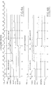
- Figure 4 illustrates various engine operating parameters during a transition from fractional operation with, in this case, four activated cylinders, to maximum operation with eight activated cylinders, and vice versa.
- the line labelled "CID" shows the various engine cylinders in firing sequence. The leading edge of each pulse corresponds to about 10° BTDC (before top dead centre) on the compression stroke for the numbered cylinder.
- the line labelled "VS#5" shows the condition of the cylinder control valve corresponding, in this example, to cylinder number five.
- the cylinder chosen for initiation of any particular activation or deactivation sequence may be selected so as to minimise the number of engine cycles which occur prior to completion of the change in the number of active cylinders.
- the line labelled "IN-EX#5 shows the operational condition of the intake and exhaust valves for cylinder five.
- the line labelled “NVS OFF” shows the number of cylinder control valves 16 which have been de-energised, so as to activate the valves associated with the various cylinders.
- Line “NCYL” indicates the number of activated, or firing, cylinders.
- the line labelled “MODE8FLG” shows whether the engine is operating according to a four or eight cylinder firing frequency.
- the line labelled "INJ#5 indicates operation of the injector for cylinder five.
- an eight cylinder engine runs at either maximum operation with all eight cylinders activated, or minimum operation with four cylinders.
- the cylinders which may be deactivated are numbers 5, 8, 3, and 2. As noted above, this range of deactivation is only an example, and the present invention may be employed to activate and deactivate any number of cylinders within an engine.
- a command is given by processor 10A to activate additional cylinders of the engine, beginning with cylinder five.
- time t1 coincides with the CID pulse for cylinder three.
- the command is given at time t1 because as cylinder three approaches top dead centre on its compression stroke, cylinder five, which is exactly 360° out of phase with cylinder three, has started its intake events, including the intake stroke. Accordingly, the CID line allows processor 10A to determine when the various cylinders are undergoing their intake events. In this case, however, the exhaust and intake valves for cylinder five are deactivated at time t1, as shown in the IN-EX#5 line.
- line VS#5 shows that the cylinder control valve 16 for cylinder number five is turned off so that pins 30 within followers 20 for cylinder five will be driven into their respective rocker arms 22 by springs 32, with the result that by time t5, both the intake and exhaust valves associated with cylinder five will be activated, as shown in the IN-EX#5 line.
- the reactivation begins during the time an intake event would occur if the intake valve were operational; the reactivation is completed by a time not later than the beginning of the next exhaust event.
- the NVS OFF line shows that at time t1 one additional cylinder control valve, which in this example comprises the control valve for cylinder five, is on. Controller 10 reactivates successive cylinders so that each reactivated cylinder will draw a fresh, uncontaminated charge during its first intake stroke. This occurs because the exhaust valve for each cylinder is always deactivated and reactivated before the intake valve deactivations and reactivations. Exhaust emission control is aided because the cylinder first exhausts the burnt gases and then draws in a fresh charge, including fuel at the desired air/fuel ratio.
- the NCYL line shows that the number of activated cylinders begins increasing to eight by time t5. Because the cylinders are reactivated at a rate which matches their firing frequency, the engine is actually operating at an eight cylinder firing frequency at time t5, as shown in the MODE8FLG line, which has a step increase at time t5.
- the injector for cylinder 5 is enabled; this enablement allows the injector to fire in a short period of time prior to the following CID pulse for cylinder 3. In this manner, fuel will be available for induction into cylinder 5 when the intake and exhaust valves have been reactivated at time t5. Note that because the reactivation of the injector occurs prior to the intake event following the first reactivated exhaust event, the cylinder is able to fire normally, and this means that a chemically correct exhaust mixture is discharged into the exhaust system. This is important because if the cylinder were to discharge only air, the exhaust after treatment system could be upset.
- the eight to four cylinder transition illustrated in Figure 4B shows that the transition from maximum operation with eight activated cylinders to fractional operation with, in this case, four activated cylinders, begins at time t1, with the command on the VS#5 line to turn on the cylinder control valve for cylinder five.
- the intake and exhaust valves for cylinder five are deactivated by time t5.
- the deactivation proceeds through the engine firing order and, as shown in the NVS ON line, the cylinder control valves for cylinders eight, three, and two are turned on at times t2, t3, and t4, respectively.
- the valves for cylinder 5 are on, and the NCYL line shows that the number of activated cylinders begins decreasing to four by time t5.
- the MODE8FLG line shows that the engine has reached a four cylinder firing frequency by time t5.
- the injector for cylinder five is disabled.
- the injectors associated with the other cylinders to be deactivated are disabled in firing order sequence such that their disablement occurs by the time the intake event has been completed. Note however, that because the deactivated cylinders draw one final fresh charge, including air and fuel, the cylinder is able to fire with a chemically correct mixture, as determined by controller 10. This means that the exhaust gases which are discharged when the cylinder is reactivated will have the composition desired for after treatment.
Landscapes
- Engineering & Computer Science (AREA)
- Mechanical Engineering (AREA)
- General Engineering & Computer Science (AREA)
- Chemical & Material Sciences (AREA)
- Combustion & Propulsion (AREA)
- Output Control And Ontrol Of Special Type Engine (AREA)
- Valve Device For Special Equipments (AREA)
Applications Claiming Priority (2)
| Application Number | Priority Date | Filing Date | Title |
|---|---|---|---|
| US172350 | 1980-07-25 | ||
| US08/172,350 US5408966A (en) | 1993-12-23 | 1993-12-23 | System and method for synchronously activating cylinders within a variable displacement engine |
Publications (2)
| Publication Number | Publication Date |
|---|---|
| EP0659993A2 true EP0659993A2 (de) | 1995-06-28 |
| EP0659993A3 EP0659993A3 (de) | 1996-07-17 |
Family
ID=22627342
Family Applications (1)
| Application Number | Title | Priority Date | Filing Date |
|---|---|---|---|
| EP94308876A Withdrawn EP0659993A3 (de) | 1993-12-23 | 1994-11-30 | System und Verfahren zur Steuerung einer Brennkraftmaschine. |
Country Status (3)
| Country | Link |
|---|---|
| US (1) | US5408966A (de) |
| EP (1) | EP0659993A3 (de) |
| JP (1) | JPH07208221A (de) |
Cited By (5)
| Publication number | Priority date | Publication date | Assignee | Title |
|---|---|---|---|---|
| DE19628024A1 (de) * | 1996-07-11 | 1998-01-15 | Siemens Ag | Brennkraftmaschine |
| DE19632651A1 (de) * | 1996-08-13 | 1998-02-19 | Siemens Ag | Steuereinrichtung zum Steuern eines Aktors |
| FR2869643A1 (fr) * | 2004-04-29 | 2005-11-04 | Peugeot Citroen Automobiles Sa | Procede de commande du fonctionnement d'un cylindre de moteur a combustion interne |
| DE102005010290A1 (de) * | 2005-03-02 | 2006-09-21 | Volkswagen Ag | Verfahren und Vorrichtung zur Ventilsteuerung beim Startvorgang eines Verbrennungsmotors |
| DE19546549C5 (de) * | 1995-12-13 | 2006-11-16 | Daimlerchrysler Ag | Verfahren zum Ab- und Zuschalten einzelner Zylinder |
Families Citing this family (58)
| Publication number | Priority date | Publication date | Assignee | Title |
|---|---|---|---|---|
| US5653102A (en) * | 1995-08-31 | 1997-08-05 | Ford Global Technologies, Inc. | Air/fuel control system with catalytic converter monitoring for a variable displacement engine |
| US5642703A (en) * | 1995-10-16 | 1997-07-01 | Ford Motor Company | Internal combustion engine with intake and exhaust camshaft phase shifting for cylinder deactivation |
| IT1280984B1 (it) * | 1995-10-18 | 1998-02-11 | Fiat Auto Spa | Sistema per il controllo dell'alimentazione di un motore alternativo a combustione interna. |
| US5769041A (en) * | 1996-04-26 | 1998-06-23 | Yamaha Hatsudoki Kabushiki Kaisha | Two cycle fuel injection engine |
| JPH1089108A (ja) * | 1996-09-20 | 1998-04-07 | Yamaha Motor Co Ltd | 筒内噴射式2サイクルエンジンの運転制御装置 |
| US5721375A (en) * | 1996-11-13 | 1998-02-24 | Ford Global Technologies, Inc. | Method and apparatus for monitoring a valve deactivator on a variable displacement engine |
| US5778858A (en) * | 1996-12-17 | 1998-07-14 | Dudley Frank | Fuel injection split engine |
| US5975052A (en) * | 1998-01-26 | 1999-11-02 | Moyer; David F. | Fuel efficient valve control |
| US6174291B1 (en) | 1998-03-09 | 2001-01-16 | Spectrascience, Inc. | Optical biopsy system and methods for tissue diagnosis |
| US5950582A (en) * | 1998-06-08 | 1999-09-14 | Ford Global Technologies, Inc. | Internal combustion engine with variable camshaft timing and intake valve masking |
| US5960755A (en) * | 1998-06-09 | 1999-10-05 | Ford Global Technologies, Inc. | Internal combustion engine with variable camshaft timing and variable duration exhaust event |
| US5957096A (en) * | 1998-06-09 | 1999-09-28 | Ford Global Technologies, Inc. | Internal combustion engine with variable camshaft timing, charge motion control valve, and variable air/fuel ratio |
| US6246951B1 (en) | 1999-05-06 | 2001-06-12 | Ford Global Technologies, Inc. | Torque based driver demand interpretation with barometric pressure compensation |
| US6434466B1 (en) | 1999-05-06 | 2002-08-13 | Ford Global Technologies, Inc. | System and method for determining engine torque for controlling a powertrain |
| US6119063A (en) * | 1999-05-10 | 2000-09-12 | Ford Global Technologies, Inc. | System and method for smooth transitions between engine mode controllers |
| JP3733786B2 (ja) * | 1999-05-21 | 2006-01-11 | トヨタ自動車株式会社 | 電磁駆動弁を有する内燃機関 |
| US6220987B1 (en) | 1999-05-26 | 2001-04-24 | Ford Global Technologies, Inc. | Automatic transmission ratio change schedules based on desired powertrain output |
| US6425373B1 (en) | 1999-08-04 | 2002-07-30 | Ford Global Technologies, Inc. | System and method for determining engine control parameters based on engine torque |
| US6279531B1 (en) | 1999-08-09 | 2001-08-28 | Ford Global Technologies, Inc. | System and method for controlling engine torque |
| US6691807B1 (en) * | 2000-04-11 | 2004-02-17 | Ford Global Technologies Llc | Hybrid electric vehicle with variable displacement engine |
| US6499449B2 (en) | 2001-01-25 | 2002-12-31 | Ford Global Technologies, Inc. | Method and system for operating variable displacement internal combustion engine |
| US6976307B2 (en) * | 2001-08-23 | 2005-12-20 | General Motors Corporation | Accelerated vehicle development process |
| US6772724B2 (en) * | 2002-03-12 | 2004-08-10 | Ford Global Technologies, Llc | Variable displacement engine starting control |
| US6647947B2 (en) * | 2002-03-12 | 2003-11-18 | Ford Global Technologies, Llc | Strategy and control system for deactivation and reactivation of cylinders of a variable displacement engine |
| US6715289B2 (en) * | 2002-04-08 | 2004-04-06 | General Motors Corporation | Turbo-on-demand engine with cylinder deactivation |
| US6915781B2 (en) | 2002-05-17 | 2005-07-12 | General Motors Corporation | Engine control system with throttle preload during cylinder deactivation |
| US6655353B1 (en) | 2002-05-17 | 2003-12-02 | General Motors Corporation | Cylinder deactivation engine control system with torque matching |
| US6769403B2 (en) | 2002-05-17 | 2004-08-03 | General Motors Corporation | Spark retard control during cylinder transitions in a displacement on demand engine |
| JP2005195059A (ja) * | 2004-01-05 | 2005-07-21 | Bando Chem Ind Ltd | オートテンショナの制御装置 |
| FR2869644B1 (fr) * | 2004-04-29 | 2006-06-16 | Peugeot Citroen Automobiles Sa | Procede de commande du fonctionnement d'un groupe de cylindres d'un moteur a combustion interne |
| JP4207965B2 (ja) * | 2006-02-10 | 2009-01-14 | トヨタ自動車株式会社 | 内燃機関の制御装置 |
| KR100743388B1 (ko) * | 2006-03-09 | 2007-07-27 | (주) 티피씨 메카트로닉스 | 매니폴드형 전자밸브의 제어 절환장치 |
| US7325521B1 (en) | 2006-08-02 | 2008-02-05 | Ford Global Technologies, Llc | System and method for improved cam retard |
| US8701628B2 (en) | 2008-07-11 | 2014-04-22 | Tula Technology, Inc. | Internal combustion engine control for improved fuel efficiency |
| US8131447B2 (en) * | 2008-07-11 | 2012-03-06 | Tula Technology, Inc. | Internal combustion engine control for improved fuel efficiency |
| US8616181B2 (en) | 2008-07-11 | 2013-12-31 | Tula Technology, Inc. | Internal combustion engine control for improved fuel efficiency |
| US7577511B1 (en) | 2008-07-11 | 2009-08-18 | Tula Technology, Inc. | Internal combustion engine control for improved fuel efficiency |
| US8336521B2 (en) * | 2008-07-11 | 2012-12-25 | Tula Technology, Inc. | Internal combustion engine control for improved fuel efficiency |
| US9020735B2 (en) | 2008-07-11 | 2015-04-28 | Tula Technology, Inc. | Skip fire internal combustion engine control |
| US7900509B2 (en) * | 2008-08-06 | 2011-03-08 | Ford Global Technologies, Llc | Methods for variable displacement engine diagnostics |
| US7757657B2 (en) * | 2008-09-11 | 2010-07-20 | Gm Global Technology Operations, Inc. | Dual active fuel management sequencing |
| US8150605B2 (en) * | 2009-02-17 | 2012-04-03 | Ford Global Technologies, Llc | Coordination of variable cam timing and variable displacement engine systems |
| US7835848B1 (en) * | 2009-05-01 | 2010-11-16 | Ford Global Technologies, Llc | Coordination of variable cam timing and variable displacement engine systems |
| US8511281B2 (en) | 2009-07-10 | 2013-08-20 | Tula Technology, Inc. | Skip fire engine control |
| WO2012075290A1 (en) | 2010-12-01 | 2012-06-07 | Tula Technology, Inc. | Skip fire internal combustion engine control |
| CN107131067B (zh) | 2011-10-17 | 2020-04-07 | 图拉技术公司 | 跳过点火发动机控制中的点火分数管理 |
| US9745905B2 (en) | 2011-10-17 | 2017-08-29 | Tula Technology, Inc. | Skip fire transition control |
| US8839766B2 (en) | 2012-03-30 | 2014-09-23 | Tula Technology, Inc. | Control of a partial cylinder deactivation engine |
| US9200587B2 (en) | 2012-04-27 | 2015-12-01 | Tula Technology, Inc. | Look-up table based skip fire engine control |
| US9291106B2 (en) | 2013-03-15 | 2016-03-22 | Tula Technology, Inc. | Cam phaser control |
| US9200575B2 (en) | 2013-03-15 | 2015-12-01 | Tula Technology, Inc. | Managing engine firing patterns and pattern transitions during skip fire engine operation |
| US10247121B2 (en) | 2014-03-13 | 2019-04-02 | Tula Technology, Inc. | Method and apparatus for determining optimum skip fire firing profile |
| US10100754B2 (en) | 2016-05-06 | 2018-10-16 | Tula Technology, Inc. | Dynamically varying an amount of slippage of a torque converter clutch provided between an engine and a transmission of a vehicle |
| US9739212B1 (en) | 2016-05-06 | 2017-08-22 | Tula Technology, Inc. | Method and apparatus for determining optimum skip fire firing profile with adjustments for ambient temperature |
| US10138860B2 (en) | 2016-02-17 | 2018-11-27 | Tula Technology, Inc. | Firing fraction transition control |
| US9777658B2 (en) | 2016-02-17 | 2017-10-03 | Tula Technology, Inc. | Skip fire transition control |
| US10344682B1 (en) | 2017-01-13 | 2019-07-09 | Andre H Vandenberg | Engine valve shaft with flow passages for intake and exhaust control |
| DE112021004484T5 (de) * | 2020-08-27 | 2023-10-19 | Cummins Inc. | Nachlademanagement für das auslassen von zylindern |
Family Cites Families (33)
| Publication number | Priority date | Publication date | Assignee | Title |
|---|---|---|---|---|
| US4040395A (en) * | 1973-11-05 | 1977-08-09 | Demetrescu Mihai C | Engine selectively utilizing hybrid thermodynamic combustion cycles |
| JPS52145630A (en) * | 1976-05-31 | 1977-12-03 | Nissan Motor Co Ltd | Fuel feed cylinder number controller |
| US4173209A (en) * | 1977-07-14 | 1979-11-06 | Jordan Edgar R | Engine control system and valve deactivator thereof |
| JPS564818Y2 (de) * | 1977-10-26 | 1981-02-02 | ||
| JPS54118918U (de) * | 1978-02-10 | 1979-08-20 | ||
| JPS55151131A (en) * | 1979-05-15 | 1980-11-25 | Nissan Motor Co Ltd | Apparatus for controlling number of cylinders to be supplied with fuel |
| US4391095A (en) * | 1981-07-02 | 1983-07-05 | Texaco Inc. | Internal combustion engine with exhaust filter rejuvenation |
| DE3129078A1 (de) * | 1981-07-23 | 1983-02-03 | Daimler-Benz Ag, 7000 Stuttgart | Verfahren zur aussetzregelung einer periodisch arbeitenden brennkraftmaschine |
| JPS5841232A (ja) * | 1981-09-02 | 1983-03-10 | Hitachi Ltd | 気筒数変換形燃料噴射ポンプの制御装置 |
| US4494502A (en) * | 1982-01-27 | 1985-01-22 | Mitsubishi Jidosha Kogyo Kabushiki Kaisha | Idling controller of variable displacement engine |
| JPS58200048A (ja) * | 1982-05-18 | 1983-11-21 | Fuji Heavy Ind Ltd | 燃料供給気筒数制御装置 |
| JPS5915648A (ja) * | 1982-07-16 | 1984-01-26 | Nissan Motor Co Ltd | 気筒数切換制御装置 |
| DE3313038A1 (de) * | 1983-04-12 | 1984-10-18 | Robert Bosch Gmbh, 7000 Stuttgart | Mehrzylinder-brennkraftmaschine mit abschaltbaren zylindergruppen |
| US4499870A (en) * | 1983-04-26 | 1985-02-19 | Nissan Motor Company, Limited | Multi-cylinder internal combustion engine |
| US4484551A (en) * | 1983-07-05 | 1984-11-27 | Ford Motor Company | Air-air/fuel control device |
| JPS6069344A (ja) * | 1983-08-31 | 1985-04-20 | Mazda Motor Corp | 気筒数制御エンジンのバランサ装置 |
| JPS60128915A (ja) * | 1983-12-17 | 1985-07-10 | Honda Motor Co Ltd | 多気筒内燃機関の弁作動休止装置 |
| GB8425926D0 (en) * | 1984-10-13 | 1984-11-21 | Lucas Ind Plc | Fuel control system |
| JPH0792003B2 (ja) * | 1984-12-28 | 1995-10-09 | トヨタ自動車株式会社 | 車両の加速スリップ制御装置 |
| JP2679970B2 (ja) * | 1985-10-21 | 1997-11-19 | 株式会社日立製作所 | アイドル回転速度制御装置 |
| DE3637958C1 (de) * | 1986-11-07 | 1987-07-16 | Audi Ag | Vorrichtung an einem Kraftfahrzeug |
| DE3923757A1 (de) * | 1988-07-20 | 1990-01-25 | Mitsubishi Electric Corp | Kraftstoffregler fuer brennkraftmaschinen |
| JP2507550B2 (ja) * | 1988-08-29 | 1996-06-12 | 三菱電機株式会社 | 燃料制御装置 |
| JPH02123212A (ja) * | 1988-10-31 | 1990-05-10 | Isuzu Motors Ltd | バルブ制御装置 |
| JPH0381542A (ja) * | 1989-08-24 | 1991-04-05 | Mazda Motor Corp | エンジンの制御装置 |
| JPH0392554A (ja) * | 1989-09-05 | 1991-04-17 | Nissan Motor Co Ltd | 車両用エンジン出力制御装置 |
| DE3940752A1 (de) * | 1989-12-09 | 1991-06-13 | Bosch Gmbh Robert | Verfahren zum steuern eines ottomotors ohne drosselklappe |
| US5042444A (en) * | 1990-03-07 | 1991-08-27 | Cummins Engine Company, Inc. | Device and method for altering the acoustic signature of an internal combustion engine |
| US5113823A (en) * | 1990-04-06 | 1992-05-19 | Nissan Motor Company, Limited | Throttle valve control apparatus for use with internal combustion engine |
| JPH0441944A (ja) * | 1990-06-05 | 1992-02-12 | Japan Electron Control Syst Co Ltd | 内燃機関の出力制御装置 |
| US5119781A (en) * | 1991-02-28 | 1992-06-09 | General Motors Corporation | Control of engine fuel injection during transitional periods associated with deceleration fuel cut-off |
| JPH0586956A (ja) * | 1991-09-27 | 1993-04-06 | Mitsubishi Electric Corp | 内燃機関の失火検出装置 |
| US5190013A (en) * | 1992-01-10 | 1993-03-02 | Siemens Automotive L.P. | Engine intake valve selective deactivation system and method |
-
1993
- 1993-12-23 US US08/172,350 patent/US5408966A/en not_active Expired - Fee Related
-
1994
- 1994-11-09 JP JP6275172A patent/JPH07208221A/ja active Pending
- 1994-11-30 EP EP94308876A patent/EP0659993A3/de not_active Withdrawn
Cited By (10)
| Publication number | Priority date | Publication date | Assignee | Title |
|---|---|---|---|---|
| DE19546549C5 (de) * | 1995-12-13 | 2006-11-16 | Daimlerchrysler Ag | Verfahren zum Ab- und Zuschalten einzelner Zylinder |
| DE19628024A1 (de) * | 1996-07-11 | 1998-01-15 | Siemens Ag | Brennkraftmaschine |
| DE19628024C2 (de) * | 1996-07-11 | 1999-04-01 | Siemens Ag | Brennkraftmaschine |
| DE19632651A1 (de) * | 1996-08-13 | 1998-02-19 | Siemens Ag | Steuereinrichtung zum Steuern eines Aktors |
| DE19632651C2 (de) * | 1996-08-13 | 1999-09-16 | Siemens Ag | Steuereinrichtung und Verfahren zum Steuern eines Aktors |
| FR2869643A1 (fr) * | 2004-04-29 | 2005-11-04 | Peugeot Citroen Automobiles Sa | Procede de commande du fonctionnement d'un cylindre de moteur a combustion interne |
| WO2005113963A3 (fr) * | 2004-04-29 | 2006-02-02 | Peugeot Citroen Automobiles Sa | Procede de commande du fonctionnement d'un cylindre de moteur a combustion interne |
| US7527032B2 (en) | 2004-04-29 | 2009-05-05 | Peugeot Citroen Automobiles Sa | Method for controlling the operation of a cylinder for an internal combustion engine |
| DE102005010290A1 (de) * | 2005-03-02 | 2006-09-21 | Volkswagen Ag | Verfahren und Vorrichtung zur Ventilsteuerung beim Startvorgang eines Verbrennungsmotors |
| DE102005010290B4 (de) * | 2005-03-02 | 2017-07-06 | Volkswagen Ag | Verfahren und Vorrichtung zur Ventilsteuerung beim Startvorgang eines Verbrennungsmotors |
Also Published As
| Publication number | Publication date |
|---|---|
| US5408966A (en) | 1995-04-25 |
| JPH07208221A (ja) | 1995-08-08 |
| EP0659993A3 (de) | 1996-07-17 |
Similar Documents
| Publication | Publication Date | Title |
|---|---|---|
| US5408966A (en) | System and method for synchronously activating cylinders within a variable displacement engine | |
| US6752121B2 (en) | Cylinder deactivation system timing control synchronization | |
| JP2954350B2 (ja) | 内燃機関の作動モードを制御する装置 | |
| US6823827B2 (en) | Control apparatus of internal combustion engine and method thereof | |
| US7231907B2 (en) | Variable incremental activation and deactivation of cylinders in a displacement on demand engine | |
| US11035313B2 (en) | System and method for engine poppet valve diagnostics | |
| US5992390A (en) | Fuel efficient hybrid internal combustion engine | |
| US20090048763A1 (en) | Control Apparatus and Control Method of an Internal Combustion Engine | |
| CN101278113B (zh) | 用于内燃机的控制设备和方法 | |
| US6553962B1 (en) | Exhaust valve deactivation and intake valve phasing to enable deceleration fuel shut off and engine braking | |
| US20050061283A1 (en) | Combustion-assisted engine start/stop operation with cylinder/valve deactivation | |
| JPH07208222A (ja) | 可変排気量内燃機関の遷移トルク出力を制御するシステム | |
| US7490001B2 (en) | Method for controlling the operation of a cylinder group for an internal combustion engine | |
| KR102604964B1 (ko) | 적어도 2개의 실린더를 위한 비활성화기들에 작동 가능하게 연결된 비활성화기 제어기를 구비한 시스템 및 실린더 비활성화를 위한 방법 | |
| JP3503277B2 (ja) | 多気筒エンジンの制御装置 | |
| US10107208B2 (en) | System and method to operate an engine | |
| US7527032B2 (en) | Method for controlling the operation of a cylinder for an internal combustion engine | |
| WO2007120398A1 (en) | Method and apparatus for controlling engine valve timing | |
| EP1342900A2 (de) | Abschaltsteuerung einer Brennkraftmachine | |
| US9523292B2 (en) | Valve control system for internal combustion engines and method of operation thereof | |
| JP2002227672A (ja) | 内燃機関の制御装置 | |
| US12123364B2 (en) | Control system and method for controlling operation of an internal combustion engine | |
| GB2585053A (en) | A controller and a method for controlling an internal combustion engine | |
| JPH09158749A (ja) | 内燃機関のバルブタイミング制御装置 | |
| JPH05223047A (ja) | 弁停止機構付き内燃機関の点火制御装置 |
Legal Events
| Date | Code | Title | Description |
|---|---|---|---|
| PUAI | Public reference made under article 153(3) epc to a published international application that has entered the european phase |
Free format text: ORIGINAL CODE: 0009012 |
|
| AK | Designated contracting states |
Kind code of ref document: A2 Designated state(s): DE FR GB |
|
| PUAL | Search report despatched |
Free format text: ORIGINAL CODE: 0009013 |
|
| AK | Designated contracting states |
Kind code of ref document: A3 Designated state(s): DE FR GB |
|
| 17P | Request for examination filed |
Effective date: 19970117 |
|
| STAA | Information on the status of an ep patent application or granted ep patent |
Free format text: STATUS: THE APPLICATION HAS BEEN WITHDRAWN |
|
| 18W | Application withdrawn |
Withdrawal date: 19970220 |