EP0661768A1 - Méthode d'échange thermique dans un dispositif de reformage - Google Patents
Méthode d'échange thermique dans un dispositif de reformage Download PDFInfo
- Publication number
- EP0661768A1 EP0661768A1 EP94309741A EP94309741A EP0661768A1 EP 0661768 A1 EP0661768 A1 EP 0661768A1 EP 94309741 A EP94309741 A EP 94309741A EP 94309741 A EP94309741 A EP 94309741A EP 0661768 A1 EP0661768 A1 EP 0661768A1
- Authority
- EP
- European Patent Office
- Prior art keywords
- flue gas
- catalyst tubes
- porous media
- reformer
- tubes
- Prior art date
- Legal status (The legal status is an assumption and is not a legal conclusion. Google has not performed a legal analysis and makes no representation as to the accuracy of the status listed.)
- Granted
Links
Images


Classifications
-
- H—ELECTRICITY
- H01—ELECTRIC ELEMENTS
- H01M—PROCESSES OR MEANS, e.g. BATTERIES, FOR THE DIRECT CONVERSION OF CHEMICAL ENERGY INTO ELECTRICAL ENERGY
- H01M8/00—Fuel cells; Manufacture thereof
- H01M8/06—Combination of fuel cells with means for production of reactants or for treatment of residues
- H01M8/0606—Combination of fuel cells with means for production of reactants or for treatment of residues with means for production of gaseous reactants
- H01M8/0612—Combination of fuel cells with means for production of reactants or for treatment of residues with means for production of gaseous reactants from carbon-containing material
- H01M8/0625—Combination of fuel cells with means for production of reactants or for treatment of residues with means for production of gaseous reactants from carbon-containing material in a modular combined reactor/fuel cell structure
- H01M8/0631—Reactor construction specially adapted for combination reactor/fuel cell
-
- B—PERFORMING OPERATIONS; TRANSPORTING
- B01—PHYSICAL OR CHEMICAL PROCESSES OR APPARATUS IN GENERAL
- B01J—CHEMICAL OR PHYSICAL PROCESSES, e.g. CATALYSIS OR COLLOID CHEMISTRY; THEIR RELEVANT APPARATUS
- B01J8/00—Chemical or physical processes in general, conducted in the presence of fluids and solid particles; Apparatus for such processes
- B01J8/02—Chemical or physical processes in general, conducted in the presence of fluids and solid particles; Apparatus for such processes with stationary particles, e.g. in fixed beds
- B01J8/06—Chemical or physical processes in general, conducted in the presence of fluids and solid particles; Apparatus for such processes with stationary particles, e.g. in fixed beds in tube reactors; the solid particles being arranged in tubes
- B01J8/067—Heating or cooling the reactor
-
- C—CHEMISTRY; METALLURGY
- C01—INORGANIC CHEMISTRY
- C01B—NON-METALLIC ELEMENTS; COMPOUNDS THEREOF; METALLOIDS OR COMPOUNDS THEREOF NOT COVERED BY SUBCLASS C01C
- C01B3/00—Hydrogen; Gaseous mixtures containing hydrogen; Separation of hydrogen from mixtures containing it; Purification of hydrogen; Reversible storage of hydrogen
- C01B3/02—Production of hydrogen; Production of gaseous mixtures containing hydrogen
- C01B3/32—Production of hydrogen; Production of gaseous mixtures containing hydrogen by reaction of gaseous or liquid organic compounds with gasifying agents, e.g. water, carbon dioxide or air
- C01B3/34—Production of hydrogen; Production of gaseous mixtures containing hydrogen by reaction of gaseous or liquid organic compounds with gasifying agents, e.g. water, carbon dioxide or air by reaction of hydrocarbons with gasifying agents
- C01B3/38—Production of hydrogen; Production of gaseous mixtures containing hydrogen by reaction of gaseous or liquid organic compounds with gasifying agents, e.g. water, carbon dioxide or air by reaction of hydrocarbons with gasifying agents using catalysts
- C01B3/384—Production of hydrogen; Production of gaseous mixtures containing hydrogen by reaction of gaseous or liquid organic compounds with gasifying agents, e.g. water, carbon dioxide or air by reaction of hydrocarbons with gasifying agents using catalysts with external heating of the catalyst
-
- B—PERFORMING OPERATIONS; TRANSPORTING
- B01—PHYSICAL OR CHEMICAL PROCESSES OR APPARATUS IN GENERAL
- B01J—CHEMICAL OR PHYSICAL PROCESSES, e.g. CATALYSIS OR COLLOID CHEMISTRY; THEIR RELEVANT APPARATUS
- B01J2208/00—Processes carried out in the presence of solid particles; Reactors therefor
- B01J2208/00008—Controlling the process
- B01J2208/00017—Controlling the temperature
- B01J2208/00106—Controlling the temperature by indirect heat exchange
- B01J2208/00168—Controlling the temperature by indirect heat exchange with heat exchange elements outside the bed of solid particles
- B01J2208/00212—Plates; Jackets; Cylinders
-
- C—CHEMISTRY; METALLURGY
- C01—INORGANIC CHEMISTRY
- C01B—NON-METALLIC ELEMENTS; COMPOUNDS THEREOF; METALLOIDS OR COMPOUNDS THEREOF NOT COVERED BY SUBCLASS C01C
- C01B2203/00—Integrated processes for the production of hydrogen or synthesis gas
- C01B2203/02—Processes for making hydrogen or synthesis gas
- C01B2203/0205—Processes for making hydrogen or synthesis gas containing a reforming step
- C01B2203/0227—Processes for making hydrogen or synthesis gas containing a reforming step containing a catalytic reforming step
- C01B2203/0233—Processes for making hydrogen or synthesis gas containing a reforming step containing a catalytic reforming step the reforming step being a steam reforming step
-
- C—CHEMISTRY; METALLURGY
- C01—INORGANIC CHEMISTRY
- C01B—NON-METALLIC ELEMENTS; COMPOUNDS THEREOF; METALLOIDS OR COMPOUNDS THEREOF NOT COVERED BY SUBCLASS C01C
- C01B2203/00—Integrated processes for the production of hydrogen or synthesis gas
- C01B2203/06—Integration with other chemical processes
- C01B2203/066—Integration with other chemical processes with fuel cells
-
- C—CHEMISTRY; METALLURGY
- C01—INORGANIC CHEMISTRY
- C01B—NON-METALLIC ELEMENTS; COMPOUNDS THEREOF; METALLOIDS OR COMPOUNDS THEREOF NOT COVERED BY SUBCLASS C01C
- C01B2203/00—Integrated processes for the production of hydrogen or synthesis gas
- C01B2203/08—Methods of heating or cooling
- C01B2203/0805—Methods of heating the process for making hydrogen or synthesis gas
-
- C—CHEMISTRY; METALLURGY
- C01—INORGANIC CHEMISTRY
- C01B—NON-METALLIC ELEMENTS; COMPOUNDS THEREOF; METALLOIDS OR COMPOUNDS THEREOF NOT COVERED BY SUBCLASS C01C
- C01B2203/00—Integrated processes for the production of hydrogen or synthesis gas
- C01B2203/08—Methods of heating or cooling
- C01B2203/0805—Methods of heating the process for making hydrogen or synthesis gas
- C01B2203/0811—Methods of heating the process for making hydrogen or synthesis gas by combustion of fuel
-
- C—CHEMISTRY; METALLURGY
- C01—INORGANIC CHEMISTRY
- C01B—NON-METALLIC ELEMENTS; COMPOUNDS THEREOF; METALLOIDS OR COMPOUNDS THEREOF NOT COVERED BY SUBCLASS C01C
- C01B2203/00—Integrated processes for the production of hydrogen or synthesis gas
- C01B2203/08—Methods of heating or cooling
- C01B2203/0805—Methods of heating the process for making hydrogen or synthesis gas
- C01B2203/0811—Methods of heating the process for making hydrogen or synthesis gas by combustion of fuel
- C01B2203/0822—Methods of heating the process for making hydrogen or synthesis gas by combustion of fuel the fuel containing hydrogen
-
- C—CHEMISTRY; METALLURGY
- C01—INORGANIC CHEMISTRY
- C01B—NON-METALLIC ELEMENTS; COMPOUNDS THEREOF; METALLOIDS OR COMPOUNDS THEREOF NOT COVERED BY SUBCLASS C01C
- C01B2203/00—Integrated processes for the production of hydrogen or synthesis gas
- C01B2203/08—Methods of heating or cooling
- C01B2203/0805—Methods of heating the process for making hydrogen or synthesis gas
- C01B2203/0811—Methods of heating the process for making hydrogen or synthesis gas by combustion of fuel
- C01B2203/0827—Methods of heating the process for making hydrogen or synthesis gas by combustion of fuel at least part of the fuel being a recycle stream
-
- C—CHEMISTRY; METALLURGY
- C01—INORGANIC CHEMISTRY
- C01B—NON-METALLIC ELEMENTS; COMPOUNDS THEREOF; METALLOIDS OR COMPOUNDS THEREOF NOT COVERED BY SUBCLASS C01C
- C01B2203/00—Integrated processes for the production of hydrogen or synthesis gas
- C01B2203/08—Methods of heating or cooling
- C01B2203/0805—Methods of heating the process for making hydrogen or synthesis gas
- C01B2203/0833—Heating by indirect heat exchange with hot fluids, other than combustion gases, product gases or non-combustive exothermic reaction product gases
-
- C—CHEMISTRY; METALLURGY
- C01—INORGANIC CHEMISTRY
- C01B—NON-METALLIC ELEMENTS; COMPOUNDS THEREOF; METALLOIDS OR COMPOUNDS THEREOF NOT COVERED BY SUBCLASS C01C
- C01B2203/00—Integrated processes for the production of hydrogen or synthesis gas
- C01B2203/08—Methods of heating or cooling
- C01B2203/0805—Methods of heating the process for making hydrogen or synthesis gas
- C01B2203/0838—Methods of heating the process for making hydrogen or synthesis gas by heat exchange with exothermic reactions, other than by combustion of fuel
- C01B2203/0844—Methods of heating the process for making hydrogen or synthesis gas by heat exchange with exothermic reactions, other than by combustion of fuel the non-combustive exothermic reaction being another reforming reaction as defined in groups C01B2203/02 - C01B2203/0294
-
- C—CHEMISTRY; METALLURGY
- C01—INORGANIC CHEMISTRY
- C01B—NON-METALLIC ELEMENTS; COMPOUNDS THEREOF; METALLOIDS OR COMPOUNDS THEREOF NOT COVERED BY SUBCLASS C01C
- C01B2203/00—Integrated processes for the production of hydrogen or synthesis gas
- C01B2203/08—Methods of heating or cooling
- C01B2203/0805—Methods of heating the process for making hydrogen or synthesis gas
- C01B2203/0866—Methods of heating the process for making hydrogen or synthesis gas by combination of different heating methods
-
- C—CHEMISTRY; METALLURGY
- C01—INORGANIC CHEMISTRY
- C01B—NON-METALLIC ELEMENTS; COMPOUNDS THEREOF; METALLOIDS OR COMPOUNDS THEREOF NOT COVERED BY SUBCLASS C01C
- C01B2203/00—Integrated processes for the production of hydrogen or synthesis gas
- C01B2203/10—Catalysts for performing the hydrogen forming reactions
- C01B2203/1041—Composition of the catalyst
-
- C—CHEMISTRY; METALLURGY
- C01—INORGANIC CHEMISTRY
- C01B—NON-METALLIC ELEMENTS; COMPOUNDS THEREOF; METALLOIDS OR COMPOUNDS THEREOF NOT COVERED BY SUBCLASS C01C
- C01B2203/00—Integrated processes for the production of hydrogen or synthesis gas
- C01B2203/12—Feeding the process for making hydrogen or synthesis gas
- C01B2203/1205—Composition of the feed
- C01B2203/1211—Organic compounds or organic mixtures used in the process for making hydrogen or synthesis gas
- C01B2203/1235—Hydrocarbons
- C01B2203/1241—Natural gas or methane
-
- C—CHEMISTRY; METALLURGY
- C01—INORGANIC CHEMISTRY
- C01B—NON-METALLIC ELEMENTS; COMPOUNDS THEREOF; METALLOIDS OR COMPOUNDS THEREOF NOT COVERED BY SUBCLASS C01C
- C01B2203/00—Integrated processes for the production of hydrogen or synthesis gas
- C01B2203/80—Aspect of integrated processes for the production of hydrogen or synthesis gas not covered by groups C01B2203/02 - C01B2203/1695
-
- Y—GENERAL TAGGING OF NEW TECHNOLOGICAL DEVELOPMENTS; GENERAL TAGGING OF CROSS-SECTIONAL TECHNOLOGIES SPANNING OVER SEVERAL SECTIONS OF THE IPC; TECHNICAL SUBJECTS COVERED BY FORMER USPC CROSS-REFERENCE ART COLLECTIONS [XRACs] AND DIGESTS
- Y02—TECHNOLOGIES OR APPLICATIONS FOR MITIGATION OR ADAPTATION AGAINST CLIMATE CHANGE
- Y02E—REDUCTION OF GREENHOUSE GAS [GHG] EMISSIONS, RELATED TO ENERGY GENERATION, TRANSMISSION OR DISTRIBUTION
- Y02E60/00—Enabling technologies; Technologies with a potential or indirect contribution to GHG emissions mitigation
- Y02E60/30—Hydrogen technology
- Y02E60/50—Fuel cells
-
- Y—GENERAL TAGGING OF NEW TECHNOLOGICAL DEVELOPMENTS; GENERAL TAGGING OF CROSS-SECTIONAL TECHNOLOGIES SPANNING OVER SEVERAL SECTIONS OF THE IPC; TECHNICAL SUBJECTS COVERED BY FORMER USPC CROSS-REFERENCE ART COLLECTIONS [XRACs] AND DIGESTS
- Y02—TECHNOLOGIES OR APPLICATIONS FOR MITIGATION OR ADAPTATION AGAINST CLIMATE CHANGE
- Y02P—CLIMATE CHANGE MITIGATION TECHNOLOGIES IN THE PRODUCTION OR PROCESSING OF GOODS
- Y02P20/00—Technologies relating to chemical industry
- Y02P20/10—Process efficiency
Definitions
- This invention relates to the enhancement of heat transfer in a multi-tubular reformer intended for the production of a reformed gas to be used in a fuel cell. More particularly, this invention, in the production of a reformed gas to be used in a fuel cell by using a multi-tubular reformer provided with a plurality of bayonet type double-wall catalyst tubes in a pressure vessel, relates to a method of exalting the utilization efficiency of the heat of the flue gas and ensuring uniform heating of the catalyst tubes by preventing the shell wall effect in thermal radiation and also preventing channelling of the flue gas in the shell side and a reformer employing the method mentioned above.
- the electric power generation with a fuel cell has been attracting attention as a method of electric power generation which enjoys high efficiency and low polution to the environment.
- the fuel cell operates on the principle that a direct current is extracted through an external circuit connected to an anode (hydrogen electrode) and a cathode (oxygen electrode) by feeding continuously hydrogen and oxygen respectively to the anode and the cathode with an electrolyte disposed between the two electrodes.
- the fuel cell is known in various types such as the alkali type (AFC), the phosphoric acid type (PAFC), and the molten carbonate type (MCFC), which depend on the kind of electrolyte to be used. These types are alike in feeding hydrogen (pure hydrogen or crude hydrogen) to the anode but are unlike in tolerating or not tolerating carbon dioxide or carbon monoxide in the hydrogen gas.
- the alkali type does not tolerate carbon dioxide or carbon monoxide in the hydrogen gas because carbon dioxide impairs the function of potassium hydroxide as an electrolyte and carbon monoxide poisons platinum being used as a catalyst and they both go to degrade the performance of the fuel cell.
- this type is at a disadvantage in necessitating use of substantially pure hydrogen as a fuel gas.
- the phosphoric acid type tolerates carbon dioxide but does not tolerate carbon monoxide because the latter poisons platinum being used as a catalyst.
- this type permits use of crude hydrogen on the condition that the carbon monoxide in the crude hydrogen be caused to react with steam in a carbon monoxide converter and converted into carbon dioxide and hydrogen.
- the molten carbonate type does not use a platinum catalyst and, therefore, tolerates both carbon dioxide and carbon monoxide in the hydrogen gas and, moreover, enjoys the advantage that the carbon monoxide reacts with the water generated at the anode to generate hydrogen which can be utilized as the fuel. Since the molten carbonate type has many other economic merits, it offers a promising prospect as an alternative to the thermal electric power generation of the medium to small scale.
- the fuel cell is known in the solid electrolyte type (SOFC), the polymer type (PFC) and so forth. Though these types have characteristics of their own, they are alike those mentioned above in feeding hydrogen to the anode.
- the crude hydrogen which is fed to the anode in the phosphoric acid type or the molten carbonate type fuel cell is generally produced by using hydrocarbon, such as natural gas (having methane as a main component) as a raw material and causing it to react with steam. This reaction is thought to proceed as represented by the following formula (1) or (2).
- the reaction is endothermic in nature and is generally carried out in the presence of a catalyst at a temperature in the range of from 600°C to 1000°C.
- the reformer is an apparatus to be used for implementing this reaction. It is generally so constructed as to pass the feed gas (natural gas and steam) through reaction tubes loaded with a catalyst and heat externally the reaction tubes by means of a burner or a hot fluid produced by catalytic combustion.
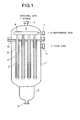
- Fig. 1 Atypical structure of the reformer of this type is illustrated schematically in Fig. 1.
- natural gas and steam as raw materials are introduced into a pressure vessel 1 via a feed gas inlet 2 disposed at one end (the top part in the diagram) of the pressure vessel and caused to flow through the clearances between inner tubes 3 and outer tubes 4 which jointly constitute bayonet type double-wall catalyst tubes.
- feed gas inlet 2 disposed at one end (the top part in the diagram) of the pressure vessel and caused to flow through the clearances between inner tubes 3 and outer tubes 4 which jointly constitute bayonet type double-wall catalyst tubes.
- These clearances are loaded with a reforming catalyst 5. While the feed gas is flowing through the catalyst layer, the natural gas and the steam react with each other to produce a hydrogencontaining reformed gas.
- the produced reformed gas is advanced inside the inner tubes 3 and fed through a manifold 6 to the fuel cell (not shown) via a reformed gas outlet 7.
- the pressure vessel 1 is provided at the other end (the bottom part in the diagram) with a flue gas feed part, which comprises a flue gas feed chamber 8 and a flue gas inlet 9 as illustrated in Fig. 1, for example.
- the flue gas is made to flow along the outer side (the shell side) of the outer tubes 4 and meanwhile heats the catalyst 5 externally and then is discharged through a flue gas outlet 11.
- the inner tubes 3 are supported by the manifold 6 and the outer tubes 4 are supported by a tube sheet 12.
- the heat necessary for the reforming reaction is supplied by the flue gas.
- the flue gas at an elevated temperature (1000°C to 1500°C) is made to flow in the shell side of the interior of the pressure vessel and meanwhile heat externally the outer tubes of the bayonet type catalyst tubes. Since the efficiency of heat transfer between the flue gas and the catalyst tubes generally is not very high, various measures have been adopted to date for enhancing the efficiency of heat transfer. For example, the practice of arranging sleeves, orifice baffles, or wire nets near the shell sides in the basal parts of the catalyst tubes (the parts near to the tube sheet and far from the flue gas inlet part) has been made.
- the number of catalyst tubes falls into the range of from 30 to 60.
- the reformer is likely to have uneven operating temperatures among the catalyst tubes.
- the differences in the operating temperature frequently reach as much as ⁇ 100°C in conventional reformers.
- the catalyst tubes of higher temperatures suffer from lowered life span and sintering of the reforming catalyst owing to overheating and those of lower temperatures suffer from impaired efficiency of electric power generation owing to a lowered conversion of the raw materials.
- the following three causes are conceivable for the uneven heating of the catalyst tubes.
- This invention in a multi-tubular reformer provided with a plurality of bayonet type double-wall catalyst tubes in a pressure vessel, enhances the transfer of heat between a flue gas and the catalyst tubes and, at the same time, represses the generation of uneven operating temperatures among the plurality of catalyst tubes and consequently solves the aforementioned problems by arranging a porous medium composed of ceramic foams in a shell side flue gas inlet part inside the reformer and causing the porous medium to envelope the leading end parts of the catalyst tubes.
- the porous media arranged in the shell side flue gas inlet part in the reformer are heated on contact with the hot flue gas flowing in the shell side and made to play the role of accumulating the thermal energy of the hot flue gas and consequently discharging the accumulated thermal energy toward the catalyst tubes. Since the fuel cell reformer which is aimed at a compact structure necessitates a high heat flux, radiant heat transfer is desired to predominate in the high-temperature zone in which the temperature of the flue gas exceeds 1000°C.
- the thermal radiation emissivity of a gaseous substance is extremely small as compared with that of a solid substance, the radiant heat transfer from a gaseous substance necessitates a large gas volume or a large shell side volume and, therefore, cannot be utilized for the fuel cell reformer aimed at a compact structure.
- the porous media offer a large heat-transfer area (contact area) and quickly accumulate the thermal energy of the flue gas.
- the porous media which have been heated radiate the accumulated thermal energy toward the walls of the outer tubes of the catalyst tubes and consequently serve to heat the catalyst tubes.
- the transfer of heat from the flue gas to the walls of the outer tubes is made by convective transfer and radiant transfer from the flue gas itself (which is not very effective in a compact structure).
- the transfer of heat from the flue gas to the walls of the outer tubes is attained by the combination of the convective transfer from the flue gas mentioned above with the radiant transfer from the porous media to the walls of the outer tubes. Since the thermal radiation emissivity of the porous media is large as compared with that of the flue gas, the heat transfer efficiency is notably improved for a specified shell side volume.
- the heat transfer enhancing means heretofore provided in the shell side is attached to the outer walls of the outer tubes of the catalyst tubes or connected to the tube sheet supporting the outer tubes and is required from reason of structure to be made of a metallic material.
- the porous media composed of ceramic foams offer much higher heat resistance than that of a metallic material and are usable at such sites of elevated temperatures as the leading end parts of the catalyst tubes.
- the fact that the porous media are arranged in the shell side also contributes to ensuring uniform heating of the catalyst tubes. Specifically, since the individual catalyst tubes are enveloped with the porous media, they are no longer exposed directly to the radiant heat from the shell wall orfrom the other catalyst tubes, and the individual catalyst tubes no longer affect each other in terms of the radiant heat transfer. This fact means that the wall effect and the shape factor otherwise involved in the radiant heat transfer are eliminated.
- porous media further confer suitable pressure drop on the flue gas flow path in the shell side extending from the flue gas inlet to the flue gas outlet nozzle part and, as a result, repress the channelling of the flue gas.
- the porous media so as to exert the greater part (not less than 80%) of the pressure drop on the section ranging from the flue gas inlet zone up to the zone seating the group of catalyst tubes, the flow of the flue gas, if complicated with swirl or vortex in the vicinity of the flue gas inlet zone, is rectified and deprived substantially of uneven pressure distribution and velocity distribution in the radial direction en route to the zone seating the group of catalyst tubes.
- the degree of uneveness of the flow of the flue gas in the downstream side can be expected to be diminished to a great extent.
- the first and the second causes mentioned above, therefore, are eliminated.
- the problem of uneven heating of the individual catalyst tubes substantially ceases to exist when the third cause, i.e.
- the porous media are of a heat-accumulating nature as mentioned above, their use brings about an effect of stably maintaining the temperature conditions of the reforming reaction inside the catalyst tubes.
- the porous media to be used for the present invention are required to have open cells and a large void ratio to allow easy passage of the flue gas. For the sake of offering a large heat-transfer area for the flow of the flue gas, they are desired to have a large specific surface area.
- the porous media which fulfill these conditions are represented by ceramic foams containing open cells at a ratio in the approximate range of from 4 to 40, preferably 6 to 13, cells per 25 mm.
- the ceramic foams of this kind are known to have been adopted for the filtration of molten metal and they can be formed in various shapes. When they are formed in the shape of blocks conforming to the cross-sectional shape of the catalyst tubes and enabled to accommodate the catalyst tubes snugly therein, the efficiency of the arranging work is exalted.
- the porous media to be arranged in the upstream side of the flue gas are destined to be heated up to the temperature of the flue gas and, therefore, are required to offer high heat resistance (even to above 1500°C).
- ceramic substances offer high heat resistance as compared with metallic substances.
- the ceramic substances of the mullite type, alumina type, zirconia type, or silicon carbide type have notably high heat resistance and, therefore, are fit for arrangement in the flue gas inlet part in the interior of the pressure vessel.
- the mere possession of a high melting point does not suffice. It is equally important for the sake of resistance to thermal shock that the thermal expansion coefficient be small and the thermal conductivity be large.
- the porous media are intended to envelope the leading end parts of the catalyst tubes and supply the heat necessary for the reforming reaction in the catalyst tubes, they give a temperature gradient such that the temperature gradually decreases in the direction of the downstream of the flue gas in the section ranging from the leading ends of the catalyst tubes to the zone of the flue gas outlet.
- the porous media which are arranged in the downstream side and the upstream side of the flue gas may be made of unlike materials because those in the downstream side are not always required to offer very high heat resistance.
- Fig. 2 illustrates a preferred embodiment of this invention.
- This embodiment has an apparatus of Fig. 1 arranged with porous media 13 and 14 made of a ceramic foam containing open cells to such an extent as to envelope catalyst tubes up to about two thirds of the length of catalyst tube from the leading end side.
- the porous media 13 are formed of a material having higher heat resistance than the material of the porous media 14.
- These porous media composed of ceramic foams are so formed as to accommodate the catalyst tubes snugly therein.
- the pressure vessel 2 may be attained by first setting in the bottom part of the interior of the pressure vessel a lump of porous media shaped in conformity with the shape of the bottom part of the pressure vessel, then arranging porous media so as to form holes for accommodating the catalyst tubes therein, and thereafter inserting the outer tubes of the catalyst tubes into the holes. Otherwise, it may be accomplished by first setting the outer tubes in position and then arranging porous media so as to fill the space remaining inside the pressure vessel after the setting of the outer tubes.
- Fig. 3 illustrates another preferred embodiment of this invention.
- This embodiment has an apparatus of Fig. 1 arranged with porous media 13 of ceramic foams containing open cells to such an extent as to envelope catalyst tubes up to about one third of the length of catalyst tube from the leading end side and, on the adjoining downstream side of the flue gas, with demister nets 15 to such an extent as to envelope catalyst tubes in a length of about one third of the central part of catalyst tube.
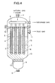
- Fig. 4 illustrates yet another preferred embodiment of this invention.
- This embodiment has the inner tubes of the catalyst tubes in an apparatus of Fig. 3 arranged with porous media 16 of ceramic foams containing open cells.
- porous media 16 of ceramic foams containing open cells In this structure, the transfer of heat between the hot reformed gas passing inside the inner tubes and the cold feed stock gas passing inside the catalyst layer is enhanced and the effective utilization of heat is ensured.
- the porous media of a ceramic material have a very scanty activity to catalyze the Boudouard's reaction and allow the S/C ratio to be lowered to a level of about 2.5 and, therefore, lower the stream consumption and facilitate to exalt the efficiency of electric power generation.
- the temperature at the inlet to the reformer was 434°C
- the temperature in the bottom parts of the catalyst tubes was 800°C
- the pressure in the bottom parts of the catalyst tubes was 2.4 kg/cm 2 G
- the temperature at the outlet of the reformer was 600°C.
- the composition of the reformed gas was as follows.
- the average heat flux (based on the outer surface area of the catalyst tubes) found at this time was 61000 Kcal/m 2 H.
- FIG. 4 An apparatus as illustrated in Fig. 4 and having a larger size was used for reforming natural gas.
- the apparatus incorporated 30 bayonet type catalyst tubes each consisting of an inner tube 165.2 mm in outside diameter and an outer tube 216.3 mm in outside diameter.
- a reforming catalyst (produced by Toyo CCI K.K. and marketed under brand of "FCR-4") was loaded in a height of 3000 mm.
- Porous media of a mullite type ceramic foam of a nominal size #13 (11 cells/25 mm) were used.
- Demister nets 15 made of stainless steel (SUS 310S) and having a void ratio of 99% and a density of 80 kg/m 3 were used.
- Porous media 16 of a mullite type ceramic foam of a nominal size #6 (4 to 9 cells/25 mm) were used in a height of 3000 mm inside the inner tubes.
- the natural gas had the following composition.
- the temperature at the inlet to the reformer was 450°C
- the temperature in the bottom parts of the catalyst tubes was 775°C on the average
- the pressure in the bottom parts of the catalyst tubes was 0.3 kg/cm 2 G
- the temperature at the outlet of the reformer was 550°C.
- the composition of the reformed gas was as follows.
- the average heat flux (based on the outer surface area of the catalyst tubes) found at this time was 55000 Kcal/m 2 H.
- the temperatures at the outlet parts of the catalyst layers of the 30 catalyst tubes were in the range of 775 ⁇ 30°C, indicating that the uneveness of temperature was +30°C.
- the pressure drop through from the flue gas inlet part to the outlet part was 400 mm H 2 0, of which the pressure drop through the ceramic foam part and the demister net part was about 350 mm H 2 0.
- the transfer of heat from the flue gas to the catalyst tubes is enhanced because the porous media accumulate the heat from the flue gas and radiate the accumulated heat in the direction of the walls of the outer tubes.
Landscapes
- Chemical & Material Sciences (AREA)
- Chemical Kinetics & Catalysis (AREA)
- Organic Chemistry (AREA)
- Engineering & Computer Science (AREA)
- Electrochemistry (AREA)
- Manufacturing & Machinery (AREA)
- Sustainable Development (AREA)
- Sustainable Energy (AREA)
- Life Sciences & Earth Sciences (AREA)
- General Chemical & Material Sciences (AREA)
- Health & Medical Sciences (AREA)
- General Health & Medical Sciences (AREA)
- Combustion & Propulsion (AREA)
- Inorganic Chemistry (AREA)
- Fuel Cell (AREA)
- Hydrogen, Water And Hydrids (AREA)
Applications Claiming Priority (4)
| Application Number | Priority Date | Filing Date | Title |
|---|---|---|---|
| JP334675/93 | 1993-12-28 | ||
| JP33467593 | 1993-12-28 | ||
| JP274790/94 | 1994-11-09 | ||
| JP27479094A JP3442167B2 (ja) | 1993-12-28 | 1994-11-09 | 改質器における伝熱方法 |
Publications (2)
| Publication Number | Publication Date |
|---|---|
| EP0661768A1 true EP0661768A1 (fr) | 1995-07-05 |
| EP0661768B1 EP0661768B1 (fr) | 1997-10-01 |
Family
ID=26551197
Family Applications (1)
| Application Number | Title | Priority Date | Filing Date |
|---|---|---|---|
| EP94309741A Expired - Lifetime EP0661768B1 (fr) | 1993-12-28 | 1994-12-23 | Méthode d'échange thermique dans un dispositif de reformage |
Country Status (4)
| Country | Link |
|---|---|
| US (1) | US5876469A (fr) |
| EP (1) | EP0661768B1 (fr) |
| JP (1) | JP3442167B2 (fr) |
| DE (1) | DE69405970D1 (fr) |
Cited By (4)
| Publication number | Priority date | Publication date | Assignee | Title |
|---|---|---|---|---|
| US6630423B2 (en) * | 2001-03-30 | 2003-10-07 | Siemens Westinghouse Power Corporation | Graded metal catalytic tubes |
| EP2800189A4 (fr) * | 2011-12-30 | 2015-09-23 | Doosan Heavy Ind & Constr | Pré-reformeur du type à échange de chaleur |
| RU2615768C1 (ru) * | 2016-05-27 | 2017-04-11 | Федеральное государственное бюджетное образовательное учреждение высшего образования "Ивановский государственный химико-технологический университет" (ИГХТУ) | Реактор для каталитической паровой и пароуглекислотной конверсии углеводородов |
| CN112705149A (zh) * | 2019-10-25 | 2021-04-27 | 中国石油化工股份有限公司 | 一种内衬石英反应器 |
Families Citing this family (32)
| Publication number | Priority date | Publication date | Assignee | Title |
|---|---|---|---|---|
| US7066973B1 (en) | 1996-08-26 | 2006-06-27 | Nuvera Fuel Cells | Integrated reformer and shift reactor |
| US5943859A (en) * | 1997-09-18 | 1999-08-31 | Isuzu Ceramics Research Institute Co., Ltd. | Natural gas reforming apparatus, oxygen eliminating apparatus provided in the same apparatus, and natural gas reforming apparatus-carrying gas engine |
| US6641625B1 (en) | 1999-05-03 | 2003-11-04 | Nuvera Fuel Cells, Inc. | Integrated hydrocarbon reforming system and controls |
| US6986797B1 (en) | 1999-05-03 | 2006-01-17 | Nuvera Fuel Cells Inc. | Auxiliary reactor for a hydrocarbon reforming system |
| US6458478B1 (en) * | 2000-09-08 | 2002-10-01 | Chi S. Wang | Thermoelectric reformer fuel cell process and system |
| DE10203022B4 (de) * | 2002-01-26 | 2008-02-07 | Forschungszentrum Jülich GmbH | Reaktor mit siebförmigen Körpern und Verfahren für den Reaktorbetrieb |
| JP2006502938A (ja) | 2002-06-13 | 2006-01-26 | ヌヴェラ フューエル セルズ インコーポレイテッド | 優先的酸化反応装置の温度調整 |
| JP4477432B2 (ja) | 2004-06-29 | 2010-06-09 | 東洋エンジニアリング株式会社 | 改質器 |
| US20070000173A1 (en) * | 2005-06-28 | 2007-01-04 | Michael Boe | Compact reforming reactor |
| US20070000172A1 (en) * | 2005-06-28 | 2007-01-04 | Michael Boe | Compact reforming reactor |
| JP2007063066A (ja) * | 2005-08-31 | 2007-03-15 | Toshiba Corp | 水素製造方法および装置 |
| US7645437B1 (en) | 2007-02-21 | 2010-01-12 | Sandia Corporation | Integrated boiler, superheater, and decomposer for sulfuric acid decomposition |
| GR1006128B (el) * | 2007-05-25 | 2008-11-03 | . | Υψηλα θερμικα ολοκληρωμενος αναμορφωτης για παραγωγη υδρογονου |
| GR20070100315A (el) * | 2007-05-25 | 2008-12-19 | . | Υψηλα θερμικα ολοκληρωμενος επεξεργαστης καυσιμουγια παραγωγη υδρογονου |
| FR2931368B1 (fr) * | 2008-05-23 | 2014-07-25 | Inst Francais Du Petrole | Nouveau reacteur echangeur a tubes baionnette entourees de cheminees en ciment. |
| US8105402B1 (en) * | 2008-07-30 | 2012-01-31 | Bossard Peter R | Micro-channel steam reformer and system for extracting ultra-pure hydrogen gas from a hydrocarbon fuel |
| US7976787B2 (en) | 2008-08-20 | 2011-07-12 | Delphi Technologies, Inc. | Fuel cell reformer |
| JP5496503B2 (ja) * | 2008-12-25 | 2014-05-21 | 石油資源開発株式会社 | 水素生成装置を備える燃料電池システム |
| US20140341785A1 (en) * | 2013-05-15 | 2014-11-20 | Sundrop Fuels, Inc. | Radiant fountain architecture chemical reactor |
| JP2014224621A (ja) * | 2013-05-15 | 2014-12-04 | 有限会社B.E. | 空調ネット及びこれを用いた熱交換器 |
| US9958211B2 (en) | 2015-03-12 | 2018-05-01 | Bayotech, Inc. | Nested-flow heat exchangers and chemical reactors |
| KR102007767B1 (ko) * | 2017-04-06 | 2019-08-07 | 주식회사 푸른기술에너지 | 연료전지용 개질기 |
| US10465904B2 (en) | 2017-06-30 | 2019-11-05 | American Air Liquide, Inc. | Furnace with integrated heat recovery utilizing radiative recuperator for preheating combustion reactants using heat from flue gas |
| US11780736B2 (en) * | 2019-07-05 | 2023-10-10 | Zoneflow Reactor Technologies, LLC | Ammonia production method |
| US11192081B2 (en) * | 2019-07-05 | 2021-12-07 | Zoneflow Reactor Technologies, LLC | Bayonet catalytic reactor |
| CN111167382B (zh) * | 2020-01-13 | 2021-03-30 | 清华大学 | 一种气体换热式反应器及硫酸催化分解方法 |
| US10894244B1 (en) | 2020-03-17 | 2021-01-19 | Bayotech, Inc. | Hydrogen generation systems |
| US11891302B2 (en) | 2020-03-17 | 2024-02-06 | Bayotech, Inc. | Hydrogen generation systems |
| US11608266B2 (en) | 2020-03-17 | 2023-03-21 | Bayotech, Inc. | Hydrogen generation systems |
| WO2022040700A1 (fr) * | 2020-08-20 | 2022-02-24 | Jonathan Jay Feinstein | Réacteur de reformage à la vapeur à haute pression et à haute température |
| CN112827432B (zh) * | 2021-01-06 | 2021-12-10 | 清华大学 | 一种不均匀分布催化剂床加回流多管和螺纹外壁面的硫酸分解管 |
| CN115849302B (zh) * | 2022-12-06 | 2024-08-09 | 中国船舶集团有限公司第七一一研究所 | 氢气制造装置和方法 |
Citations (12)
| Publication number | Priority date | Publication date | Assignee | Title |
|---|---|---|---|---|
| DE2328610A1 (de) * | 1972-07-07 | 1974-01-24 | Grace W R & Co | Zur herstellung von keramischen schaumgebilden mit dreidimensionaler netzwerkstruktur bestimmte sinterbare massen |
| FR2374947A1 (fr) * | 1976-12-22 | 1978-07-21 | United Technologies Corp | Appareil compact a plusieurs reacteurs pour reactions catalytiques |
| US4378336A (en) * | 1979-12-18 | 1983-03-29 | Conoco Inc. | Monolith reactor |
| JPS60103001A (ja) * | 1983-11-04 | 1985-06-07 | Mitsubishi Heavy Ind Ltd | 燃料改質装置 |
| EP0197880A2 (fr) * | 1985-04-08 | 1986-10-15 | United Technologies Corporation | Manchon de radiation pour un dispositif de réaction catalytique |
| DE3608635A1 (de) * | 1986-03-14 | 1987-09-17 | Drache Keramikfilter | Abgasreaktor und verfahren zu seiner herstellung |
| US4714593A (en) * | 1986-03-10 | 1987-12-22 | Toyo Engineering Corporation | Reforming apparatus |
| DE3810521A1 (de) * | 1987-03-31 | 1988-10-13 | Toyo Engineering Corp | Vorrichtung fuer eine endotherme reaktion eines gases |
| JPH01107843A (ja) * | 1987-10-21 | 1989-04-25 | Toshiba Corp | 改質装置 |
| JPH01208303A (ja) * | 1988-02-12 | 1989-08-22 | Tokyo Gas Co Ltd | 燃料改質装置 |
| JPH01249890A (ja) * | 1988-03-31 | 1989-10-05 | Babcock Hitachi Kk | 二段触媒燃焼式改質器 |
| JPH04108601A (ja) * | 1990-08-30 | 1992-04-09 | Takuma Sogo Kenkyusho:Kk | 排熱を利用するメタノール改質方法及び排熱回収型メタノール改質装置 |
Family Cites Families (10)
| Publication number | Priority date | Publication date | Assignee | Title |
|---|---|---|---|---|
| US3712595A (en) * | 1971-07-12 | 1973-01-23 | A Hirsch | Upflow distributive trays for fractionating columns and absorption towers |
| US3899815A (en) * | 1973-09-28 | 1975-08-19 | Rockwell International Corp | Thermal bed screen pack |
| US4298431A (en) * | 1977-06-13 | 1981-11-03 | Commissariat A L'energie Atomique | Device for the thermal protection of an internal structure of a liquid metal cooled fast reactor |
| US4451441A (en) * | 1981-01-27 | 1984-05-29 | W. R. Grace & Co. | Method for exhaust gas treatment |
| US4803025A (en) * | 1984-04-23 | 1989-02-07 | Swiss Aluminium Ltd. | Ceramic foam |
| JPS61110875A (ja) * | 1984-11-01 | 1986-05-29 | 三菱油化エンジニアリング株式会社 | 輻射加熱装置 |
| US4808558A (en) * | 1987-08-26 | 1989-02-28 | Lanxide Technology Company, Lp | Ceramic foams |
| US4863721A (en) * | 1987-05-22 | 1989-09-05 | The Procter & Gamble Company | Reduced stinging antiperspirant compositions |
| JPH0641142B2 (ja) * | 1989-07-13 | 1994-06-01 | 株式会社ユーシン精機 | つがいワークの組付方法及びその装置 |
| CA2107464C (fr) * | 1991-04-15 | 2003-12-09 | Terry R. Galloway | Echangeur de chaleur fonctionnant a haute temperature |
-
1994
- 1994-11-09 JP JP27479094A patent/JP3442167B2/ja not_active Expired - Fee Related
- 1994-12-23 DE DE69405970T patent/DE69405970D1/de not_active Expired - Lifetime
- 1994-12-23 EP EP94309741A patent/EP0661768B1/fr not_active Expired - Lifetime
-
1996
- 1996-11-14 US US08/748,723 patent/US5876469A/en not_active Expired - Lifetime
Patent Citations (12)
| Publication number | Priority date | Publication date | Assignee | Title |
|---|---|---|---|---|
| DE2328610A1 (de) * | 1972-07-07 | 1974-01-24 | Grace W R & Co | Zur herstellung von keramischen schaumgebilden mit dreidimensionaler netzwerkstruktur bestimmte sinterbare massen |
| FR2374947A1 (fr) * | 1976-12-22 | 1978-07-21 | United Technologies Corp | Appareil compact a plusieurs reacteurs pour reactions catalytiques |
| US4378336A (en) * | 1979-12-18 | 1983-03-29 | Conoco Inc. | Monolith reactor |
| JPS60103001A (ja) * | 1983-11-04 | 1985-06-07 | Mitsubishi Heavy Ind Ltd | 燃料改質装置 |
| EP0197880A2 (fr) * | 1985-04-08 | 1986-10-15 | United Technologies Corporation | Manchon de radiation pour un dispositif de réaction catalytique |
| US4714593A (en) * | 1986-03-10 | 1987-12-22 | Toyo Engineering Corporation | Reforming apparatus |
| DE3608635A1 (de) * | 1986-03-14 | 1987-09-17 | Drache Keramikfilter | Abgasreaktor und verfahren zu seiner herstellung |
| DE3810521A1 (de) * | 1987-03-31 | 1988-10-13 | Toyo Engineering Corp | Vorrichtung fuer eine endotherme reaktion eines gases |
| JPH01107843A (ja) * | 1987-10-21 | 1989-04-25 | Toshiba Corp | 改質装置 |
| JPH01208303A (ja) * | 1988-02-12 | 1989-08-22 | Tokyo Gas Co Ltd | 燃料改質装置 |
| JPH01249890A (ja) * | 1988-03-31 | 1989-10-05 | Babcock Hitachi Kk | 二段触媒燃焼式改質器 |
| JPH04108601A (ja) * | 1990-08-30 | 1992-04-09 | Takuma Sogo Kenkyusho:Kk | 排熱を利用するメタノール改質方法及び排熱回収型メタノール改質装置 |
Non-Patent Citations (5)
| Title |
|---|
| CHEMICAL ABSTRACTS, vol. 117, no. 12, 21 September 1992, Columbus, Ohio, US; abstract no. 115176p, TSUCHIMOTO ET AL: "Waste heat-recovering methanol reformers and methanol reforming by using waste heat" * |
| PATENT ABSTRACTS OF JAPAN vol. 009, no. 247 (C - 307) 3 October 1985 (1985-10-03) * |
| PATENT ABSTRACTS OF JAPAN vol. 013, no. 328 (C - 621) 24 July 1989 (1989-07-24) * |
| PATENT ABSTRACTS OF JAPAN vol. 013, no. 515 (C - 655) 17 November 1989 (1989-11-17) * |
| PATENT ABSTRACTS OF JAPAN vol. 013, no. 592 (C - 671) 26 December 1989 (1989-12-26) * |
Cited By (4)
| Publication number | Priority date | Publication date | Assignee | Title |
|---|---|---|---|---|
| US6630423B2 (en) * | 2001-03-30 | 2003-10-07 | Siemens Westinghouse Power Corporation | Graded metal catalytic tubes |
| EP2800189A4 (fr) * | 2011-12-30 | 2015-09-23 | Doosan Heavy Ind & Constr | Pré-reformeur du type à échange de chaleur |
| RU2615768C1 (ru) * | 2016-05-27 | 2017-04-11 | Федеральное государственное бюджетное образовательное учреждение высшего образования "Ивановский государственный химико-технологический университет" (ИГХТУ) | Реактор для каталитической паровой и пароуглекислотной конверсии углеводородов |
| CN112705149A (zh) * | 2019-10-25 | 2021-04-27 | 中国石油化工股份有限公司 | 一种内衬石英反应器 |
Also Published As
| Publication number | Publication date |
|---|---|
| JP3442167B2 (ja) | 2003-09-02 |
| DE69405970D1 (de) | 1997-11-06 |
| EP0661768B1 (fr) | 1997-10-01 |
| US5876469A (en) | 1999-03-02 |
| JPH07232902A (ja) | 1995-09-05 |
Similar Documents
| Publication | Publication Date | Title |
|---|---|---|
| EP0661768B1 (fr) | Méthode d'échange thermique dans un dispositif de reformage | |
| CA1292508C (fr) | Alimentation en combustible pour generatrice a piles a combustible | |
| JP3706611B2 (ja) | 燃料電池用水素発生装置 | |
| US6409974B1 (en) | Water gas shift process and apparatus for purifying hydrogen for use with fuel cells | |
| CA2038289C (fr) | Dispositif a reactions endothermiques | |
| US6645443B1 (en) | Device for reforming educts containing hydrocarbons | |
| EP1394103A1 (fr) | Unite de reformage a vapeur d'eau cylindrique | |
| US7223296B2 (en) | Hydrogen generation system and fuel cell system having the same | |
| US6759016B2 (en) | Compact multiple tube steam reformer | |
| JP2022506005A (ja) | 炭化水素の水蒸気改質又は乾式改質 | |
| JP2001155756A (ja) | 燃料電池用水蒸気改質反応器 | |
| JP2001106507A (ja) | 改質器および該改質器を備えた燃料電池発電装置 | |
| JP3499273B2 (ja) | 改質器における伝熱方法 | |
| US20020064487A1 (en) | Compact Multiple tube steam reformer | |
| JP2001342002A (ja) | 燃料改質器 | |
| JP3706610B2 (ja) | 燃料電池用水素発生装置 | |
| WO2005077820A1 (fr) | Reformeur de combustible | |
| JP2646101B2 (ja) | 燃料改質装置 | |
| US6797022B1 (en) | Autothermic reforming reactor | |
| JPS63197534A (ja) | 反応装置 | |
| JPH01157402A (ja) | メタノール改質器 | |
| JPH08287937A (ja) | 固体電解質燃料電池モジュール | |
| JPS62246802A (ja) | メタノ−ル改質器 | |
| JP2003183003A (ja) | 多管式反応器 | |
| JPH01320201A (ja) | 燃料改質装置 |
Legal Events
| Date | Code | Title | Description |
|---|---|---|---|
| PUAI | Public reference made under article 153(3) epc to a published international application that has entered the european phase |
Free format text: ORIGINAL CODE: 0009012 |
|
| AK | Designated contracting states |
Kind code of ref document: A1 Designated state(s): DE GB IT NL |
|
| 17P | Request for examination filed |
Effective date: 19950830 |
|
| 17Q | First examination report despatched |
Effective date: 19960124 |
|
| GRAG | Despatch of communication of intention to grant |
Free format text: ORIGINAL CODE: EPIDOS AGRA |
|
| GRAH | Despatch of communication of intention to grant a patent |
Free format text: ORIGINAL CODE: EPIDOS IGRA |
|
| ITF | It: translation for a ep patent filed | ||
| GRAH | Despatch of communication of intention to grant a patent |
Free format text: ORIGINAL CODE: EPIDOS IGRA |
|
| GRAA | (expected) grant |
Free format text: ORIGINAL CODE: 0009210 |
|
| AK | Designated contracting states |
Kind code of ref document: B1 Designated state(s): DE GB IT NL |
|
| REF | Corresponds to: |
Ref document number: 69405970 Country of ref document: DE Date of ref document: 19971106 |
|
| PG25 | Lapsed in a contracting state [announced via postgrant information from national office to epo] |
Ref country code: DE Free format text: LAPSE BECAUSE OF FAILURE TO SUBMIT A TRANSLATION OF THE DESCRIPTION OR TO PAY THE FEE WITHIN THE PRESCRIBED TIME-LIMIT Effective date: 19980103 |
|
| PLBE | No opposition filed within time limit |
Free format text: ORIGINAL CODE: 0009261 |
|
| STAA | Information on the status of an ep patent application or granted ep patent |
Free format text: STATUS: NO OPPOSITION FILED WITHIN TIME LIMIT |
|
| 26N | No opposition filed | ||
| PG25 | Lapsed in a contracting state [announced via postgrant information from national office to epo] |
Ref country code: NL Free format text: LAPSE BECAUSE OF NON-PAYMENT OF DUE FEES Effective date: 19990701 |
|
| NLV4 | Nl: lapsed or anulled due to non-payment of the annual fee |
Effective date: 19990701 |
|
| REG | Reference to a national code |
Ref country code: GB Ref legal event code: IF02 |
|
| PGFP | Annual fee paid to national office [announced via postgrant information from national office to epo] |
Ref country code: GB Payment date: 20131218 Year of fee payment: 20 |
|
| PGFP | Annual fee paid to national office [announced via postgrant information from national office to epo] |
Ref country code: IT Payment date: 20131212 Year of fee payment: 20 |
|
| REG | Reference to a national code |
Ref country code: GB Ref legal event code: PE20 Expiry date: 20141222 |
|
| PG25 | Lapsed in a contracting state [announced via postgrant information from national office to epo] |
Ref country code: GB Free format text: LAPSE BECAUSE OF EXPIRATION OF PROTECTION Effective date: 20141222 |