EP0672555B1 - Antriebskraft-Steuerungssystem in einem Fahrzeug - Google Patents
Antriebskraft-Steuerungssystem in einem Fahrzeug Download PDFInfo
- Publication number
- EP0672555B1 EP0672555B1 EP95103983A EP95103983A EP0672555B1 EP 0672555 B1 EP0672555 B1 EP 0672555B1 EP 95103983 A EP95103983 A EP 95103983A EP 95103983 A EP95103983 A EP 95103983A EP 0672555 B1 EP0672555 B1 EP 0672555B1
- Authority
- EP
- European Patent Office
- Prior art keywords
- vehicle
- driving force
- opening degree
- sensor means
- driven wheel
- Prior art date
- Legal status (The legal status is an assumption and is not a legal conclusion. Google has not performed a legal analysis and makes no representation as to the accuracy of the status listed.)
- Expired - Lifetime
Links
- 230000001419 dependent effect Effects 0.000 claims 1
- 239000000725 suspension Substances 0.000 description 12
- 238000000034 method Methods 0.000 description 4
- 238000010586 diagram Methods 0.000 description 3
- 230000001133 acceleration Effects 0.000 description 2
- 230000005540 biological transmission Effects 0.000 description 2
- 239000000446 fuel Substances 0.000 description 2
- 238000011144 upstream manufacturing Methods 0.000 description 2
- 230000005856 abnormality Effects 0.000 description 1
- 239000010426 asphalt Substances 0.000 description 1
- 230000000994 depressogenic effect Effects 0.000 description 1
- 230000000694 effects Effects 0.000 description 1
- 238000002347 injection Methods 0.000 description 1
- 239000007924 injection Substances 0.000 description 1
- 230000002265 prevention Effects 0.000 description 1
Images


Classifications
-
- B—PERFORMING OPERATIONS; TRANSPORTING
- B60—VEHICLES IN GENERAL
- B60K—ARRANGEMENT OR MOUNTING OF PROPULSION UNITS OR OF TRANSMISSIONS IN VEHICLES; ARRANGEMENT OR MOUNTING OF PLURAL DIVERSE PRIME-MOVERS IN VEHICLES; AUXILIARY DRIVES FOR VEHICLES; INSTRUMENTATION OR DASHBOARDS FOR VEHICLES; ARRANGEMENTS IN CONNECTION WITH COOLING, AIR INTAKE, GAS EXHAUST OR FUEL SUPPLY OF PROPULSION UNITS IN VEHICLES
- B60K28/00—Safety devices for propulsion-unit control, specially adapted for, or arranged in, vehicles, e.g. preventing fuel supply or ignition in the event of potentially dangerous conditions
- B60K28/10—Safety devices for propulsion-unit control, specially adapted for, or arranged in, vehicles, e.g. preventing fuel supply or ignition in the event of potentially dangerous conditions responsive to conditions relating to the vehicle
- B60K28/16—Safety devices for propulsion-unit control, specially adapted for, or arranged in, vehicles, e.g. preventing fuel supply or ignition in the event of potentially dangerous conditions responsive to conditions relating to the vehicle responsive to, or preventing, spinning or skidding of wheels
-
- B—PERFORMING OPERATIONS; TRANSPORTING
- B60—VEHICLES IN GENERAL
- B60W—CONJOINT CONTROL OF VEHICLE SUB-UNITS OF DIFFERENT TYPE OR DIFFERENT FUNCTION; CONTROL SYSTEMS SPECIALLY ADAPTED FOR HYBRID VEHICLES; ROAD VEHICLE DRIVE CONTROL SYSTEMS FOR PURPOSES NOT RELATED TO THE CONTROL OF A PARTICULAR SUB-UNIT
- B60W30/00—Purposes of road vehicle drive control systems not related to the control of a particular sub-unit, e.g. of systems using conjoint control of vehicle sub-units
- B60W30/18—Propelling the vehicle
- B60W30/18009—Propelling the vehicle related to particular drive situations
- B60W30/18027—Drive off, accelerating from standstill
-
- B—PERFORMING OPERATIONS; TRANSPORTING
- B60—VEHICLES IN GENERAL
- B60W—CONJOINT CONTROL OF VEHICLE SUB-UNITS OF DIFFERENT TYPE OR DIFFERENT FUNCTION; CONTROL SYSTEMS SPECIALLY ADAPTED FOR HYBRID VEHICLES; ROAD VEHICLE DRIVE CONTROL SYSTEMS FOR PURPOSES NOT RELATED TO THE CONTROL OF A PARTICULAR SUB-UNIT
- B60W50/00—Details of control systems for road vehicle drive control not related to the control of a particular sub-unit, e.g. process diagnostic or vehicle driver interfaces
- B60W2050/0001—Details of the control system
- B60W2050/0019—Control system elements or transfer functions
- B60W2050/0042—Transfer function lag; delays
-
- B—PERFORMING OPERATIONS; TRANSPORTING
- B60—VEHICLES IN GENERAL
- B60W—CONJOINT CONTROL OF VEHICLE SUB-UNITS OF DIFFERENT TYPE OR DIFFERENT FUNCTION; CONTROL SYSTEMS SPECIALLY ADAPTED FOR HYBRID VEHICLES; ROAD VEHICLE DRIVE CONTROL SYSTEMS FOR PURPOSES NOT RELATED TO THE CONTROL OF A PARTICULAR SUB-UNIT
- B60W2510/00—Input parameters relating to a particular sub-units
- B60W2510/10—Change speed gearings
- B60W2510/1005—Transmission ratio engaged
-
- B—PERFORMING OPERATIONS; TRANSPORTING
- B60—VEHICLES IN GENERAL
- B60W—CONJOINT CONTROL OF VEHICLE SUB-UNITS OF DIFFERENT TYPE OR DIFFERENT FUNCTION; CONTROL SYSTEMS SPECIALLY ADAPTED FOR HYBRID VEHICLES; ROAD VEHICLE DRIVE CONTROL SYSTEMS FOR PURPOSES NOT RELATED TO THE CONTROL OF A PARTICULAR SUB-UNIT
- B60W2540/00—Input parameters relating to occupants
- B60W2540/18—Steering angle
-
- B—PERFORMING OPERATIONS; TRANSPORTING
- B60—VEHICLES IN GENERAL
- B60W—CONJOINT CONTROL OF VEHICLE SUB-UNITS OF DIFFERENT TYPE OR DIFFERENT FUNCTION; CONTROL SYSTEMS SPECIALLY ADAPTED FOR HYBRID VEHICLES; ROAD VEHICLE DRIVE CONTROL SYSTEMS FOR PURPOSES NOT RELATED TO THE CONTROL OF A PARTICULAR SUB-UNIT
- B60W2720/00—Output or target parameters relating to overall vehicle dynamics
- B60W2720/10—Longitudinal speed
- B60W2720/106—Longitudinal acceleration
Definitions
- the present invention relates to a driving force control system in a vehicle, including a driving force control means for limiting the driving force on a driven wheel to prevent excessive slip of the driven wheel.
- Driving force control systems in a vehicle are known as traction control systems, and have already been proposed such as in Japanese Patent Application Laid-Open No. 214974/1993.
- Methods for limiting the driving force on the driven wheel in a traction control system generally include a method for reducing the output from an engine and a method for braking the driven wheel using a brake device.
- the former method includes the control of a throttle valve, the control of ignition timing, the control of the amount of fuel injected or the like.
- a first throttle valve is mechanically connected to and is opened and closed by an accelerator pedal and a second throttle valve is disposed upstream of the first throttle valve and is opened and closed by a control motor.
- the driving force of the driven wheel is limited by driving the control motor with an electronic control unit to control the opening and closing of the second throttle valve.
- a driving force control system in a vehicle comprising a slip detecting means for detecting the slip of a driven wheel of a vehicle. Further there is provided a driving force control means connected to the slip detecting means.
- the driving force control means By means of the driving force control means the driving force on the driven wheels can be limited, when the slip detecting means detects an excessive slip of the driven wheels.
- the operational state of the vehicle may be determined on the basis of the driving wheel speed and the idler wheel speed and the accelerator opening degree corresponding to the operating amount of an accelerator pedal.
- This known system further comprises a starting state detecting means.
- the starting state detecting means detects that the vehicle is during a starting period the target driving wheel rotational speed is set on the basis of a stored map such that this target driving wheel rotational speed is a function of the time.
- the problem of this known system is that the control of the rotational speed during the starting period is carried out without considering the actual driving condition of the vehicle.
- the limiting of the driving force for the driven wheels based on the initial control quantity may be continued until a predetermined time has elapsed after the start of the vehicle.
- the driving force control system further includes an accelerating increment control quantity setting means for setting an accelerating increment control quantity which is added to the initial control quantity when accelerating the vehicle.
- the accelerating increment control quantity is added to the initial control quantity after the lapse of a predetermined time after the start of the vehicle.
- Fig. 1 shows a vehicle V which is a front wheel drive vehicle.
- the vehicle V includes a pair of left and right driven wheels W FL and W FR driven by an engine E, and a pair of left and right follower wheels W RL and W RR rotated when the vehicle travels.
- Driven wheel speed sensors 1 FL and I FR for detecting driven wheel speeds FL and FR are mounted on the driven wheels W FL and W FR , respectively.
- Follower wheel speed sensors 1 RL and 1 RR for detecting follower wheel speeds RL and RR are mounted on the follower wheels W RL and W RR , respectively.
- An accelerator opening degree sensor 3 is mounted on an accelerator pedal 2 for detecting an opening degree ⁇ th1 of the accelerator pedal 2.
- a steering angle sensor 5 for detecting a steering angle ⁇ st, is mounted on a steering wheel 4.
- a shift position sensor 6 for detecting a shift position, is mounted on a transmission.
- a downstream first throttle valve 7 and an upstream second throttle valve 8 are provided in an intake passage of the engine E.
- the first throttle valve 7 is mechanically connected to and is opened and closed by the accelerator pedal 2.
- the second throttle valve 8 is electrically opened and closed by a motor 9.
- An electronic control unit U including a microcomputer receives signals from the driven wheel speed sensors 1 FL and 1 FR , the follower wheel speed sensors 1 RL and 1 RR , the accelerator opening degree sensor 3, the steering angle sensor 5 and the shift position sensor 6 according to a predetermined program, and controls the operation of the motor 9 which operates the second throttle valve 8.
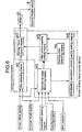
- the electronic control unit U includes a well-known traction control system and an at-start driving force control system added to the traction control system.
- the traction control system includes a slip detecting means M1 for detecting a slip rate of each of the driven wheels W FL and W FR based on the driven wheel speed FL and FR and the follower wheel speed RL and RR.
- the traction control system also includes a driving force control means M2 for suppressing an excessive slip by driving the second throttle valve 8 using the motor 9 to reduce the power output from the engine E, when the excessive slip has been generated in the driven wheels W FL and W FR .
- the at-start driving force control device includes: an operational state detecting means M3 for detecting the operational state of the vehicle V based on the driven wheel speeds FL and FR, the follower wheel speeds RL and RR, the accelerator opening degree ⁇ th1, the steering angle ⁇ st and the shift position; a starting-state detecting means M4 for detecting that the vehicle V is in a starting-state; an initial control quantity setting means M5 for setting an initial torque TQ2 for the driven wheels W FL and W FR based on an output from the operational state detecting means M3 and an output from the starting-state detecting means M4 in order to prevent suspension judder at the start of the vehicle V; an accelerating increment control quantity setting means M6 for setting an accelerating increment torque TQ3 for correcting the initial torque TQ2 to an increased level based on an output from the operational state detecting means M3 in order to insure an acceleratability of the vehicle V after the suspension judder is avoided; and the driving force control means M2.
- Step S1 it is judged at Step S1 whether the entire driving force control system is functioning normally. If there is an abnormality, the processing is passed to a fail-safe routine at Step S2. Then it is judged at Step S33 whether a control-completion flag is in an ON state, and it is judged at Step S3 whether the traction control system is in an ON state. At Step S4, it is judged whether a control-starting flag is in an ON state, and at Step S5, it is judged whether a shift position detected by the shift position sensor 6 indicates the transmission is in first gear.
- Step S6 it is judged whether an accelerator opening degree ⁇ th1 detected by the accelerator opening degree sensor 3 is equal to or greater than a reference value THL, and at Step S7, it is judged whether a vehicle speed (RL + RR)/2 calculated as an average value of the follower wheel speeds detected by the follower wheel speed sensors 1 RL and 1 RR , is equal to or less than a reference value VVL. If NO at Step S33, YES at Step S3, NO at Step S4, YES at Step S5, YES at Step S6 and YES at Step S7, then it is determined that conditions for starting the control of driving force at the start of the vehicle have been established, and at Step S8, the control starting flag is turned ON.
- Step S5 When all of the conditions at Steps S5, S6 and S7 have been established and the control starting flag has just been turned ON, or when the control starting flag is already turned ON at Step S4, if the vehicle speed (RL + RR)/2 has exceeded the reference value VVL at Step S9, or if the accelerator opening degree ⁇ th1 is equal to or less than the reference value THL at Step S10, or if the shift position is other than first gear at step 11, it is judged that the conditions for starting the control of driving force at the start of the vehicle have not been established.
- Step S12 the control starting flag is turned OFF, and at Step S36, the control completion flag is turned OFF.
- control completion flag When the control completion flag is in the ON state at Step S33, if the vehicle speed is equal to or less than the preset value at Step S34, or if the gear shift is other than in first gear at Step S35, the control starting flag is turned OFF at Step S12, and the control completion flag is turned OFF at Step S36.
- Step S13 When the control completion flag is turned OFF and the control starting flag is turned ON to meet the conditions for starting control of the driving force at the start of the vehicle, the processing is passed to Step S13, at which the accelerator opening degree ⁇ th1 is read by the accelerator opening degree sensor 3, and the steering angle ⁇ st is read by the steering angle sensor 5 at Step S14.
- Step S15 it is judged at Step S15 whether a TQ1 delay completion flag has been turned ON.
- the TQ1 delay completion flag is initially in an OFF state. As soon as the control delay starting flag has been turned ON, a timer starts counting. After a lapse of a TQ1 delay time (e.g., 60 m sec), the TQ1 delay completion flag is turned ON. A first loop after the control starting flag is turned ON, the TQ1 delay completion flag is in the OFF state and the answer at Step S15 is "NO". Therefore, the processing is advanced to Step S16, at which a control starting torque TQ1 is set.
- the control starting torque TQ1 is used in place of the initial torque TQ2. Specifically, the control starting torque TQ1 is determined as a maximum torque when the steering angle ⁇ st is 0 (zero) in an initial torque TQ2 map shown in Fig. 2. An excessive control can be prevented by using the control starting torque TQ1 in place of the initial torque TQ2 until the TQ1 delay time is lapsed.
- the control starting torque TQ1 is set at Step S16, and a TQ1 delay processing for controlling the opening degree of the second throttle valve 8 based on the control starting torque TQ1, is carried out at Step S17. If the TQ1 delay time has been lapsed at Step S18, a TQ1 delay completion flag is turned ON.
- the control starting torque TQ1 is converted into the opening degree of the second throttle valve 8 at Step S20.
- the traction control system is in operation at Step S21, the smaller of the opening degree of the second throttle valve 8 based on the traction control and the opening degree of the second throttle valve 8 based on the control starting torque TQ1 is selected at Step S22.
- the motor 9 for the second throttle valve 8 is driven at Step S23, so that the selected opening degree of the second throttle valve 8 is obtained.
- the processing is returned to Step S1.
- Step S24 If the opening degree of the second throttle valve 8 has become equal to or greater than the predetermined value at Step S24, the second throttle valve 8 is fully opened at Step S39. Then, the control completion flag is turned ON at Step S40, and the TQ1 delay flag and the TQ2 delay flag are turned OFF at Step S41, returning to Step S1.
- Step S25 If the answer at Step S15 becomes "YES” at Step S15 after lapse of the TQ1 delay time, it is judged at Step S25 whether a TQ2 delay completion flag has been turned ON.
- the TQ2 delay completion flag is initially in an OFF state. As soon as the TQ1 delay completion flag is turned ON, a timer starts counting, and if a TQ2 delay time (which will be described hereinafter) has elapsed, the TQ2 delay completion flag is turned ON. In a first loop after the TQ1 delay completion flag is turned ON, the TQ2 delay completion flag is in an OFF state and thus, the answer at Step S25 is "NO" and therefore, the processing is advanced to Step S26 at which an initial torque TQ2 is calculated.
- the initial torque TQ2 is determined from the accelerator opening degree ⁇ th1 detected by the accelerator opening degree sensor 3 and the steering angle ⁇ st detected by the steering angle sensor 5 based on the initial torque TQ2 map shown in Fig. 2.
- the initial torque TQ2 is set at a value at which no suspension judder is generated on a wet asphalt road surface or the like.
- a TQ2 delay time is determined from the accelerator opening degree ⁇ th1 and the steering angle ⁇ st based on the initial torque TQ2 map shown in Fig. 2.
- the TQ2 delaying processing for controlling the opening degree of the second throttle valve 8 based on the initial torque TQ2 is carried out.
- the TQ2 delay completion flag is OFF at Step S25, the initial torque TQ2 is calculated at Step S26, and the TQ2 delay time is calculated at Step S27. Then, the TQ2 delaying processing for controlling the opening degree of the second throttle valve 8 based on the initial torque TQ2 is carried out at Step S28. If the TQ2 delay time has elapsed at Step S29, the TQ2 delay completion flag is turned ON at Step S30.
- the motor 9 for the second throttle valve 8 is driven based on the initial torque TQ2 at Steps S20 to S23.
- the initial torque TQ2 has been set at the value at which no suspension judder is generated. Therefore, even if the accelerator pedal has been largely depressed immediately after start of the vehicle V, an increase in driven wheel torque can be suppressed to prevent any suspension judder and to provide a starting performance with a good-feeling and less vibration.
- the initial torque TQ2 is calculated using the accelerator opening degree ⁇ th as a parameter and therefore, it is possible to correct the non-linearity of an engine output with respect to the accelerator opening degree ⁇ th and to establish arbitrary output characteristic which fits a driver's intention.
- the initial torque TQ2 is calculated using the steering angle ⁇ st as a parameter, it is possible to distinguish between the straight travel and turning of the vehicle V to appropriately correct the driven wheel torque.
- Step S31 the processing is advanced to Step S31, at which an accelerating increment torque TQ3 is calculated.
- the accelerating increment torque TQ3 is determined from the accelerator opening degree ⁇ th1 and the steering angle ⁇ st based on the accelerating increment torque TQ3 map shown in Fig. 2.
- a torque TQ(k) during acceleration (which will be referred to as a during-acceleration torque, hereinafter) is calculated by adding the initial torque TQ2 and the accelerating increment torque TQ3 to each other.
- the motor 9 for the second throttle valve 8 is driven based on the during-acceleration torque TQ(k).
- the throttle opening degree corresponding to the during-acceleration torque TQ(k) is equal to or less than the accelerator opening degree (at Step S6) at the start of the control at Step S37, the throttle opening degree corresponding to the during-acceleration torque TQ(k) is fixed at an accelerator opening degree at the start of the control at Step S38.
- the value of the accelerating increment torque TQ3 is set such that the magnitude of the during-acceleration torque TQ(k) becomes a value which permits the vehicle V to be effectively accelerated without increasing the excessive slip of the driven wheels W FL and W FR . Therefore, if a possibility of generation of suspension judder is eliminated after the lapse of the TQ2 delay time, the driven wheel torque can be increased by the during-acceleration torque TQ(k) to exhibit the accelerating performance of the vehicle V to the maximum.
- Step S24 If the opening degree of the second throttle valve 8 is equal to or more than the predetermined value at Step S24, the control of the driving force at the start is completed at Steps S39 to S41 and changed to a normal traction control.
- the second throttle valve 8 of the tandem throttle valve arrangement has been employed as the means for limiting the driving force for the driven wheels W FL and W FR in the embodiment, a linkless throttle valve for electrically controlling the opening and closing of a single throttle valve in accordance with an accelerator opening degree and various parameters can be used in place of the tandem type second throttle valve. Further, an ignition-timing control device, a fuel injection amount control device, a braking-operation control device and/or the like can be used.
- the driving force control system includes the operational state detecting means for detecting the operational state of the vehicle.
- the starting-state detecting means detects the starting-state of the vehicle, and the initial control quantity setting means sets the initial control quantity for the driving force at the start of the vehicle in accordance with the output from the operational state detecting means, when it is determined based on the output from the starting-state detecting means, that the vehicle is in the starting-state.
- the initial control quantity set by the initial control quantity setting means at the start of the vehicle is delivered to the driving force control means to limit the driving force for the driven wheel. Therefore, it is possible to prevent suspension judder from being generated due to an excessive driving force immediately after the start of the vehicle, thereby providing a starting performance with less vibration and a good feeling.
- the limiting of the driving force for the driven wheel based on the initial control quantity is continued until a predetermined time has lapsed after the start of the vehicle. Therefore, it is possible to effect the accurate control of the driving force over a period in which suspension judder is liable to be generated.
- the driving force control system further includes an accelerating increment control quantity setting means for setting an accelerating increment control quantity which is added to the initial control quantity when accelerating the vehicle. Therefore, it is possible to enhance the accelerating performance of the vehicle.
- the accelerating increment control quantity is added to the initial control quantity after the lapse of a predetermined time after the start of the vehicle. Therefore, it is possible to effectively reconcile the prevention of suspension judder and the enhancement in acceleration.
Landscapes
- Engineering & Computer Science (AREA)
- Transportation (AREA)
- Mechanical Engineering (AREA)
- Chemical & Material Sciences (AREA)
- Combustion & Propulsion (AREA)
- Automation & Control Theory (AREA)
- Control Of Vehicle Engines Or Engines For Specific Uses (AREA)
- Electrical Control Of Air Or Fuel Supplied To Internal-Combustion Engine (AREA)
- Combined Controls Of Internal Combustion Engines (AREA)
- Auxiliary Drives, Propulsion Controls, And Safety Devices (AREA)
- Control Of Throttle Valves Provided In The Intake System Or In The Exhaust System (AREA)
Claims (6)
- Antriebskraftsteuersystem in einem Fahrzeug, umfassend:wobei die Ausgangssteuergröße (TQ2) durch das Ausgangssteuergrößeneinstellmittel (M5) beim Anfahren des Fahrzeugs abhängig von einem Plan eingestellt wird, der zuvor basierend auf dem Beschleunigeröffnungsgrad (th1) und dem Lenkwinkel (st) vorbereitet wurde, eingestellt wird, und angelegt wird an dem Antriebskraftsteuermittel (M2), um die Antriebskraft an dem Antriebsrad zu begrenzen.(a) ein Schlupferfassungsmittel (M1) zum Erfassen des Schlupfs eines Antriebsrads (WFL, WFR) eines Fahrzeugs (V);(b) ein Antriebskraftsteuermittel (M2), das mit Schlupferfassungsmittel verbunden ist, um die Antriebskraft auf das Antriebsrad zu begrenzen, wenn das Schlupferfassungsmittel einen übermäßigen Schlupf des Antriebsrads erfaßt;(c) ein Fahrzeugzustandsensormittel, welches Antriebsradgeschwindigkeitssensormittel (1FL, 1FR), Mitlaufradgeschwindigkeitssensormittel (1RL, 1RR), Beschleunigeröffnungsgradsensormittel (3), Lenkwinkelsensormittel (5) und Schaltstellungssensormittel (6) aufweist;(d) ein Betriebszustanderfassungsmittel (M3), welches einen Betriebszustand des Fahrzeugs als eine Funktion der folgenden Ausgaben bestimmt: eine Antriebsradgeschwindigkeit (FL, FR), die durch das Antriebsradgeschwindigkeitssensormittel (1FL, 1FR) erfaßt wird, eine Mitlaufradgeschwindigkeit (RL, RR), die durch das Mitlaufradgeschwindigkeitssensormittel (1RL, 1RR) erfaßt wird, ein Beschleunigeröffnungsgrad (th1), der durch das Beschleunigeröffnungsgradsensormittel (3) erfaßt wird, ein Lenkwinkel (st), der durch das Lenkwinkelsensormittel (5) erfaßt wird, und eine Schaltstellung, die durch das Schaltstellungssensormittel (6) erfaßt wird;(e) ein Anfahrzustanderfassungsmittel (M4), welches einen Anfahrzustand des Fahrzeugs erfaßt; und(f) ein Ausgangssteuergrößeneinstellmittel (M5), welches mit dem Betriebszustanderfassungsmittel (M3) und dem Anfahrzustanderfassungsmittel (M4) verbunden ist, welches eine Ausgangssteuergröße (TQ2) für die Antriebskraft beim Anfahren des Fahrzeugs entsprechend den Ausgaben (th1, st) des Beschleunigeröffnungsgradsensormittels (3) und des Lenkwinkelsensormittels (5) des Fahrzeugzustandsensormittels einstellt, wenn basierend auf einer Ausgabe des Anfahrzustanderfassungsmittels (M4) bestimmt wird, daß das Fahrzeug in einem Anfahrzustand ist;
- Antriebskraftsteuersystem in einem Fahrzeug nach Anspruch 1, umfassend Mittel zum Begrenzen der Antriebskraft für das Antriebsrad basierend auf der Ausgangssteuergröße (TQ2), bis eine vorbestimmte Zeit nach dem Anfahren des Fahrzeugs verstrichen ist.
- Antriebskraftsteuersystem in einem Fahrzeug nach Anspruch 2, ferner umfassend ein Beschleunigungsinkrementsteuergrößeneinstellmittel (M6) zum Einstellen einer Beschleunigungsinkrementsteuergröße (TQ3), die zu der Ausgangssteuergröße (TQ2) addiert wird, wenn das Fahrzeug beschleunigt.
- Antriebskraftsteuersystem in einem Fahrzeug nach Anspruch 3, wobei die Beschleunigungsinkrementsteuergröße (TQ3) zu der Ausgangssteuergröße (TQ2) addiert wird, nachdem eine vorbestimmte Zeit nach dem Anfahren des Fahrzeugs verstrichen ist.
- Antriebskraftsteuersystem in einem Fahrzeug nach Anspruch 1, wobei das Ausgangssteuergrößeneinstellmittel (M5) Mittel zum Erzeugen eines gewünschten Drehmomentsignals als eine Funktion des Beschleunigeröffnungsgrads aufweist.
- Antriebskraftsteuersystem in einem Fahrzeug nach Anspruch 5, wobei das Mittel zum Erzeugen eines gewünschten Drehmomentsignals das Signal nach einer vorbestimmten, verstrichenen Zeit erzeugt.
Applications Claiming Priority (3)
| Application Number | Priority Date | Filing Date | Title |
|---|---|---|---|
| JP04919294A JP3160741B2 (ja) | 1994-03-18 | 1994-03-18 | 車両の駆動力制御装置 |
| JP49192/94 | 1994-03-18 | ||
| JP4919294 | 1994-03-18 |
Publications (3)
| Publication Number | Publication Date |
|---|---|
| EP0672555A2 EP0672555A2 (de) | 1995-09-20 |
| EP0672555A3 EP0672555A3 (de) | 1997-07-09 |
| EP0672555B1 true EP0672555B1 (de) | 2000-03-15 |
Family
ID=12824159
Family Applications (1)
| Application Number | Title | Priority Date | Filing Date |
|---|---|---|---|
| EP95103983A Expired - Lifetime EP0672555B1 (de) | 1994-03-18 | 1995-03-17 | Antriebskraft-Steuerungssystem in einem Fahrzeug |
Country Status (4)
| Country | Link |
|---|---|
| US (1) | US5575350A (de) |
| EP (1) | EP0672555B1 (de) |
| JP (1) | JP3160741B2 (de) |
| DE (1) | DE69515540T2 (de) |
Families Citing this family (4)
| Publication number | Priority date | Publication date | Assignee | Title |
|---|---|---|---|---|
| JP3652403B2 (ja) * | 1995-05-01 | 2005-05-25 | 本田技研工業株式会社 | 前後輪駆動車両 |
| JP4865652B2 (ja) * | 2007-08-03 | 2012-02-01 | 本田技研工業株式会社 | 走行速度制限装置 |
| DE102010009665B4 (de) * | 2010-02-27 | 2017-08-03 | Bayerische Motoren Werke Aktiengesellschaft | Verfahren zur Steuerung des Drehmoments eines Antriebsmotors in einem Kraftfahrzeug |
| JP5706141B2 (ja) * | 2010-12-02 | 2015-04-22 | ダイムラー・アクチェンゲゼルシャフトDaimler AG | ハイブリッド電気自動車の制御装置 |
Family Cites Families (9)
| Publication number | Priority date | Publication date | Assignee | Title |
|---|---|---|---|---|
| JPH07122412B2 (ja) * | 1985-12-19 | 1995-12-25 | 日本電装株式会社 | 内燃機関駆動車両の加速制御装置 |
| SE466143B (sv) * | 1987-04-17 | 1992-01-07 | Honda Motor Co Ltd | Traktionsregleranordning foer fordon |
| US5172319A (en) * | 1989-11-13 | 1992-12-15 | Honda Giken Kogyo Kabushiki Kaisha | Drive wheel slip control system for vehicle |
| JP2894752B2 (ja) * | 1989-12-06 | 1999-05-24 | マツダ株式会社 | 車両のスリップ制御装置 |
| JP2913822B2 (ja) * | 1990-11-14 | 1999-06-28 | トヨタ自動車株式会社 | 加速スリップ制御装置 |
| DE69219650T2 (de) * | 1991-03-13 | 1997-12-18 | Mitsubishi Motors Corp | Gangwechsel-Steuerverfahren für automatisches Fahrzeuggetriebe |
| JP2974440B2 (ja) * | 1991-03-22 | 1999-11-10 | 株式会社日立製作所 | 自動車総合制御装置 |
| US5279382A (en) * | 1991-10-18 | 1994-01-18 | Nissan Motor Co., Ltd. | Traction control system for automotive vehicle and traction control method therefor |
| JP2704804B2 (ja) * | 1992-02-04 | 1998-01-26 | 本田技研工業株式会社 | 車両のトラクションコントロール装置 |
-
1994
- 1994-03-18 JP JP04919294A patent/JP3160741B2/ja not_active Expired - Fee Related
-
1995
- 1995-03-17 US US08/405,241 patent/US5575350A/en not_active Expired - Lifetime
- 1995-03-17 EP EP95103983A patent/EP0672555B1/de not_active Expired - Lifetime
- 1995-03-17 DE DE69515540T patent/DE69515540T2/de not_active Expired - Lifetime
Also Published As
| Publication number | Publication date |
|---|---|
| EP0672555A3 (de) | 1997-07-09 |
| JPH07259595A (ja) | 1995-10-09 |
| US5575350A (en) | 1996-11-19 |
| EP0672555A2 (de) | 1995-09-20 |
| DE69515540D1 (de) | 2000-04-20 |
| JP3160741B2 (ja) | 2001-04-25 |
| DE69515540T2 (de) | 2000-06-29 |
Similar Documents
| Publication | Publication Date | Title |
|---|---|---|
| US4722411A (en) | Wheel slip control system | |
| US4811808A (en) | Acceleration slip control device for a wheeled vehicle | |
| CA2136799C (en) | Driving-force control system for a vehicle | |
| USRE38241E1 (en) | Continuously variable transmission control method and apparatus | |
| US5366039A (en) | Acceleration slip control device for a motor vehicle | |
| EP0672555B1 (de) | Antriebskraft-Steuerungssystem in einem Fahrzeug | |
| KR19980032863A (ko) | 차량의 구동력 제어장치 | |
| KR19990028329A (ko) | 구동토크조정방법및장치 | |
| KR100211099B1 (ko) | 자동차의 내연기관으로부터 차륜으로 유도된 구동력을 제어하는 장치 및 방법 | |
| JP2002525240A (ja) | 車両駆動の調節装置および方法 | |
| EP0575920B1 (de) | Antriebssteuervorrichtung bei der die Antriebskraft erhöht wird, wenn ein Abwürgungszustand detektiert wird | |
| JPH0610435B2 (ja) | 車両の加速スリツプ制御装置 | |
| JP3204079B2 (ja) | 車両用駆動力制御装置 | |
| JP3447680B2 (ja) | 車両の駆動力制御装置 | |
| JP3719032B2 (ja) | 無段変速機を装備した車両の駆動力制御装置 | |
| KR100293676B1 (ko) | 트랙션제어시스템의목표속도설정방법 | |
| JPH11291789A (ja) | 車両用走行制御装置 | |
| JP3106968B2 (ja) | 車速制限装置 | |
| JP3478102B2 (ja) | 自動車のスリップ率制御装置 | |
| JP2888094B2 (ja) | 車両用駆動力制御装置 | |
| JP2669652B2 (ja) | 自動車のスリップ制御装置 | |
| KR0145344B1 (ko) | 차량용 구동력 제어장치 | |
| JPS61247521A (ja) | 車両のスキツド制御装置 | |
| JP2910473B2 (ja) | 車両用駆動力制御装置 | |
| JPS63113131A (ja) | 車両スリツプ制御装置 |
Legal Events
| Date | Code | Title | Description |
|---|---|---|---|
| PUAI | Public reference made under article 153(3) epc to a published international application that has entered the european phase |
Free format text: ORIGINAL CODE: 0009012 |
|
| AK | Designated contracting states |
Kind code of ref document: A2 Designated state(s): DE FR GB |
|
| PUAL | Search report despatched |
Free format text: ORIGINAL CODE: 0009013 |
|
| AK | Designated contracting states |
Kind code of ref document: A3 Designated state(s): DE FR GB |
|
| 17P | Request for examination filed |
Effective date: 19971030 |
|
| 17Q | First examination report despatched |
Effective date: 19980612 |
|
| GRAG | Despatch of communication of intention to grant |
Free format text: ORIGINAL CODE: EPIDOS AGRA |
|
| GRAG | Despatch of communication of intention to grant |
Free format text: ORIGINAL CODE: EPIDOS AGRA |
|
| GRAH | Despatch of communication of intention to grant a patent |
Free format text: ORIGINAL CODE: EPIDOS IGRA |
|
| GRAH | Despatch of communication of intention to grant a patent |
Free format text: ORIGINAL CODE: EPIDOS IGRA |
|
| GRAA | (expected) grant |
Free format text: ORIGINAL CODE: 0009210 |
|
| AK | Designated contracting states |
Kind code of ref document: B1 Designated state(s): DE FR GB |
|
| REF | Corresponds to: |
Ref document number: 69515540 Country of ref document: DE Date of ref document: 20000420 |
|
| ET | Fr: translation filed | ||
| PLBE | No opposition filed within time limit |
Free format text: ORIGINAL CODE: 0009261 |
|
| STAA | Information on the status of an ep patent application or granted ep patent |
Free format text: STATUS: NO OPPOSITION FILED WITHIN TIME LIMIT |
|
| 26N | No opposition filed | ||
| REG | Reference to a national code |
Ref country code: GB Ref legal event code: IF02 |
|
| PGFP | Annual fee paid to national office [announced via postgrant information from national office to epo] |
Ref country code: FR Payment date: 20020312 Year of fee payment: 8 |
|
| PGFP | Annual fee paid to national office [announced via postgrant information from national office to epo] |
Ref country code: GB Payment date: 20020320 Year of fee payment: 8 |
|
| PG25 | Lapsed in a contracting state [announced via postgrant information from national office to epo] |
Ref country code: GB Free format text: LAPSE BECAUSE OF NON-PAYMENT OF DUE FEES Effective date: 20030317 |
|
| GBPC | Gb: european patent ceased through non-payment of renewal fee |
Effective date: 20030317 |
|
| PG25 | Lapsed in a contracting state [announced via postgrant information from national office to epo] |
Ref country code: FR Free format text: LAPSE BECAUSE OF NON-PAYMENT OF DUE FEES Effective date: 20031127 |
|
| REG | Reference to a national code |
Ref country code: FR Ref legal event code: ST |
|
| PGFP | Annual fee paid to national office [announced via postgrant information from national office to epo] |
Ref country code: DE Payment date: 20100422 Year of fee payment: 16 |
|
| PG25 | Lapsed in a contracting state [announced via postgrant information from national office to epo] |
Ref country code: DE Free format text: LAPSE BECAUSE OF NON-PAYMENT OF DUE FEES Effective date: 20111001 |
|
| REG | Reference to a national code |
Ref country code: DE Ref legal event code: R119 Ref document number: 69515540 Country of ref document: DE Effective date: 20111001 |