EP0672972A2 - Bilderzeugungsgerät - Google Patents
Bilderzeugungsgerät Download PDFInfo
- Publication number
- EP0672972A2 EP0672972A2 EP95103683A EP95103683A EP0672972A2 EP 0672972 A2 EP0672972 A2 EP 0672972A2 EP 95103683 A EP95103683 A EP 95103683A EP 95103683 A EP95103683 A EP 95103683A EP 0672972 A2 EP0672972 A2 EP 0672972A2
- Authority
- EP
- European Patent Office
- Prior art keywords
- toner
- detecting
- photoconductive drum
- expiry
- collecting box
- Prior art date
- Legal status (The legal status is an assumption and is not a legal conclusion. Google has not performed a legal analysis and makes no representation as to the accuracy of the status listed.)
- Withdrawn
Links
Images


Classifications
-
- G—PHYSICS
- G03—PHOTOGRAPHY; CINEMATOGRAPHY; ANALOGOUS TECHNIQUES USING WAVES OTHER THAN OPTICAL WAVES; ELECTROGRAPHY; HOLOGRAPHY
- G03G—ELECTROGRAPHY; ELECTROPHOTOGRAPHY; MAGNETOGRAPHY
- G03G15/00—Apparatus for electrographic processes using a charge pattern
- G03G15/55—Self-diagnostics; Malfunction or lifetime display
- G03G15/553—Monitoring or warning means for exhaustion or lifetime end of consumables, e.g. indication of insufficient copy sheet quantity for a job
-
- G—PHYSICS
- G03—PHOTOGRAPHY; CINEMATOGRAPHY; ANALOGOUS TECHNIQUES USING WAVES OTHER THAN OPTICAL WAVES; ELECTROGRAPHY; HOLOGRAPHY
- G03G—ELECTROGRAPHY; ELECTROPHOTOGRAPHY; MAGNETOGRAPHY
- G03G15/00—Apparatus for electrographic processes using a charge pattern
- G03G15/55—Self-diagnostics; Malfunction or lifetime display
-
- G—PHYSICS
- G03—PHOTOGRAPHY; CINEMATOGRAPHY; ANALOGOUS TECHNIQUES USING WAVES OTHER THAN OPTICAL WAVES; ELECTROGRAPHY; HOLOGRAPHY
- G03G—ELECTROGRAPHY; ELECTROPHOTOGRAPHY; MAGNETOGRAPHY
- G03G21/00—Arrangements not provided for by groups G03G13/00 - G03G19/00, e.g. cleaning, elimination of residual charge
- G03G21/10—Collecting or recycling waste developer
- G03G21/12—Toner waste containers
-
- G—PHYSICS
- G03—PHOTOGRAPHY; CINEMATOGRAPHY; ANALOGOUS TECHNIQUES USING WAVES OTHER THAN OPTICAL WAVES; ELECTROGRAPHY; HOLOGRAPHY
- G03G—ELECTROGRAPHY; ELECTROPHOTOGRAPHY; MAGNETOGRAPHY
- G03G2221/00—Processes not provided for by group G03G2215/00, e.g. cleaning or residual charge elimination
- G03G2221/16—Mechanical means for facilitating the maintenance of the apparatus, e.g. modular arrangements and complete machine concepts
- G03G2221/1618—Mechanical means for facilitating the maintenance of the apparatus, e.g. modular arrangements and complete machine concepts for the cleaning unit
-
- G—PHYSICS
- G03—PHOTOGRAPHY; CINEMATOGRAPHY; ANALOGOUS TECHNIQUES USING WAVES OTHER THAN OPTICAL WAVES; ELECTROGRAPHY; HOLOGRAPHY
- G03G—ELECTROGRAPHY; ELECTROPHOTOGRAPHY; MAGNETOGRAPHY
- G03G2221/00—Processes not provided for by group G03G2215/00, e.g. cleaning or residual charge elimination
- G03G2221/16—Mechanical means for facilitating the maintenance of the apparatus, e.g. modular arrangements and complete machine concepts
- G03G2221/1663—Mechanical means for facilitating the maintenance of the apparatus, e.g. modular arrangements and complete machine concepts having lifetime indicators
Definitions
- the present invention relates to an image forming apparatus such as an electrophotographic apparatus, information recording apparatus or the like.
- the image forming apparatus of this type is adapted to store in a toner collecting box, toner to be discarded (hereinafter referred to as toner waste) which is collected by a cleaning unit from the surface of a photoconductive drum after image transfer and thence before the toner collecting box becomes full, it must be detected timely by proper detecting means so that the toner waste may be discarded from the apparatus.
- toner waste toner to be discarded
- the toner collecting box is adapted to become full just as the photoconductive drum ends its service life.
- the toner collecting box would often become full before exchanging the photoconductive drums because the use of toner is within a range of normal operations but beyond the range of the aforesaid given operational conditions. Additionally, there are some actual cases where a volume of toner collected by a toner collector is abnormally large due to the occurrence of some abnormality.
- an object of the present invention to provide an image forming apparatus which not only assures under normal operational conditions that the exchange of photoconductive materials and the disposal of collected toner can be carried out simultaneously but also enables it to give a warning of abnormality in the process if this cannot be attained.
- the toner collecting box has a capacity exceeding the maximum volume of toner to be used under normal operational conditions within the service life of the photoconductive material, and hence the toner collecting box does not become full before exchanging the photoconductive materials. Accordingly, it is ensured that the exchange of the photoconductive materials and the disposal of collected toner can be conducted at the same time.
- the toner collecting box has a capacity exceeding the maximum volume of toner to be used under normal operational conditions within the service life of the photoconductive material, and therefore, if the fullness detecting means should detect that the toner collecting box is full of toner before the life expiry detecting means detects the expiry of the service life of the photoconductive material, such a state will be judged to be abnormal and the abnormality warning means will be caused to indicate abnormality.
- an operator can take a proper measure, e.g., calling a service man.
- the main body of the copying machine 1 includes therein (1) an optical system 3 for illuminating and scanning an original placed on a transparent platen 2 and focusing image rays reflected from the illuminated original onto a photoconductive drum 42, (2) an image processing portion 4 wherein an latent electrostatic image produced on the photoconductive drum 42 is developed into a toner image by a developing unit 41 and thereafter the image thus developed is transferred to a sheet of copy paper, and (3) a paper transport portion 5 which draws out the aforesaid copy paper from a paper feed tray 61 in a paper containing portion 6 by means of a paper take-up roll 51 having a semi-circular form in section and conveys the paper through the image processing portion 4 to a copy tray 56 in the main body of the copying machine.
- an optical system 3 for illuminating and scanning an original placed on a transparent platen 2 and focusing image rays reflected from the illuminated original onto a photoconductive drum 42
- an image processing portion 4 wherein an latent electrostatic image produced on the photo
- the main body 1 comprises a lower unit 7 defined by a lower casing 71, and an upper unit 8 defined by an upper casing 81 relatively turnablly supported with respect to the lower unit 7 around a predetermined pivotal axis m disposed at an end thereof.
- the main body 1 has a so-called clam-shell type structure wherein the upper unit 8 is openable as relatively turned with respect to the lower unit 7.
- the optical system 3 illuminates a document original by means of a fluorescent lamp 39 with a reflector 38 which is secured to a first shift frame 3A, and focuses image rays reflected from the document original onto the photoconductive drum 42 sequentially thorough a first mirror 31 secured to the first shift frame 3A, a second mirror 32, a third mirror 33 and a lens 37 secured to a second shift frame 3B, a fourth mirror 34, a fifth mirror 35 and a sixth mirror 36 secured to a third shift frame 3C.
- the image processing portion 4 has a drum charge corona 43, the developing unit 41, an image transfer corona 44 and a cleaning unit 45 disposed around the photoconductive drum 42 in the order named.
- the image processing portion 4 is adapted such that a latent electrostatic image is produced by focusing image rays reflected from the document original on the outer peripheral surface of the uniformly charged photoconductive drum 42; thereafter the latent electrostatic image thus produced is developed into a toner image by the developing unit 41; the toner image so developed is transferred to a sheet of copy paper by the image transfer corona 44; and the residual toner is recovered by the cleaning unit 45.
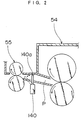
- the paper transport portion 5 comprises the aforesaid paper take-up roll 51 for sequentially drawing out a copy paper from the paper feed tray 61, a transport roller 52 for advancing the copy paper from a manual feed portion 60 or the paper feed tray 61, a drive roller 53a and a driven roller 53b serving as resist means 53 against which the leading edge of the paper conveyed by the transport roller 52 abuts to thereby halt the paper temporarily, a fixing portion 54 for fixing the toner image transferred to the paper, and a pair of discharge rollers 55.
- a paper discharge detecting sensor 140 for detecting the exit of a copy paper comprising a limit switch, is disposed between the aforesaid fixing portion 54 and the discharge rollers 55.
- the paper discharge detecting sensor 140 has an upright operating stick 140a intruded into a paper transport passage P.
- the operating stick 140a becomes in a state shown by a dashed line in the figure as tumbled by the leading edge of the paper transported along the paper transport passage P, to output an ON signal, and returns to the initial upright state responding to the passage of the trailing edge of the paper.
- the aforesaid cleaning unit 45 has a storage 104 (see Fig. 5) for accommodating toner waste scraped off from the circumferential surface of the photoconductive drum 42.
- a reed switch 130 for detecting that the storage 104 is filled up with toner waste is disposed above the cleaning unit 45. Referring to Fig. 1, the output of the reed switch 130 is supplied to a control unit 150.
- the output of the aforesaid paper discharge detecting sensor 140 is supplied to the control unit 150 which multiplies the number of the aforesaid outputs as supplied, to find a cumulative number of produced copies N.
- control unit 150 sends a signal, causing a liquid crystal display unit 10 (see Fig. 3) provided on the upper surface of the main body 1 to display a message indicating that the photoconductive drum 42 has ended its service life.
- This embodiment of the present invention determines the expiry of the service life of a photoconductive drum 42 from the number of copies produced.
- the embodiment of the present invention is characterized by that (1) the capacity of the aforesaid storage 104 is adapted to exceed the maximum volume of toner to be used under normal operational conditions within the service life of the photoconductive drum 42, and that (2) if the reed switch 130 detects that the storage is full before the expiry of the service life of the photoconductive drum 42, the control unit 150 sends a signal to cause the display unit 10 to show a message indicating that the use of toner is abnormally large.
- a unit U comprising the aforesaid cleaning unit 45 and photoconductive drum 42 is integrally detachable from the main body 1.
- the unit U has a pair of retainers U1, U2 for supporting the both ends of the photoconductive drum 42.
- the aforesaid cleaning unit 45 has a cleaning housing 101 including an opening 101a opposite to the photoconductive drum 42.
- the cleaning housing 101 comprises an upper housing 121 and a lower housing 122 which are removably fixed to each other by the use of screws.
- the interior of the cleaning housing 101 is divided by a sectionally L-shaped partition 102 into a cleaning chamber 103 for scraping toner off from the surface of the photoconductive drum 42 and the storage 104 in which the toner thus scraped off is stored.
- the aforesaid storage 104 of the cleaning housing 101 also serves as the toner collecting box.
- the aforesaid storage 104 includes therein a detecting plate 125 opposing a top plate 121a of the upper housing 121, vertically movably supported by two pairs of ribs 123 and 124 protruding downward from the top plate 121a.
- the detecting plate 125 comprises a thin plate made of flexible metal (e.g. aluminum) and has a permanent magnet 127 provided at the center of the upper surface 125a thereof by means of a sponge member 125 as resilient supporting means having a certain level of resilience.
- the sponge member 126 has a rectangular parallelopiped shape, being bonded to the upper surface of the aforesaid detecting plate 125.
- the permanent magnet 127 has a rectangular parallelopiped shape, being bonded to the upper surface of the sponge member 126.
- the reed switch 130 as means for detecting the fullness of the storage as actuated in response to the magnetic force of the permanent magnet 127 is disposed at a place opposing the aforesaid permanent magnet 127, which has reached the uppermost position, with the top plate 121a interposed therebetween.
- An output of the reed switch 130 is supplied to the control unit 150 which, on receiving the aforesaid output, sends a signal to the display unit 10 thereby to cause the same to inform an operator that, for example, the storage is full.
- the aforementioned ribs 123 are shaped like a column and penetrate through-holes 125b of the detecting plate 125.
- the through-holes 125b are opposite to each other with the aforesaid permanent magnet 127 interposed therebetween.
- the aforesaid ribs 124 have an elongated section extending along the longitudinal direction of the detecting plate 125 and penetrate through-holes 125c defined at positions opposite to each other with the aforesaid permanent magnet 127 interposed therebetween and beyond the aforesaid through-holes 125b.
- the rib 124 has a machine screw 128 threaded in the lower end thereof, thereby preventing the detecting plate 125 from dropping off from the rib 124.
- clearance between the through-holes 125b, 125c and the ribs 123, 124 corresponding thereto respectively is adapted such that some degree of inclination or deflection of the detecting plate 125 may be allowed. More specifically, in Fig. 6, the detecting plate 125 is allowed to swingably incline in the direction shown by the arrow M in the figure or in the direction shown by the arrow N about the longitudinal axis L of the detecting plate 125. Thus, the detecting plate 125 is imparted with such a degree of freedom as to follow an inclination of the upper surface of toner waste accumulated in the storage 104.
- a main blade 105 the lower end of which is in contact with the circumferential surface of the photoconductive drum 42.
- the main blade 105 is fixed to the cleaning housing 101 by way of a mounting element 110 so that in association with the rotation of the photoconductive drum 42, the aforesaid lower end thereof scrapes off toner remaining on the surface of the photoconductive drum 42.
- a receptive blade 106 made of rubber or the like is provided at the lower part of the opening 101a to cover this lower part. The upper edge of the receptive blade 106 is in close proximity to the circumferential surface of the photoconductive drum 42 thus preventing outward scattering of toner scraped down in the cleaning housing 101.
- a cleaning roller 107 is provided with most part thereof being disposed within the cleaning chamber 103 while a part thereof protruded into the storage 104.
- the cleaning roller 107 is rotatably supported by the cleaning housing 101 and is in contact with the circumferential surface of the photoconductive drum 42 through the aforesaid opening 101a to be rotated in association with the rotation of the photoconductive drum 42.
- the photoconductive drum 42 is rotated clockwise, and so the cleaning roller 107 is rotated counterclockwise.
- the cleaning roller 107 displaces toner or paper particle adhered to the circumferential surface of the photoconductive drum 42 over the same surface, so that the main blade 105 may easily scrape off the toner or the like off the circumferential surface of the photoconductive drum 42.
- a clearance S between the lower edge 102b of the aforesaid partition 102 and the circumferential surface of the cleaning roller 107 is preferably set in a range from 1 to 2 mm, more particularly from 1.3 to 1.5 mm.
- the cleaning roller 107 can smoothly convey toner in the cleaning chamber 103 to the storage 104 through the clearance S. This avoids unwanted accumulation of toner in the cleaning chamber 103, thereby maintaining an excellent cleaning ability for a long period of time.
- the cleaning roller 107 serving as a transport roller having a sufficient conveying ability the structure is made simpler, smaller and less expensive than that providing a separate transport member.
- an inclined scraper 108 Under a position where the aforesaid cleaning roller 107 is in close proximity to the lower edge 102b of the partition 102, an inclined scraper 108 has the upper edge thereof abut against the circumferential surface of the cleaning roller 107.
- the scraper 108 is secured to a mounting element 109, which is supported by a detachable lid member 111 constituting a part of the bottom of the cleaning housing 101.
- the lid member 111 has the aforesaid receptive blade 106 mounted thereto.
- the aforementioned scraper 108 separates the cleaning chamber 103 from the storage 104 by abutting against the cleaning roller 107.
- a sectionally L-shaped transport paddle 112 for advancing toward the depth of the storage 104 (leftward in the figure), toner which is conveyed from the cleaning chamber 103 into the storage 104.
- the transport paddle 112 is rotated in a clockwise direction as viewed in the figure thereby conveying the toner.
- toner scraped off by the main blade 105 into the cleaning chamber 103 is allowed to drop onto the upper part of the cleaning roller 107 to be conveyed through the aforesaid clearance S into the storage 104 according to the rotation of the cleaning roller 107, and further onto the upper surface of the scraper 108.
- the toner on the scraper 108 is conveyed to the deeper side of the storage 104 by the transport paddle 112 to accumulate gradually in the storage 104.
- the detecting plate 125 is carried up by the upper surface of the accumulated toner, to continue rising as inclined normally.
- an end 127a of the permanent magnet 127 touches the lower surface of the top plate 121a, as shown in Fig. 7A. If the detecting plate 125 in this state is further carried up by the increasing toner accumulation, an end 126a of the sponge member 126 supporting the aforesaid end 127a of the permanent magnet 127 is compressed as shown in Fig. 7B, allowing the permanent magnet 127 to restore its horizontal position.
- the inclination of the detecting plate 125 is balanced by the sponge member 126 so that the permanent magnet 127 can squarely oppose the reed switch 130 in a horizontal position along the top plate 121a. This assures detection of the fullness of the storage. Additionally, the repulsive force of the aforesaid compressed end 126a of the sponge member 126 causes a momentum to rotate the detecting plate 125 counterclockwise as viewed in Fig. 7B. This helps return the detecting plate 125 to a horizontal position, thereby leveling off the upper surface of the accumulated toner.
- the sponge member 126 may be replaced by an elastic rubber member or a coiled compression spring having a predetermined level of elasticity.
- the detecting plate 125 may be hung from the top plate 121a by means of cord or wire.
- the aforesaid control unit 150 comprises a microcomputer or the like, primarily controlling the drive of the optical system 3, the image processing portion 4 and the paper transport portion 5.
- the control unit 150 further comprises a non-volatile memory (not shown), which stores the aforesaid cumulative number of produced copies N.
- Step S1 the cumulative number of produced copies N is first read out from the aforesaid non-volatile memory (Step S1) and one is added to the cumulative number of produced copies N in response to a signal from the paper discharge detecting sensor 140 which is output each time an image is transferred onto a copy sheet (Step S2).
- Step S2 the cumulative number of produced copies N reaches a predetermined limit value NL
- the control unit 150 orders to display a message indicating the expiry of the service life of the photoconductive drum 42 (Steps S4, S5).
- control unit 150 causes the display unit 10 to indicate that the use of toner is abnormally large (Steps S6, S7).
- the storage 104 of toner waste has such a capacity that the storage does not become full before the expiry of the service life of the photoconductive drum 42 under normal operational conditions, and therefore, it is ensured that the exchange of the photoconductive drums 42 and the disposal of collected toner waste can be conducted at the same time.
- the control unit 150 judges that the use of toner is abnormally large (it can be presumed, for example, that graphic originals are used much more frequently than normal) and informs its judgment to the operator. In response to this, the operator can take a proper measure, e.g., calling a service man.
- the aforesaid embodiment of the present invention determines the expiry of the service life of the photoconductive drum 42 merely based on the cumulative number of produced copies N regardless of the size of copy paper. For more accurate judgment of the expiry of the service life, however, it may be determined with the cumulative number of produced copies N and the longitudinal length of the copy paper (for example, B4 paper has twice the length of B5 paper) taken into consideration. In this case, the length of the paper is determined by the length of time interval between ON and OFF of the signal of the paper discharge detecting sensor 140.
Landscapes
- Physics & Mathematics (AREA)
- General Physics & Mathematics (AREA)
- Life Sciences & Earth Sciences (AREA)
- Engineering & Computer Science (AREA)
- Environmental & Geological Engineering (AREA)
- Sustainable Development (AREA)
- Cleaning In Electrography (AREA)
- Control Or Security For Electrophotography (AREA)
Applications Claiming Priority (2)
| Application Number | Priority Date | Filing Date | Title |
|---|---|---|---|
| JP06044221A JP3080833B2 (ja) | 1994-03-15 | 1994-03-15 | 画像形成装置 |
| JP44221/94 | 1994-03-15 |
Publications (2)
| Publication Number | Publication Date |
|---|---|
| EP0672972A2 true EP0672972A2 (de) | 1995-09-20 |
| EP0672972A3 EP0672972A3 (de) | 1996-08-28 |
Family
ID=12685494
Family Applications (1)
| Application Number | Title | Priority Date | Filing Date |
|---|---|---|---|
| EP95103683A Withdrawn EP0672972A3 (de) | 1994-03-15 | 1995-03-14 | Bilderzeugungsgerät. |
Country Status (3)
| Country | Link |
|---|---|
| US (1) | US5500716A (de) |
| EP (1) | EP0672972A3 (de) |
| JP (1) | JP3080833B2 (de) |
Cited By (2)
| Publication number | Priority date | Publication date | Assignee | Title |
|---|---|---|---|---|
| GB2301688A (en) * | 1995-05-31 | 1996-12-11 | Samsung Electronics Co Ltd | Maintenance of image forming apparatus |
| EP0672970A3 (de) * | 1994-03-15 | 1997-03-12 | Mita Industrial Co Ltd | Reinigungseinheit. |
Families Citing this family (17)
| Publication number | Priority date | Publication date | Assignee | Title |
|---|---|---|---|---|
| JP3313978B2 (ja) * | 1996-07-26 | 2002-08-12 | キヤノン株式会社 | プロセスカートリッジ及び電子写真画像形成装置 |
| JPH1039685A (ja) * | 1996-07-26 | 1998-02-13 | Canon Inc | 画像形成装置及びプロセスカートリッジ |
| US5918085A (en) * | 1997-04-11 | 1999-06-29 | Xerox Corporation | Method and apparatus for waste toner determination |
| JPH1115339A (ja) * | 1997-06-24 | 1999-01-22 | Canon Inc | 電子写真画像形成装置及びプロセスカートリッジ |
| US6505009B2 (en) * | 2001-06-05 | 2003-01-07 | Hewlett-Packard Company | Waste toner detection systems and methods for determining the volume of waste toner in a printer cartridge |
| US6580881B2 (en) | 2001-10-04 | 2003-06-17 | Lexmark International, Inc. | Method of detecting waste toner in a container of an image forming apparatus |
| US6640061B2 (en) * | 2001-10-11 | 2003-10-28 | Xerox Corporation | Sensing system for detecting a full condition within a waste developer system |
| DE10151703B4 (de) | 2001-10-19 | 2004-12-09 | OCé PRINTING SYSTEMS GMBH | Vorrichtung und Verfahren zum Erfassen der Beschaffenheit einer Tonerteilchenschicht in einem Drucker oder Kopierer |
| US7085507B2 (en) * | 2003-08-25 | 2006-08-01 | Lexmark International, Inc. | Method and apparatus to control waste toner collection in an image forming apparatus |
| JP3951996B2 (ja) * | 2003-09-18 | 2007-08-01 | コニカミノルタビジネステクノロジーズ株式会社 | 画像形成装置 |
| US7205738B2 (en) * | 2004-03-24 | 2007-04-17 | Lexmark International, Inc. | Method and apparatus for time-based dc motor commutation |
| US7257363B2 (en) * | 2005-09-22 | 2007-08-14 | Lexmark International, Inc. | Device for moving toner within an image forming device |
| JP5778933B2 (ja) | 2011-01-28 | 2015-09-16 | キヤノン株式会社 | 印刷装置、印刷装置の制御方法、及びプログラム |
| JP5648516B2 (ja) * | 2011-02-09 | 2015-01-07 | 富士ゼロックス株式会社 | 粉体回収容器の満杯検知装置及びこれを用いた粉体回収装置、並びに画像形成装置 |
| US9523947B2 (en) | 2012-09-26 | 2016-12-20 | Lexmark International, Inc. | Time-based commutation method and system for controlling a fuser assembly |
| US8836747B2 (en) | 2012-10-02 | 2014-09-16 | Lexmark International, Inc. | Motor control system and method for a laser scanning unit of an imaging apparatus |
| JP7388209B2 (ja) * | 2020-01-27 | 2023-11-29 | ブラザー工業株式会社 | 画像形成装置 |
Family Cites Families (6)
| Publication number | Priority date | Publication date | Assignee | Title |
|---|---|---|---|---|
| JPS57154255A (en) * | 1981-03-18 | 1982-09-24 | Canon Inc | Image forming apparatus |
| JPS6126073A (ja) * | 1984-07-16 | 1986-02-05 | Canon Inc | カ−トリツジ |
| JPS6255686A (ja) * | 1985-09-05 | 1987-03-11 | Mita Ind Co Ltd | トナ−回収装置 |
| US4791454A (en) * | 1986-06-05 | 1988-12-13 | Ricoh Company, Ltd. | Removable photoconductive element unit for image-forming apparatus |
| US5008711A (en) * | 1987-04-23 | 1991-04-16 | Ricoh Company, Ltd. | Image forming apparatus |
| JPH05173457A (ja) * | 1991-12-24 | 1993-07-13 | Ricoh Co Ltd | クリーニングユニット |
-
1994
- 1994-03-15 JP JP06044221A patent/JP3080833B2/ja not_active Expired - Fee Related
-
1995
- 1995-03-08 US US08/400,815 patent/US5500716A/en not_active Expired - Lifetime
- 1995-03-14 EP EP95103683A patent/EP0672972A3/de not_active Withdrawn
Cited By (2)
| Publication number | Priority date | Publication date | Assignee | Title |
|---|---|---|---|---|
| EP0672970A3 (de) * | 1994-03-15 | 1997-03-12 | Mita Industrial Co Ltd | Reinigungseinheit. |
| GB2301688A (en) * | 1995-05-31 | 1996-12-11 | Samsung Electronics Co Ltd | Maintenance of image forming apparatus |
Also Published As
| Publication number | Publication date |
|---|---|
| JP3080833B2 (ja) | 2000-08-28 |
| US5500716A (en) | 1996-03-19 |
| EP0672972A3 (de) | 1996-08-28 |
| JPH07253738A (ja) | 1995-10-03 |
Similar Documents
| Publication | Publication Date | Title |
|---|---|---|
| US5500716A (en) | Image forming apparatus which detects waste toner accumulation before photoconductor service life expiration | |
| US5021825A (en) | Latching mechanism for a removable processing cartridge in a photocopying device | |
| US4819578A (en) | Toner collecting device | |
| EP0217173B1 (de) | Gerät zum Sammeln von Toner | |
| JPH0310942B2 (de) | ||
| JP2860918B2 (ja) | クリーナ・トナー・マガジン | |
| JP2001356655A (ja) | 像担持体寿命検知方法、画像形成装置及びカートリッジ | |
| US4435074A (en) | Cleaning apparatus for electrophotography comprising lubricant film applicator means | |
| CN86108832A (zh) | 废调色剂盛满的检测装置 | |
| JPH07253737A (ja) | クリーニング装置 | |
| EP0604191B1 (de) | Entwicklungsvorrichtung und Bilderzeugungsgerät | |
| JPH10186987A (ja) | 画像形成装置 | |
| JP2851365B2 (ja) | 蓄積容器の検出装置 | |
| JP3009584B2 (ja) | トナー回収容器 | |
| JP2939804B2 (ja) | 電子写真記録装置 | |
| JPH10312143A (ja) | 画像形成装置 | |
| JPH08211717A (ja) | トナーカートリッジ | |
| JPH08179627A (ja) | 電子写真装置 | |
| JPH0511619A (ja) | 現像装置 | |
| JPH0766226B2 (ja) | 画像形成装置のトナー回収装置 | |
| JP2001075439A (ja) | 画像形成装置 | |
| JPH01158474A (ja) | クリーニング装置の廃トナー回収機構及び廃トナー回収容器の満杯検知装置 | |
| JPH055576Y2 (de) | ||
| JPH04359261A (ja) | 画像形成装置 | |
| JP3408051B2 (ja) | 現像剤残量検知装置 |
Legal Events
| Date | Code | Title | Description |
|---|---|---|---|
| PUAI | Public reference made under article 153(3) epc to a published international application that has entered the european phase |
Free format text: ORIGINAL CODE: 0009012 |
|
| AK | Designated contracting states |
Kind code of ref document: A2 Designated state(s): DE FR GB IT |
|
| PUAL | Search report despatched |
Free format text: ORIGINAL CODE: 0009013 |
|
| AK | Designated contracting states |
Kind code of ref document: A3 Designated state(s): DE FR GB IT |
|
| STAA | Information on the status of an ep patent application or granted ep patent |
Free format text: STATUS: THE APPLICATION IS DEEMED TO BE WITHDRAWN |
|
| 18D | Application deemed to be withdrawn |
Effective date: 19970301 |