EP0673328B1 - Systeme de direction assistee - Google Patents
Systeme de direction assistee Download PDFInfo
- Publication number
- EP0673328B1 EP0673328B1 EP94930178A EP94930178A EP0673328B1 EP 0673328 B1 EP0673328 B1 EP 0673328B1 EP 94930178 A EP94930178 A EP 94930178A EP 94930178 A EP94930178 A EP 94930178A EP 0673328 B1 EP0673328 B1 EP 0673328B1
- Authority
- EP
- European Patent Office
- Prior art keywords
- power
- electric motor
- steering device
- assisted steering
- current
- Prior art date
- Legal status (The legal status is an assumption and is not a legal conclusion. Google has not performed a legal analysis and makes no representation as to the accuracy of the status listed.)
- Expired - Lifetime
Links
- 239000012530 fluid Substances 0.000 claims abstract description 16
- 238000000034 method Methods 0.000 claims description 16
- 230000007935 neutral effect Effects 0.000 claims description 12
- 230000006870 function Effects 0.000 claims description 10
- 230000015654 memory Effects 0.000 claims description 2
- 238000010586 diagram Methods 0.000 description 10
- 230000001419 dependent effect Effects 0.000 description 9
- 230000008901 benefit Effects 0.000 description 4
- 230000007257 malfunction Effects 0.000 description 4
- 239000003921 oil Substances 0.000 description 4
- 238000005265 energy consumption Methods 0.000 description 3
- 238000004519 manufacturing process Methods 0.000 description 3
- 238000012545 processing Methods 0.000 description 3
- 230000004913 activation Effects 0.000 description 2
- 230000008859 change Effects 0.000 description 2
- 230000001276 controlling effect Effects 0.000 description 2
- 230000006378 damage Effects 0.000 description 2
- 238000011156 evaluation Methods 0.000 description 2
- 238000012544 monitoring process Methods 0.000 description 2
- 238000012360 testing method Methods 0.000 description 2
- 230000002411 adverse Effects 0.000 description 1
- 230000000903 blocking effect Effects 0.000 description 1
- 230000000694 effects Effects 0.000 description 1
- 230000005611 electricity Effects 0.000 description 1
- 238000010438 heat treatment Methods 0.000 description 1
- 239000010720 hydraulic oil Substances 0.000 description 1
- 230000001771 impaired effect Effects 0.000 description 1
- 230000005012 migration Effects 0.000 description 1
- 238000013508 migration Methods 0.000 description 1
- 230000008569 process Effects 0.000 description 1
- 238000004886 process control Methods 0.000 description 1
- 230000001105 regulatory effect Effects 0.000 description 1
- 230000004044 response Effects 0.000 description 1
- 230000035945 sensitivity Effects 0.000 description 1
- 239000010729 system oil Substances 0.000 description 1
Images




Classifications
-
- F—MECHANICAL ENGINEERING; LIGHTING; HEATING; WEAPONS; BLASTING
- F04—POSITIVE - DISPLACEMENT MACHINES FOR LIQUIDS; PUMPS FOR LIQUIDS OR ELASTIC FLUIDS
- F04B—POSITIVE-DISPLACEMENT MACHINES FOR LIQUIDS; PUMPS
- F04B49/00—Control, e.g. of pump delivery, or pump pressure of, or safety measures for, machines, pumps, or pumping installations, not otherwise provided for, or of interest apart from, groups F04B1/00 - F04B47/00
- F04B49/06—Control using electricity
- F04B49/065—Control using electricity and making use of computers
-
- B—PERFORMING OPERATIONS; TRANSPORTING
- B62—LAND VEHICLES FOR TRAVELLING OTHERWISE THAN ON RAILS
- B62D—MOTOR VEHICLES; TRAILERS
- B62D5/00—Power-assisted or power-driven steering
- B62D5/06—Power-assisted or power-driven steering fluid, i.e. using a pressurised fluid for most or all the force required for steering a vehicle
- B62D5/065—Power-assisted or power-driven steering fluid, i.e. using a pressurised fluid for most or all the force required for steering a vehicle characterised by specially adapted means for varying pressurised fluid supply based on need, e.g. on-demand, variable assist
-
- B—PERFORMING OPERATIONS; TRANSPORTING
- B62—LAND VEHICLES FOR TRAVELLING OTHERWISE THAN ON RAILS
- B62D—MOTOR VEHICLES; TRAILERS
- B62D5/00—Power-assisted or power-driven steering
- B62D5/06—Power-assisted or power-driven steering fluid, i.e. using a pressurised fluid for most or all the force required for steering a vehicle
- B62D5/08—Power-assisted or power-driven steering fluid, i.e. using a pressurised fluid for most or all the force required for steering a vehicle characterised by type of steering valve used
-
- B—PERFORMING OPERATIONS; TRANSPORTING
- B60—VEHICLES IN GENERAL
- B60Y—INDEXING SCHEME RELATING TO ASPECTS CROSS-CUTTING VEHICLE TECHNOLOGY
- B60Y2400/00—Special features of vehicle units
- B60Y2400/30—Sensors
- B60Y2400/306—Pressure sensors
-
- B—PERFORMING OPERATIONS; TRANSPORTING
- B60—VEHICLES IN GENERAL
- B60Y—INDEXING SCHEME RELATING TO ASPECTS CROSS-CUTTING VEHICLE TECHNOLOGY
- B60Y2400/00—Special features of vehicle units
- B60Y2400/30—Sensors
- B60Y2400/308—Electric sensors
- B60Y2400/3084—Electric currents sensors
-
- B—PERFORMING OPERATIONS; TRANSPORTING
- B60—VEHICLES IN GENERAL
- B60Y—INDEXING SCHEME RELATING TO ASPECTS CROSS-CUTTING VEHICLE TECHNOLOGY
- B60Y2410/00—Constructional features of vehicle sub-units
- B60Y2410/105—Valve bodies; Mounting of hydraulic controllers
-
- F—MECHANICAL ENGINEERING; LIGHTING; HEATING; WEAPONS; BLASTING
- F04—POSITIVE - DISPLACEMENT MACHINES FOR LIQUIDS; PUMPS FOR LIQUIDS OR ELASTIC FLUIDS
- F04B—POSITIVE-DISPLACEMENT MACHINES FOR LIQUIDS; PUMPS
- F04B2203/00—Motor parameters
- F04B2203/02—Motor parameters of rotating electric motors
- F04B2203/0201—Current
-
- F—MECHANICAL ENGINEERING; LIGHTING; HEATING; WEAPONS; BLASTING
- F04—POSITIVE - DISPLACEMENT MACHINES FOR LIQUIDS; PUMPS FOR LIQUIDS OR ELASTIC FLUIDS
- F04B—POSITIVE-DISPLACEMENT MACHINES FOR LIQUIDS; PUMPS
- F04B2203/00—Motor parameters
- F04B2203/02—Motor parameters of rotating electric motors
- F04B2203/0208—Power
Definitions
- the invention relates to a power steering device with a servo valve with an open center for supplying an actuator with hydraulic pressure and with a pump which can be driven by means of an electric motor for supplying the servo valve with hydraulic fluid, the power consumption of the electric motor via electronics as a result of the comparison of operating parameters monitored by sensors with setpoints is controllable.
- a well-known type of servo valve used in practice in power steering devices is the so-called open center servo valve.
- the pump pumps hydraulic fluid at a low pressure through the open valve into a reservoir.
- hydraulic pressure is supplied to a hydraulic motor, which supports the movement of a steering rack in one of the two possible directions.
- the pump for conveying the hydraulic fluid to the servo valve is driven by the drive motor of the vehicle via a V-belt.
- a disadvantage of these known servo valves with an open center is that a constant, high hydraulic fluid flow is maintained even in the neutral position of the servo valve, since the pump is connected directly to the drive motor.
- the drive motor must therefore generate a power loss that is derived from the dynamic pressure and the volume flow.
- the power assistance to the steering is not provided as soon as the drive motor of the vehicle is switched off, for example when towing a broken down vehicle.
- a power steering device in which an electric motor is used to drive the pump.
- the hydraulic pressure is monitored by means of a pressure sensor and, depending on the hydraulic pressure, the pump drive motor is switched in at least three switching states, namely one, minimum and maximum.
- Another generic power steering device is known from DE-OS 39 20 862, in which an electric motor is also used to drive the pump, which is additionally controlled by a vehicle speed-dependent signal.
- the known generic power steering devices assume that the electric motor only has to be supplied with a minimum of energy as long as the servo valve is in a neutral position. In this state, the electric motor only has to drive the pump so far that a minimum hydraulic pressure is maintained. With a steering input, a higher hydraulic pressure is required so that the electric motor is switched to an operating state with higher power consumption. It is fundamentally desired that this changeover takes place as a function of an input torque on the input shaft of the servo valve. In order to implement this in terms of circuitry, the current consumption of the electric motor, for example, is measured, which represents a measure of the hydraulic pressure required. The electric motor is then operated in the lower power consumption range below a hydraulic pressure setpoint, while the switchover to the upper power consumption range takes place when the pressure setpoint is reached.
- the known power steering devices have the disadvantage that a torque-dependent switching point cannot be guaranteed.
- the course of the required pressure as a function of the input torque is parabolic.
- This parabola which normally intersects the pressure axis, is known to initially only rise gently below a limit pressure. Even slight differences between the systems, for example due to manufacturing tolerances or wear, can influence the position of the parabola on the pressure axis.
- the temperature of the system oil also has a significant effect on the position of the pressure curve as a function of the torque. With very cold oil, which has a very high viscosity, the pressure in the neutral position of the power steering valve is already very high.
- the switchover point for the power consumption ranges of the electric motor is determined as an absolute pressure value as a function of this pressure minimum, it inevitably migrates on the pressure curve when the hydraulic oil heats up, since the required pressure drops in the neutral position. This leads to the fact that after a certain operating time the electric motor does not switch from one to the other power consumption range until a later point in time, that is to say only from a greater torque. However, this no longer guarantees a torque-dependent switching point.
- Another disadvantage of the known power steering devices is that the electric motor is only switched between different power consumption ranges on the basis of the hydraulic pressure requirements. As a result, the motor is switched from a certain applied steering torque to the higher power consumption range and remains in this until the steering torque is reduced again. For example, a steering lock in a vehicle near a curb can cause the tires to hit the curb or a steering stop to be reached, even though maximum torque is applied and the engine is therefore operated in the highest power consumption range. This condition, maintained for a sufficient period of time, leads to an extraordinary temperature increase in the motor and can even lead to the destruction of the control electronics or the motor.
- the object of the invention is to improve a generic power steering device in such a way that, with improved ease of use, lower loads on the elements, less wear and thus increased service life can be achieved. Furthermore, a method for controlling the electric pump drive motor is to be specified.
- the sensors be connected to a control unit having at least one microprocessor, which determines the setpoints as a function of monitored operating parameters.
- This solution according to the invention makes it possible, for example, to define setpoints which represent switching limits as a function of operating states, that is to say on the basis of the monitoring of operating parameters. For example, temperature compensation of the switchover point can take place between a minimum and a maximum power consumption range. Manufacturing tolerances, wear and the like can also be compensated accordingly, since it can be ensured that the switching point is actually torque-dependent in the desired manner.
- the electronics include a current sensor that detects the power requirement of the pump.
- the current consumption of the electric motor represents a measure of the power requirement of the pump.
- the pump demands a higher hydraulic pressure, which in turn means that the pump requires more power.
- the sensor detects this power requirement of the pump and the electronic control unit allows a switching transistor to switch on the full operating voltage to the motor as soon as the requested power exceeds a limit value.
- the electronics switch the supply voltage of the electric motor back to stand-by mode when the power requirement of the pump drops below a limit value again.
- the control for switching off the supply voltage is designed so that the limit value for a certain time must be fallen below in order to trigger the corresponding shutdown of the supply voltage.
- a power steering device can react very sensitively to the performance requirements of the pump by means of a current sensor.
- the control unit uses the current sensor to determine a current consumption minimum of the electric motor in order to thereby set a setpoint value for switching between power consumption ranges. This measure ensures that the power requirement in the neutral position in the respective operating state serves as the basis for the switching value calculation. This means that temperature changes and the like cannot adversely affect the switchover values, so that the switchover can take place in any operating state on the basis of the same occurring torque.
- the electronics can comprise a pressure sensor which detects the pressure changes on the servo valve as soon as the servo valve is deflected from the neutral position, or a proximity sensor which senses the position of a component in the steering gear and the operating state of the component via the position of this component Servo valve detected. Hydraulic pressure parameters can be determined directly with the pressure sensor. Via the proximity sensor, for example, the deflection of a reaction piston in the power steering valve and thus a torque-dependent output value can be determined. With all sensor types, the sensor signal is evaluated in an electronic control unit, which determines the supply voltage of the electric motor. The comparison between the current sensor signal and the corresponding, predetermined limit values takes place in this control unit. As soon as the sensor signal exceeds or falls below a limit value, the operating mode of the electric motor is set to full power or standby.
- a pressure sensor which detects the pressure changes on the servo valve as soon as the servo valve is deflected from the neutral position
- a proximity sensor which senses the position of
- the electric motor runs in the neutral position of the hydraulic cylinder in stand-by mode. Due to this minimum voltage or the stand-by mode of the pump, the power steering device according to the invention has a very short response time; during the deflection and the neutral position is the servo support available almost free of dead time. If the electric motor and thus also the pump were switched off in the neutral position of the servo valve, the motor speed would have to be accelerated from zero to full speed when the servo valve was deflected, so that no servo support would be available at the start of the steering movement.
- the control unit activates a current limit for the electric motor when a selected operating parameter exceeds a predetermined limit value for a predetermined time.
- the current value that is limited to can be considerably below the limit value.
- the electronics have a Hall sensor. This Hall sensor can be used to determine the rotational speed of the shaft of the electric motor or any rotational movements of the shaft. For example, it can be determined whether a change in the moment-dependent pressure requirements is set after the activation of a current limitation, so that the system can be switched back to the normal operating state.
- the control unit checks at least two operating parameters as part of a plausibility monitoring.
- the control unit uses the sensors to determine at least two operating parameters that are usually functionally related to one another, for example the rotational speed of the electric motor shaft and the hydraulic pressure. Both must be related to each other, which the control unit can check, for example, by comparing them with value tables. If this relationship is disrupted, it can be concluded that there are malfunctions. This measure enables malfunctions to be detected early.
- the control unit advantageously has a memory for storing value tables, intermediate values, sequence routines and the like.
- the invention proposes a method for controlling the electric pump drive motor of a power steering device of the generic type, target values for the comparison with monitored operating parameters being in turn determined as a function of at least one monitored operating parameter.
- the method according to the invention ensures that target values, for example switching values, can be adapted to the respective operating states.
- power steering valves of the generic type have a certain spread in the differential pressure / torque characteristic during production.
- the power consumption of the electric motor is mainly regulated in the area around the zero point (center position of the steering wheel) in order to reduce energy consumption. In this area changes e.g. the increase in pressure is particularly noticeable.
- the control behavior will vary greatly from one steering system to another.
- temperature changes affect the viscosity of the oil in the steering. Oil has a high viscosity at low temperatures. This creates a higher circulation pressure in the steering, which in turn affects the speed and current of the motor. If one of these values is queried, the control electronics interpret this as a steering process. This in turn causes the electronics to switch the motor to an incorrect operating state. This results in greater energy consumption and a higher noise level than necessary.
- the current consumption of the electric motor is monitored as the operating parameter.
- the hydraulic pressure and the rotation of the electric motor shaft can be monitored.
- the minimum current consumption is determined at regular time intervals and this value is used as the basis for calculating a switchover value between the power consumption ranges of the electric motor.
- minimum values are determined to which the current has previously dropped. Now the comparison value is set briefly above the minimum value, for example. If this comparison value is exceeded, a steering deflection is recognized and power is supplied to the engine accordingly. If the steering warms up, the viscosity of the oil drops and thus the circulation pressure and the current drop or the speed increases. This is recognized via the minimum value and the comparison value is set again.
- the power supply to the electric motor is limited when at least one selected operating parameter exceeds a predetermined upper setpoint for a predetermined period of time.
- a disadvantage of prior art power steering systems is that they consume a very high power in the end stop of the steering in order to generate a high pressure, since the steering valve is closed, but this is of no use. This leads to a strong heating of the motor and the electronics and will destroy them in no time if there is no temperature cut-off.
- the current is advantageously continuously monitored. If a limit value is longer than e.g. exceeded three seconds, a current limit is activated, which limits the current to. This significantly reduces the power loss. At the same time, this almost causes the motor to lock, which is not critical since the steering is already at a stop. Now the movement of the motor rotor e.g. observed via Hall sensors. If the motor turns faster again, this means that the steering is no longer at the stop and the current limit can be switched off again, so that the steering returns to a normal operating state.
- the setpoint calculation is advantageously carried out in a timed manner. It is particularly advantageously proposed that monitored, operational parameters that are functionally related to one another are checked for plausibility. This can be done, for example, using stored value tables.
- Interrelated operating parameters are, for example, the hydraulic pressure and the rotational speed of the electric motor shaft, as well as the rotational speed of the pump shaft, the temperature and the like. Such operating parameters are recorded and, for example, checked using value tables to determine whether the recorded combination of values is plausible. Otherwise, a malfunction can be concluded and this can be displayed, for example.
- a power steering device and a method are specified which make the use of power steering devices more comfortable and enable longer service lives.
- a power steering device is used in connection with a mechanical steering, not shown, in order to reduce the steering torque to be applied via a steering wheel. This is done by means of a hydraulic cylinder 1, whose piston rod 2 is connected to a tie rod 3 (shown in Fig. 3). Chambers 4 and 5 of the hydraulic cylinder 1 are acted upon by hydraulic fluid via lines 8 and 9 via a servo valve 6 by means of a pump 7, depending on the steering angle.
- the hydraulic fluid is pumped from the reservoir 7 via the servo valve 6 to the hydraulic cylinder 1 by means of the pump 7. If, for example, hydraulic fluid is pumped into the chamber 4 via the line 8, a piston 11 arranged on the piston rod 2 moves to the left, as a result of which hydraulic fluid is pressed out of the chamber 5 via the line 9 back to the servo valve 6. This hydraulic fluid then flows back into the reservoir 10. In the neutral position of the hydraulic cylinder 1 and the servo valve 6 shown in FIG. 1, no hydraulic fluid reaches the hydraulic cylinder 1. The hydraulic fluid is only returned from the reservoir 10 through the servo valve 6 into the reservoir by means of the pump 7 10 pumped.
- a pressure relief valve 12 is additionally arranged in the hydraulic circuit diagram, which creates a short circuit between the pump 7 and the reservoir 10 in the event that an outflow of the hydraulic fluid via the servo valve 6 or the servo valve 6 and the hydraulic cylinder 1 is not possible.
- the pump 7 for conveying the hydraulic fluid is driven by an electric motor 13, which is supplied with voltage by the battery 14 of the vehicle via electronics 21.
- a detailed illustration of the electronics 21 can be found in FIG. 2.
- a current sensor 15 is provided which detects the power requirement of the pump 7 and forwards it to a switching transistor 16 via an electronic control unit 17.
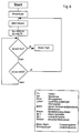
- the basic mode of operation of this electronic control unit 17 can be found in the flow diagram shown in FIG. 4.
- the power steering device according to FIG. 3 can also be equipped with a proximity sensor 18 which scans the position of a suitable component in the steering gear 19. This information from the proximity sensor 18 is in turn fed to the electronic control unit 17, which in a flow chart in FIG. 4 shows this signal evaluates the corresponding manner and determines the supply voltage of the electric motor 18 therefrom.
- the electronic control unit 17 operates as follows from FIG. 4:
- the motor voltage U mot is low, ie the pump 7 works in stand-by mode.
- the signal I passed from the current sensor 15 via the electronic control unit 17 to the switching transistor 16 is compared with a set switch-on limit value Ie and, if the limit value Ie is exceeded, the full motor voltage U mot is switched to the motor 13 or the pump 7.
- This motor voltage U mot remains until a signal I is passed from the current sensor 15 to the electronic control unit 17 which is less than a switch-off limit value Ia. If this switch-off limit value Ia is undershot, the motor voltage U mot is switched back again, so that the pump 7 operates in stand-by mode.
- a minimum time t min is provided to avoid the steering comfort by a quick change between switching on and switching off the full motor voltage U mot .
- the motor voltage U mot is only switched back again after this minimum time t min has been exceeded.
- FIG. 5 The dependence of the motor voltage U mot on the current I through the switching transistor 16 and the load on the pump 7 are shown in FIG. 5. These diagrams show that the full motor voltage U mot is made available as soon as the current signal exceeds the switch-on limit value Ie. The motor voltage U mot is switched back to stand-by mode when the current signal I falls below the switch-off limit Ia for a minimum time t min .
- FIGS. 6, 7 and 8 show an exemplary embodiment for a process control. 6 shows the basic program, while FIGS. 7 and 8 show the flow diagrams for subroutines.
- the motor is first switched to an operating state with low power consumption.
- the minimum current value MW is then detected by sensors and used to calculate a lower and an upper threshold Su, So. It is then checked whether the current motor current exceeds the lower threshold. As long as this is not the case, it is checked whether the motor current falls below the minimum motor current MW determined so far. If so, control returns to the point at which MW is detected. If this is not the case, the routine returns to the point at which it is checked whether the current motor current exceeds the lower threshold Su.
- the test is repeated. If the current rises above the upper limit again within this time interval, the time interval is reset and the upper operating state is maintained. Becomes however, the time interval check ends, the lower operating mode is set and the routine returns to the main routine.
- the routine shown in FIG. 8 it is first determined whether the upper limit So has been exceeded for three seconds. If this is not the case, that is to say if the current motor current returns below this limit within the three seconds, the routine returns to the "motor high" routine according to FIG. 7. However, if the current motor current remains three seconds above the upper threshold So, a current limit is activated which only supplies the motor with a reduced current.
- a sensor evaluation for example the evaluation of a Hall sensor, determines whether the shaft of the electric motor is rotating or whether the motor is blocking. As long as it does this, the motor remains in its state and the current limit remains active. However, if the shaft of the electric motor rotates, this means that the operating conditions have changed so that the pressure has dropped. The current limit is withdrawn again and the routine returns to the "motor high" routine.
Landscapes
- Engineering & Computer Science (AREA)
- Mechanical Engineering (AREA)
- Chemical & Material Sciences (AREA)
- Combustion & Propulsion (AREA)
- Transportation (AREA)
- Computer Hardware Design (AREA)
- General Engineering & Computer Science (AREA)
- Steering Control In Accordance With Driving Conditions (AREA)
- Power Steering Mechanism (AREA)
- Fluid-Pressure Circuits (AREA)
- Control Of Positive-Displacement Pumps (AREA)
Abstract
Claims (21)
- Dispositif de servodirection comprenant une servovalve à centre ouvert pour alimenter un élément de positionnement en pression hydraulique et comprenant une pompe (7) entraînée par un moteur électrique pour alimenter la servovalve en liquide hydraulique, la puissance absorbée du moteur électrique (13) étant modulée par une unité électronique (21) après comparaison entre des paramètres de fonctionnement surveillés par des capteurs et des valeurs de consigne, caractérisé en ce que les capteurs sont connectés à une unité de commande qui comporte au moins un microprocesseur et qui définit les valeurs de consigne en fonction des paramètres de fonctionnement surveillés.
- Dispositif de servodirection selon la revendication 1, caractérisé en ce que l'unité électronique (21) comprend un capteur de courant (15) qui enregistre les besoins en puissance de la pompe (7).
- Dispositif de servodirection selon la revendication 2, caractérisé en ce que l'unité de commande détermine un minimum de consommation de courant par l'intermédiaire du capteur de courant pour définir une valeur de consigne pour commuter entre des plages de puissance absorbée du moteur électrique (13).
- Dispositif de servodirection selon l'une des revendications précédentes, caractérisé en ce que l'unité électronique (21) comprend un capteur de pression qui enregistre les variations de pression au niveau de la servovalve (6).
- Dispositif de servodirection selon l'une des revendications précédentes, caractérisé en ce que l'unité électronique (21) comporte un capteur de proximité (18) qui détecte la position d'un organe du mécanisme de direction (19).
- Dispositif de servodirection selon au moins une des revendications 1 à 5, caractérisé en ce que, lorsque le vérin hydraulique (1) ou la servovalve (6) se trouve en position neutre, le moteur électrique (13) alimenté par une tension minimale tourne en régime d'attente.
- Dispositif de servodirection selon au moins une des revendications 1 à 6, caractérisé en ce que l'unité de commande (17) analyse le signal du capteur (15, 18) et, sur cette base, détermine la puissance absorbée du moteur électrique (13).
- Dispositif de servodirection selon l'une des revendications 1 à 7, caractérisé en ce que l'unité de commande actionne un moyen de limitation de courant pour le moteur électrique (13) si un paramètre de fonctionnement sélectionné excède une valeur limite prédéfinie pendant une durée prédéfinie.
- Dispositif de servodirection selon l'une des revendications 1 à 8, caractérisé en ce que l'unité électronique comporte un capteur de Hall.
- Dispositif de servodirection selon l'une des revendications 1 à 9, caractérisé en ce que l'unité de commande contrôle au moins deux paramètres de fonctionnement dans le cadre d'un contrôle de plausibilité.
- Dispositif de servodirection selon l'une des revendications 1 à 10, caractérisé en ce que l'unité de commande comporte des mémoires pour des programmes d'exécution, des tableaux de valeurs et des valeurs intermédiaires.
- Procédé de commande du moteur électrique d'entraînement de pompe d'un dispositif de servodirection selon au moins une des revendications 1 à 11, caractérisé en ce que les valeurs de consigne auxquelles sont comparés des paramètres de fonctionnement surveillés sont, pour leur part, déterminées en fonction d'au moins un paramètre de fonctionnement surveillé.
- Procédé selon la revendication 12, caractérisé en ce que le paramètre de fonctionnement surveillé est la consommation de courant du moteur électrique.
- Procédé selon l'une des revendications 12 et 13, caractérisé en ce que le paramètre de fonctionnement surveillé est la pression hydraulique.
- Procédé selon l'une des revendications 12 à 14, caractérisé en ce que le paramètre de fonctionnement surveillé est la rotation de l'arbre du moteur électrique.
- Procédé selon l'une des revendications 12 à 15, caractérisé en ce que la consommation de courant minimale est enregistrée à intervalles réguliers et cette valeur sert de base pour calculer la valeur de commutation entre les plages de puissance absorbée du moteur électrique.
- Procédé selon l'une des revendications 12 à 16, caractérisé en ce que l'alimentation en courant du moteur électrique est limitée si au moins un paramètre de fonctionnement sélectionné excède une valeur de consigne supérieure définie pendant un laps de temps prédéfini.
- Procédé selon la revendication 17, caractérisé en ce que la limitation de l'alimentation en courant est choisie pour que le moteur électrique demeure au-dessous d'une limite de régime.
- Procédé selon l'une des revendications 12 à 18, caractérisé en ce que le calcul des valeurs de consigne s'effectue de manière cadencée.
- Procédé selon l'une des revendications 12 à 19, caractérisé en ce que des paramètres de fonctionnement surveillés possédant entre eux un rapport fonctionnel font l'objet d'un contrôle de plausibilité.
- Procédé selon la revendication 20, caractérisé en ce que le contrôle de plausibilité s'effectue à l'aide de tableaux de valeurs mémorisés.
Applications Claiming Priority (3)
| Application Number | Priority Date | Filing Date | Title |
|---|---|---|---|
| DE4335390A DE4335390B4 (de) | 1993-10-16 | 1993-10-16 | Servolenkvorrichtung |
| DE4335390 | 1993-10-16 | ||
| PCT/EP1994/003407 WO1995011152A1 (fr) | 1993-10-16 | 1994-10-16 | Systeme de direction assistee |
Publications (3)
| Publication Number | Publication Date |
|---|---|
| EP0673328A1 EP0673328A1 (fr) | 1995-09-27 |
| EP0673328B1 true EP0673328B1 (fr) | 1997-07-09 |
| EP0673328B2 EP0673328B2 (fr) | 2001-03-14 |
Family
ID=6500360
Family Applications (1)
| Application Number | Title | Priority Date | Filing Date |
|---|---|---|---|
| EP94930178A Expired - Lifetime EP0673328B2 (fr) | 1993-10-16 | 1994-10-16 | Systeme de direction assistee |
Country Status (9)
| Country | Link |
|---|---|
| US (1) | US5761627A (fr) |
| EP (1) | EP0673328B2 (fr) |
| JP (1) | JPH08508222A (fr) |
| KR (1) | KR100332081B1 (fr) |
| BR (1) | BR9405643A (fr) |
| CZ (1) | CZ291355B6 (fr) |
| DE (2) | DE4335390B4 (fr) |
| ES (1) | ES2105771T5 (fr) |
| WO (1) | WO1995011152A1 (fr) |
Cited By (1)
| Publication number | Priority date | Publication date | Assignee | Title |
|---|---|---|---|---|
| US7505840B2 (en) | 2003-06-06 | 2009-03-17 | Trw Automotive Gmbh | Method for controlling an electric pump drive motor of a power steering device |
Families Citing this family (49)
| Publication number | Priority date | Publication date | Assignee | Title |
|---|---|---|---|---|
| DE4418118C1 (de) * | 1994-05-24 | 1995-07-06 | Daimler Benz Ag | Servosteuerung bzw. -lenkung |
| JP3557490B2 (ja) * | 1996-02-20 | 2004-08-25 | 光洋精工株式会社 | パワーステアリング装置 |
| JP3285490B2 (ja) * | 1996-05-28 | 2002-05-27 | 三菱電機株式会社 | 電動式パワーステアリング装置 |
| DE19623567C2 (de) * | 1996-06-13 | 2000-06-08 | Daimler Chrysler Ag | Hydraulische Servosteuerung, insbesondere hydraulische Servolenkung für Kraftfahrzeuge |
| DE19724608B4 (de) * | 1996-06-20 | 2008-10-02 | Volkswagen Ag | Lenkhilfesystem |
| US6025665A (en) * | 1997-02-21 | 2000-02-15 | Emerson Electric Co. | Rotating machine for use in a pressurized fluid system |
| US6078121A (en) | 1997-02-21 | 2000-06-20 | Emerson Electric Co. | Rotor assembly for a rotating machine |
| DE69736296T2 (de) * | 1997-08-13 | 2007-05-31 | Jtekt Corp., Osaka | Servolenkung |
| CZ296715B6 (cs) * | 1997-08-13 | 2006-05-17 | Jtekt Corporation | Posilovac rízení |
| JP3673377B2 (ja) * | 1997-09-26 | 2005-07-20 | 光洋精工株式会社 | パワーステアリング装置 |
| US5967253A (en) * | 1997-10-31 | 1999-10-19 | General Motors Corporation | Electro-hydraulic power steering control with motor speed switching and fluid temperature compensation of standby switch-points |
| US6092618A (en) * | 1997-10-31 | 2000-07-25 | General Motors Corporation | Electro-hydraulic power steering control with fluid temperature and motor speed compensation of power steering load signal |
| DE19818139C2 (de) * | 1998-04-23 | 2001-06-28 | Trw Fahrwerksyst Gmbh & Co | Verfahren zur Begrenzung des hydraulischen Maximaldrucks eines Servolenksystems |
| DE19820381B4 (de) | 1998-05-07 | 2007-01-25 | Trw Fahrwerksysteme Gmbh & Co Kg | Verfahren zur Beeinflussung der Ventilkennlinie |
| JP3648619B2 (ja) * | 1998-05-18 | 2005-05-18 | 光洋精工株式会社 | パワーステアリング装置 |
| US6101435A (en) * | 1998-06-01 | 2000-08-08 | Ford Global Technologies, Inc. | Method for compensating a power assist steering system control signal |
| US6073721A (en) * | 1998-06-01 | 2000-06-13 | Ford Global Technologies, Inc. | Method for limiting hydraulic assist in a power assist steering system |
| JP3668614B2 (ja) * | 1998-07-13 | 2005-07-06 | 光洋精工株式会社 | パワーステアリング装置 |
| JP3652142B2 (ja) | 1998-11-10 | 2005-05-25 | 光洋精工株式会社 | パワーステアリング装置 |
| DE19859319A1 (de) | 1998-12-22 | 2000-06-29 | Eberspaecher J Gmbh & Co | Brennstoffdosierpumpe eines Heizgeräts, insbesondere Wasser- oder Luft-Heizgeräts eines Kraftfahrzeuges, mit Steuergerät |
| US6098741A (en) * | 1999-01-28 | 2000-08-08 | Eaton Corporation | Controlled torque steering system and method |
| USH1846H (en) * | 1999-02-02 | 2000-04-04 | Caterpillar Inc. | Electro-hydraulic steering system for an articulated vehicle |
| US6338016B1 (en) * | 1999-03-08 | 2002-01-08 | Trw Inc. | Method and apparatus for detecting a motor stall condition in an electric assist steering system |
| US6260356B1 (en) | 2000-01-06 | 2001-07-17 | Ford Global Technologies, Inc. | Control method and apparatus for an electro-hydraulic power assisted steering system |
| US6834261B1 (en) | 2000-10-27 | 2004-12-21 | Visteon Corporation | Simulated steering feel system |
| US6557662B1 (en) | 2000-11-22 | 2003-05-06 | Visteon Global Technologies, Inc. | Magneto-rheological simulated steering feel system |
| US6711510B2 (en) | 2001-02-20 | 2004-03-23 | Trw Inc. | Over-current protection method and device |
| JP3868263B2 (ja) * | 2001-10-29 | 2007-01-17 | 株式会社ジェイテクト | パワーステアリング装置 |
| US6845309B2 (en) | 2002-01-30 | 2005-01-18 | Visteon Global Technologies, Inc. | Electric power assist torque check |
| US6647330B1 (en) | 2002-04-30 | 2003-11-11 | Visteon Global Technologies, Inc. | Electronic power assisted steering system and method |
| WO2004061618A2 (fr) * | 2003-01-02 | 2004-07-22 | Electronic Broking Services Limited | Procede et appareil de derivation de points de reference d'instruments commerciaux |
| DE10337954A1 (de) * | 2003-08-19 | 2005-03-17 | Bayerische Motoren Werke Ag | Hilfskraftunterstütztes Lenksystem für ein Kraftfahrzeug, mit hydraulischer offener Mitte |
| WO2006062900A2 (fr) * | 2004-12-06 | 2006-06-15 | Roamware, Inc. | Reacheminement evolutif de messages |
| JP4443457B2 (ja) * | 2005-04-11 | 2010-03-31 | 日立オートモティブシステムズ株式会社 | パワーステアリング装置 |
| US7349793B2 (en) * | 2005-06-16 | 2008-03-25 | Hitachi, Ltd. | Control apparatus for vehicle and method of switching mode of control unit of control apparatus |
| DE102005042509A1 (de) * | 2005-09-07 | 2007-03-22 | Trw Automotive Gmbh | Hydraulische Servolenkvorrichtung und Verfahren zur Steuerung eines Pumpenantriebsmotors |
| US20090133953A1 (en) * | 2007-11-28 | 2009-05-28 | Delphi Technologies, Inc. | Power steering system having a variable-ratio drive mechanism for a vehicle |
| FR2938815B1 (fr) * | 2008-11-25 | 2014-12-26 | Renault Sas | Dispositif de commande pour une direction assistee de vehicule et direction assistee de vehicule integrant un tel dispositif de commande |
| DE102008060306B4 (de) | 2008-12-03 | 2018-12-20 | Trw Automotive Gmbh | Hydraulische Servolenkvorrichtung und Verfahren zur Steuerung eines Pumpenantriebsmotors |
| DE102009000165A1 (de) * | 2009-01-13 | 2010-07-15 | Zf Lenksysteme Gmbh | Verfahren zum Betreiben einer Hilfskraftlenkung |
| FR2944250B1 (fr) * | 2009-04-08 | 2013-01-11 | Renault Sas | Systeme electro-hydraulique d'assistance de direction pour vehicule automobile, et procede de commande associe |
| US8190348B2 (en) * | 2009-06-02 | 2012-05-29 | Honda Motor Co., Ltd. | System and method for damping vibrations in a motor vehicle |
| JP5052640B2 (ja) * | 2010-04-16 | 2012-10-17 | 三菱電機株式会社 | パワーステアリング装置 |
| CN104254693A (zh) * | 2012-03-30 | 2014-12-31 | 鲁卡斯液压有限公司 | 用于运行液压泵设备的方法以及液压泵设备 |
| DE102012104369A1 (de) * | 2012-05-21 | 2013-11-21 | Tedrive Steering Systems Gmbh | Verfahren zur Kompensation des Spiels im Getriebe zwischen Lenkrad und Lenkventil |
| US9302702B1 (en) * | 2015-03-27 | 2016-04-05 | Proterra Inc. | Steering control mechanisms for an electric vehicle |
| DE102015207710B4 (de) * | 2015-04-27 | 2018-09-27 | Continental Automotive Gmbh | Verfahren zur Erhöhung der Genauigkeit einer sensorlosen Druckerfassung |
| US10696327B2 (en) * | 2018-10-26 | 2020-06-30 | Danfoss Power Solutions Inc. | Electronic pressure limiting for dual path systems |
| CN109649482B (zh) * | 2019-01-24 | 2024-05-10 | 安百拓(南京)建筑矿山设备有限公司 | 车辆液压转向系统 |
Family Cites Families (32)
| Publication number | Priority date | Publication date | Assignee | Title |
|---|---|---|---|---|
| DE390862C (de) * | 1921-12-06 | 1924-02-25 | Richard Lepsius Dr | Verfahren zur Aufspeicherung von in Azeton geloestem Azetylen |
| DE2742688A1 (de) * | 1977-09-22 | 1979-04-05 | Zahnradfabrik Friedrichshafen | Hydraulische hilfskraftlenkung mit energieversorgungseinrichtung mit druckspeicher |
| JPS5722967A (en) † | 1980-07-16 | 1982-02-06 | Tokai T R W Kk | Power steering system |
| DE3045428A1 (de) † | 1980-12-02 | 1982-07-01 | Lansing GmbH, 6712 Bobenheim-Roxheim | Lenkeinrichtung fuer flurfoerderzeuge |
| JPS58136560A (ja) † | 1982-02-05 | 1983-08-13 | Tokai T R W Kk | パワ−ステアリング装置 |
| JPS58156457A (ja) † | 1982-03-12 | 1983-09-17 | Nissan Motor Co Ltd | パワ−ステアリング制御装置 |
| US4518055A (en) * | 1982-04-08 | 1985-05-21 | Nissan Motor Company, Limited | Pump-drive device of power-assisted steering system |
| JPS5948267A (ja) † | 1982-09-10 | 1984-03-19 | Mazda Motor Corp | パワ−ステアリング装置のモ−タ制御装置 |
| JPS6018455A (ja) † | 1983-07-09 | 1985-01-30 | Jidosha Kiki Co Ltd | 動力舵取装置の制御方法 |
| JPS6018453A (ja) † | 1983-07-11 | 1985-01-30 | Jidosha Kiki Co Ltd | 動力舵取装置の制御方法 |
| US4557842A (en) * | 1983-08-02 | 1985-12-10 | Joseph Ayers, Inc. | Aluminum soap greases |
| DE3612217A1 (de) * | 1985-04-16 | 1986-11-13 | Abb Ceag Licht- Und Stromversorgungstechnik Gmbh, 59494 Soest | Leuchte |
| DE3622217A1 (de) * | 1986-07-02 | 1988-01-07 | Linde Ag | Lenkeinrichtung mit hydraulischer hilfskraftunterstuetzung fuer ein kraftfahrzeug |
| JP2668235B2 (ja) † | 1988-03-25 | 1997-10-27 | 富士重工業株式会社 | 電動式パワステアリング装置の捩りトルク信号異常検出方法 |
| DE3823413C3 (de) † | 1988-07-11 | 1994-09-01 | Bosch Gmbh Robert | Lenkachsenregelung |
| SE462212B (sv) * | 1988-08-23 | 1990-05-21 | Bahco Hydrauto Ab | Hydrualisk styranordning foer eldrivna fordon |
| US5477675A (en) * | 1989-02-17 | 1995-12-26 | Nartron Corporation | Fluid power assist method and apparatus |
| JPH0350074A (ja) † | 1989-04-22 | 1991-03-04 | Mitsubishi Electric Corp | モータ駆動式パワー・ステアリング装置 |
| DE3920862A1 (de) * | 1989-06-26 | 1991-01-03 | Teves Gmbh Alfred | Hilfskraftlenkung fuer kraftfahrzeuge |
| JP2940958B2 (ja) * | 1989-10-16 | 1999-08-25 | 豊田工機株式会社 | 電気モータを用いた動力舵取装置 |
| DE4040003A1 (de) † | 1990-06-22 | 1992-01-02 | Bosch Gmbh Robert | Servolenkung fuer fahrzeuge |
| US5307892A (en) † | 1990-08-03 | 1994-05-03 | Techco Corporation | Electronically controlled power steering system |
| JP2885903B2 (ja) * | 1990-08-03 | 1999-04-26 | 本田技研工業株式会社 | 車両用流体圧供給装置 |
| JP2896600B2 (ja) † | 1990-10-26 | 1999-05-31 | スズキ株式会社 | 電動パワーステアリング装置 |
| US5224564A (en) † | 1991-05-24 | 1993-07-06 | Ford Motor Company | Hydrostatic power steering system |
| DE4201577A1 (de) † | 1992-01-22 | 1993-07-29 | Bosch Gmbh Robert | Elektronisches steuersystem fuer ein elektromagnetisches stellmittel in einem kraftfahrzeug mit einem steuergeraet |
| DE4207719C2 (de) † | 1992-03-11 | 2002-11-28 | Zahnradfabrik Friedrichshafen | Fremdkraft-Lenkanlage für Kraftfahrzeuge |
| US5267627A (en) * | 1992-03-27 | 1993-12-07 | Imra America, Inc. | Vehicle stability augmentation system |
| DE69324954T2 (de) * | 1992-03-27 | 2000-02-24 | Toyoda Koki K.K., Kariya | Servolenkung |
| DE4227880A1 (de) * | 1992-04-29 | 1993-11-04 | Teves Gmbh Alfred | Hydraulische servolenkung |
| DE4225316C1 (fr) † | 1992-07-31 | 1993-09-09 | Man Nutzfahrzeuge Ag, 80995 Muenchen, De | |
| JP2803487B2 (ja) † | 1992-09-22 | 1998-09-24 | 三菱自動車工業株式会社 | ファジィ制御式電子制御パワーステアリング装置 |
-
1993
- 1993-10-16 DE DE4335390A patent/DE4335390B4/de not_active Expired - Fee Related
-
1994
- 1994-10-16 EP EP94930178A patent/EP0673328B2/fr not_active Expired - Lifetime
- 1994-10-16 CZ CZ19951558A patent/CZ291355B6/cs not_active IP Right Cessation
- 1994-10-16 DE DE59403309T patent/DE59403309D1/de not_active Expired - Fee Related
- 1994-10-16 US US08/481,429 patent/US5761627A/en not_active Expired - Fee Related
- 1994-10-16 KR KR1019950702449A patent/KR100332081B1/ko not_active Expired - Fee Related
- 1994-10-16 JP JP7511309A patent/JPH08508222A/ja active Pending
- 1994-10-16 ES ES94930178T patent/ES2105771T5/es not_active Expired - Lifetime
- 1994-10-16 BR BR9405643-9A patent/BR9405643A/pt not_active IP Right Cessation
- 1994-10-16 WO PCT/EP1994/003407 patent/WO1995011152A1/fr not_active Ceased
Cited By (1)
| Publication number | Priority date | Publication date | Assignee | Title |
|---|---|---|---|---|
| US7505840B2 (en) | 2003-06-06 | 2009-03-17 | Trw Automotive Gmbh | Method for controlling an electric pump drive motor of a power steering device |
Also Published As
| Publication number | Publication date |
|---|---|
| JPH08508222A (ja) | 1996-09-03 |
| KR100332081B1 (ko) | 2002-08-08 |
| US5761627A (en) | 1998-06-02 |
| DE4335390A1 (de) | 1995-04-20 |
| DE59403309D1 (de) | 1997-08-14 |
| EP0673328B2 (fr) | 2001-03-14 |
| BR9405643A (pt) | 1999-09-08 |
| DE4335390B4 (de) | 2007-04-12 |
| KR960702805A (ko) | 1996-05-23 |
| CZ155895A3 (en) | 1996-02-14 |
| EP0673328A1 (fr) | 1995-09-27 |
| CZ291355B6 (cs) | 2003-02-12 |
| ES2105771T3 (es) | 1997-10-16 |
| ES2105771T5 (es) | 2001-09-01 |
| WO1995011152A1 (fr) | 1995-04-27 |
Similar Documents
| Publication | Publication Date | Title |
|---|---|---|
| EP0673328B1 (fr) | Systeme de direction assistee | |
| EP0812754B1 (fr) | Servomécanisme hydraulique , en particulier direction assistée hydraulique pour véhicules à moteur | |
| DE10117059B4 (de) | Fahrzeug, ausgestattet mit einer Lenkungsvorrichtung mit variabler Übersetzung und einer Servolenkung | |
| DE3920862A1 (de) | Hilfskraftlenkung fuer kraftfahrzeuge | |
| EP0983926A2 (fr) | Système de direction pour automobiles non guidées | |
| DE3630612C2 (fr) | ||
| DE102018125049B4 (de) | Hydraulische Lenkanordnung | |
| EP1251059A1 (fr) | Procédé de commande d'un système de direction assistée | |
| DE4418118C1 (de) | Servosteuerung bzw. -lenkung | |
| DE29920122U1 (de) | Elektro-hydraulisches Lenksystem | |
| WO2016078885A1 (fr) | Système de direction pour essieu entraîné d'un véhicule | |
| DE102006004315A1 (de) | Hydraulische Servolenkung | |
| DE102005049223B4 (de) | Hilfskraftlenkungsvorrichtung | |
| EP1631484B1 (fr) | Procede pour commander un moteur d'entrainement de pompe electrique d'un dispositif de direction assistee | |
| EP1695892B1 (fr) | Direction hydraulique active à surveillance simplifiée | |
| EP2499401B1 (fr) | Procédé d'étalonnage et système d'entraînement hydraulique | |
| EP0802314B1 (fr) | Méthode d'ajustement du ralenti d'un moteur à combustion interne, en fonction du braquage | |
| DE19925665B4 (de) | Verfahren zum Einstellen des Systemdrucks in einem hydraulischen Stellantrieb und hydraulischer Stellantrieb | |
| DE102022134056B3 (de) | Hydraulische steuerschaltung für einen hydraulischen motor | |
| DE2446008A1 (de) | Hydrostatisches antriebssystem | |
| DE4021089A1 (de) | Hydraulikeinrichtung fuer nutzfahrzeuge | |
| DE10351769A1 (de) | Lenksystem für ein insbesondere zweispuriges Kraftfahrzeug mit einem Druckspeicher | |
| DE19625778A1 (de) | Verfahren zur lenkbetätigungsabhängigen Einstellung der Leerlaufdrehzahl einer Brennkraftmaschine in einem Kraftfahrzeug | |
| DE10046570C2 (de) | Stellschaltung für ein elektrisch ansteuerbares Ventil | |
| DE102008060306B4 (de) | Hydraulische Servolenkvorrichtung und Verfahren zur Steuerung eines Pumpenantriebsmotors |
Legal Events
| Date | Code | Title | Description |
|---|---|---|---|
| PUAI | Public reference made under article 153(3) epc to a published international application that has entered the european phase |
Free format text: ORIGINAL CODE: 0009012 |
|
| 17P | Request for examination filed |
Effective date: 19950613 |
|
| AK | Designated contracting states |
Kind code of ref document: A1 Designated state(s): DE ES FR GB IT SE |
|
| 17Q | First examination report despatched |
Effective date: 19960916 |
|
| GRAG | Despatch of communication of intention to grant |
Free format text: ORIGINAL CODE: EPIDOS AGRA |
|
| GRAH | Despatch of communication of intention to grant a patent |
Free format text: ORIGINAL CODE: EPIDOS IGRA |
|
| GRAH | Despatch of communication of intention to grant a patent |
Free format text: ORIGINAL CODE: EPIDOS IGRA |
|
| GRAA | (expected) grant |
Free format text: ORIGINAL CODE: 0009210 |
|
| AK | Designated contracting states |
Kind code of ref document: B1 Designated state(s): DE ES FR GB IT SE |
|
| GBT | Gb: translation of ep patent filed (gb section 77(6)(a)/1977) |
Effective date: 19970709 |
|
| REF | Corresponds to: |
Ref document number: 59403309 Country of ref document: DE Date of ref document: 19970814 |
|
| ET | Fr: translation filed | ||
| ITF | It: translation for a ep patent filed | ||
| REG | Reference to a national code |
Ref country code: ES Ref legal event code: FG2A Ref document number: 2105771 Country of ref document: ES Kind code of ref document: T3 |
|
| PLBQ | Unpublished change to opponent data |
Free format text: ORIGINAL CODE: EPIDOS OPPO |
|
| PLBI | Opposition filed |
Free format text: ORIGINAL CODE: 0009260 |
|
| PLBF | Reply of patent proprietor to notice(s) of opposition |
Free format text: ORIGINAL CODE: EPIDOS OBSO |
|
| 26 | Opposition filed |
Opponent name: DAIMLER-BENZ AKTIENGESELLSCHAFT FTP/S, C106 Effective date: 19980408 Opponent name: SACHIO YOSHIDA Effective date: 19980407 Opponent name: ZF FRIEDRICHSHAFEN AG Effective date: 19980408 |
|
| PLBF | Reply of patent proprietor to notice(s) of opposition |
Free format text: ORIGINAL CODE: EPIDOS OBSO |
|
| PLBF | Reply of patent proprietor to notice(s) of opposition |
Free format text: ORIGINAL CODE: EPIDOS OBSO |
|
| PLAB | Opposition data, opponent's data or that of the opponent's representative modified |
Free format text: ORIGINAL CODE: 0009299OPPO |
|
| PLBQ | Unpublished change to opponent data |
Free format text: ORIGINAL CODE: EPIDOS OPPO |
|
| PLAB | Opposition data, opponent's data or that of the opponent's representative modified |
Free format text: ORIGINAL CODE: 0009299OPPO |
|
| R26 | Opposition filed (corrected) |
Opponent name: ZF FRIEDRICHSHAFEN AG * 19980407 SACHIO YOSHIDA * Effective date: 19980408 |
|
| R26 | Opposition filed (corrected) |
Opponent name: ZF LENKSYSTEME GMBH * 19980407 SACHIO YOSHIDA * 19 Effective date: 19980408 |
|
| PLAW | Interlocutory decision in opposition |
Free format text: ORIGINAL CODE: EPIDOS IDOP |
|
| PLAW | Interlocutory decision in opposition |
Free format text: ORIGINAL CODE: EPIDOS IDOP |
|
| PUAH | Patent maintained in amended form |
Free format text: ORIGINAL CODE: 0009272 |
|
| STAA | Information on the status of an ep patent application or granted ep patent |
Free format text: STATUS: PATENT MAINTAINED AS AMENDED |
|
| 27A | Patent maintained in amended form |
Effective date: 20010314 |
|
| AK | Designated contracting states |
Kind code of ref document: B2 Designated state(s): DE ES FR GB IT SE |
|
| GBTA | Gb: translation of amended ep patent filed (gb section 77(6)(b)/1977) | ||
| ET3 | Fr: translation filed ** decision concerning opposition | ||
| ITF | It: translation for a ep patent filed | ||
| REG | Reference to a national code |
Ref country code: ES Ref legal event code: DC2A Kind code of ref document: T5 Effective date: 20010522 |
|
| REG | Reference to a national code |
Ref country code: GB Ref legal event code: IF02 |
|
| PGFP | Annual fee paid to national office [announced via postgrant information from national office to epo] |
Ref country code: GB Payment date: 20040915 Year of fee payment: 11 |
|
| PGFP | Annual fee paid to national office [announced via postgrant information from national office to epo] |
Ref country code: FR Payment date: 20041004 Year of fee payment: 11 |
|
| PGFP | Annual fee paid to national office [announced via postgrant information from national office to epo] |
Ref country code: SE Payment date: 20041005 Year of fee payment: 11 |
|
| PGFP | Annual fee paid to national office [announced via postgrant information from national office to epo] |
Ref country code: ES Payment date: 20041025 Year of fee payment: 11 |
|
| PG25 | Lapsed in a contracting state [announced via postgrant information from national office to epo] |
Ref country code: IT Free format text: LAPSE BECAUSE OF NON-PAYMENT OF DUE FEES;WARNING: LAPSES OF ITALIAN PATENTS WITH EFFECTIVE DATE BEFORE 2007 MAY HAVE OCCURRED AT ANY TIME BEFORE 2007. THE CORRECT EFFECTIVE DATE MAY BE DIFFERENT FROM THE ONE RECORDED. Effective date: 20051016 Ref country code: GB Free format text: LAPSE BECAUSE OF NON-PAYMENT OF DUE FEES Effective date: 20051016 |
|
| PG25 | Lapsed in a contracting state [announced via postgrant information from national office to epo] |
Ref country code: SE Free format text: LAPSE BECAUSE OF NON-PAYMENT OF DUE FEES Effective date: 20051017 Ref country code: ES Free format text: LAPSE BECAUSE OF NON-PAYMENT OF DUE FEES Effective date: 20051017 |
|
| EUG | Se: european patent has lapsed | ||
| GBPC | Gb: european patent ceased through non-payment of renewal fee |
Effective date: 20051016 |
|
| PG25 | Lapsed in a contracting state [announced via postgrant information from national office to epo] |
Ref country code: FR Free format text: LAPSE BECAUSE OF NON-PAYMENT OF DUE FEES Effective date: 20060630 |
|
| REG | Reference to a national code |
Ref country code: FR Ref legal event code: ST Effective date: 20060630 |
|
| REG | Reference to a national code |
Ref country code: ES Ref legal event code: FD2A Effective date: 20051017 |
|
| PGFP | Annual fee paid to national office [announced via postgrant information from national office to epo] |
Ref country code: DE Payment date: 20071031 Year of fee payment: 14 |
|
| PG25 | Lapsed in a contracting state [announced via postgrant information from national office to epo] |
Ref country code: DE Free format text: LAPSE BECAUSE OF NON-PAYMENT OF DUE FEES Effective date: 20090501 |