EP0676325B1 - Ressort avec cran pour système d'actionnement à poignée tournante - Google Patents
Ressort avec cran pour système d'actionnement à poignée tournante Download PDFInfo
- Publication number
- EP0676325B1 EP0676325B1 EP95301444A EP95301444A EP0676325B1 EP 0676325 B1 EP0676325 B1 EP 0676325B1 EP 95301444 A EP95301444 A EP 95301444A EP 95301444 A EP95301444 A EP 95301444A EP 0676325 B1 EP0676325 B1 EP 0676325B1
- Authority
- EP
- European Patent Office
- Prior art keywords
- notch
- spring
- elongate
- detent
- engaging portion
- Prior art date
- Legal status (The legal status is an assumption and is not a legal conclusion. Google has not performed a legal analysis and makes no representation as to the accuracy of the status listed.)
- Expired - Lifetime
Links
- 239000002184 metal Substances 0.000 claims description 10
- 230000005540 biological transmission Effects 0.000 claims 1
- 230000036316 preload Effects 0.000 description 5
- 230000007246 mechanism Effects 0.000 description 4
- 230000009471 action Effects 0.000 description 3
- 230000004888 barrier function Effects 0.000 description 2
- 230000006872 improvement Effects 0.000 description 2
- 229910000639 Spring steel Inorganic materials 0.000 description 1
- 230000009286 beneficial effect Effects 0.000 description 1
- 230000008901 benefit Effects 0.000 description 1
- 230000015572 biosynthetic process Effects 0.000 description 1
- 238000010276 construction Methods 0.000 description 1
- 230000000994 depressogenic effect Effects 0.000 description 1
- 230000000694 effects Effects 0.000 description 1
- 230000003993 interaction Effects 0.000 description 1
- 239000000463 material Substances 0.000 description 1
- 230000013011 mating Effects 0.000 description 1
- 230000004048 modification Effects 0.000 description 1
- 238000012986 modification Methods 0.000 description 1
- 230000000717 retained effect Effects 0.000 description 1
Images


Classifications
-
- B—PERFORMING OPERATIONS; TRANSPORTING
- B62—LAND VEHICLES FOR TRAVELLING OTHERWISE THAN ON RAILS
- B62K—CYCLES; CYCLE FRAMES; CYCLE STEERING DEVICES; RIDER-OPERATED TERMINAL CONTROLS SPECIALLY ADAPTED FOR CYCLES; CYCLE AXLE SUSPENSIONS; CYCLE SIDE-CARS, FORECARS, OR THE LIKE
- B62K23/00—Rider-operated controls specially adapted for cycles, i.e. means for initiating control operations, e.g. levers, grips
- B62K23/02—Rider-operated controls specially adapted for cycles, i.e. means for initiating control operations, e.g. levers, grips hand actuated
- B62K23/04—Twist grips
-
- B—PERFORMING OPERATIONS; TRANSPORTING
- B62—LAND VEHICLES FOR TRAVELLING OTHERWISE THAN ON RAILS
- B62K—CYCLES; CYCLE FRAMES; CYCLE STEERING DEVICES; RIDER-OPERATED TERMINAL CONTROLS SPECIALLY ADAPTED FOR CYCLES; CYCLE AXLE SUSPENSIONS; CYCLE SIDE-CARS, FORECARS, OR THE LIKE
- B62K21/00—Steering devices
- B62K21/26—Handlebar grips
-
- B—PERFORMING OPERATIONS; TRANSPORTING
- B62—LAND VEHICLES FOR TRAVELLING OTHERWISE THAN ON RAILS
- B62M—RIDER PROPULSION OF WHEELED VEHICLES OR SLEDGES; POWERED PROPULSION OF SLEDGES OR SINGLE-TRACK CYCLES; TRANSMISSIONS SPECIALLY ADAPTED FOR SUCH VEHICLES
- B62M25/00—Actuators for gearing speed-change mechanisms specially adapted for cycles
- B62M25/02—Actuators for gearing speed-change mechanisms specially adapted for cycles with mechanical transmitting systems, e.g. cables, levers
- B62M25/04—Actuators for gearing speed-change mechanisms specially adapted for cycles with mechanical transmitting systems, e.g. cables, levers hand actuated
-
- Y—GENERAL TAGGING OF NEW TECHNOLOGICAL DEVELOPMENTS; GENERAL TAGGING OF CROSS-SECTIONAL TECHNOLOGIES SPANNING OVER SEVERAL SECTIONS OF THE IPC; TECHNICAL SUBJECTS COVERED BY FORMER USPC CROSS-REFERENCE ART COLLECTIONS [XRACs] AND DIGESTS
- Y10—TECHNICAL SUBJECTS COVERED BY FORMER USPC
- Y10T—TECHNICAL SUBJECTS COVERED BY FORMER US CLASSIFICATION
- Y10T74/00—Machine element or mechanism
- Y10T74/20—Control lever and linkage systems
- Y10T74/20012—Multiple controlled elements
- Y10T74/20018—Transmission control
- Y10T74/20085—Restriction of shift, gear selection, or gear engagement
- Y10T74/20104—Shift element interlock
- Y10T74/20116—Resiliently biased interlock
-
- Y—GENERAL TAGGING OF NEW TECHNOLOGICAL DEVELOPMENTS; GENERAL TAGGING OF CROSS-SECTIONAL TECHNOLOGIES SPANNING OVER SEVERAL SECTIONS OF THE IPC; TECHNICAL SUBJECTS COVERED BY FORMER USPC CROSS-REFERENCE ART COLLECTIONS [XRACs] AND DIGESTS
- Y10—TECHNICAL SUBJECTS COVERED BY FORMER USPC
- Y10T—TECHNICAL SUBJECTS COVERED BY FORMER US CLASSIFICATION
- Y10T74/00—Machine element or mechanism
- Y10T74/20—Control lever and linkage systems
- Y10T74/20207—Multiple controlling elements for single controlled element
- Y10T74/20256—Steering and controls assemblies
- Y10T74/20268—Reciprocating control elements
- Y10T74/2028—Handle bar type
- Y10T74/20287—Flexible control element
-
- Y—GENERAL TAGGING OF NEW TECHNOLOGICAL DEVELOPMENTS; GENERAL TAGGING OF CROSS-SECTIONAL TECHNOLOGIES SPANNING OVER SEVERAL SECTIONS OF THE IPC; TECHNICAL SUBJECTS COVERED BY FORMER USPC CROSS-REFERENCE ART COLLECTIONS [XRACs] AND DIGESTS
- Y10—TECHNICAL SUBJECTS COVERED BY FORMER USPC
- Y10T—TECHNICAL SUBJECTS COVERED BY FORMER US CLASSIFICATION
- Y10T74/00—Machine element or mechanism
- Y10T74/20—Control lever and linkage systems
- Y10T74/20396—Hand operated
- Y10T74/20474—Rotatable rod, shaft, or post
- Y10T74/20486—Drum and cable
-
- Y—GENERAL TAGGING OF NEW TECHNOLOGICAL DEVELOPMENTS; GENERAL TAGGING OF CROSS-SECTIONAL TECHNOLOGIES SPANNING OVER SEVERAL SECTIONS OF THE IPC; TECHNICAL SUBJECTS COVERED BY FORMER USPC CROSS-REFERENCE ART COLLECTIONS [XRACs] AND DIGESTS
- Y10—TECHNICAL SUBJECTS COVERED BY FORMER USPC
- Y10T—TECHNICAL SUBJECTS COVERED BY FORMER US CLASSIFICATION
- Y10T74/00—Machine element or mechanism
- Y10T74/20—Control lever and linkage systems
- Y10T74/20576—Elements
- Y10T74/20636—Detents
Definitions
- This invention relates to a rotatable grip actuating system for use with a Bowden tube (cable within a tube) type motion translation system. More particularly, it relates to a detent spring for use in a rotatable grip actuating system designed for operating a derailleur gear shifting system on a bicycle.
- the improvement set forth in the co-pending application is in part directed to maximizing the mechanical advantage of a rotatable grip actuating system by minimizing the radius at which the cable is pulled.
- the rotatable grip actuating systems set forth in the above-cited patent and co-pending patent application each have two principal components which are rotatable with respect to each other. Notches are provided in facing circumferential surfaces of the two principal components. These notches cooperate with a spring to establish predetermined positions of the two principal components with respect to each other. The predetermined positions correspond to predetermined shifted positions of the derailleur chain.
- the spring has in the past been formed as a plastic member, but could according to US-A-5 102 372 also be formed of spring metal in an undisclosed manner.
- the prior art plastic spring 200 has feet 202 and 204 located in a spring cavity 206, and an indexing projection 208 engaged in a detent notch 210 in the detent notch circle 212.
- the detent notches 210 have a differential between the angle on the cable release side of the detent notch and on the cable pull side. This differential in angles was provided to substantially balance out the torque required to rotate the grip out of a detent notch, since the cable tension provided by the derailleur mechanism naturally pulls the rotational grip in the direction of cable release.
- the torque required to release a detent 208 is a function of the spring preload, contact angles and the stiffness of the leaf portions 214 of the plastic spring. If the preload force of the spring is significantly reduced, the release torque is also significantly reduced.
- the leaf portions 214 of the plastic spring 200 are supported, when the detent 208 is in a notch 210, by a pair of feet 216 which engage a correspondingly located pair of projections 218 in the cavity 206.
- This embodiment was intended to maintain the preload force on the spring when the detent 208 was in a notch 210.
- a rotatable handgrip bicycle gear shifter of the kind referred to, i.e. according to the preamble of claim 1, having the characterising features of claim 1.
- the detent spring is made of a spring type metal and formed with an elongate base having first and second ends, and with an arm extending from the first end, which extends over the elongate base.
- the free end of the arm can be bent to provide a notch engaging portion or detent having an apex which extends in a direction away from the base.
- a first rotatable member has a surface, which can be cylindrical, in which is formed an elongate notch for retaining the base of the detent spring.
- a second member with respect to which the first member is rotatable has a second surface, which can be generally cylindrical located radially outward from the first surface.
- a series of space notches are formed in the second surface which are engaged by the detent or notch engaging portion of the spring as the first member is rotated with respect to the second member.
- the elongate base member of the spring is curved, such that only the first and second ends engage the base of the elongate notch.
- the first and second ends are formed as curved portions with the centre of the curve of each curved portion located on the opposite side of the elongate base member as the centre of the curve of the base member.
- a rotatable grip actuating system 10 is placed over a handlebar 12.
- the portion of the handlebar 14 shown projecting to the right in FIG. 3, is connected to the bicycle handlebar stem (not shown).
- the handlebar 12 also projects to the left of the system 10 as shown in FIG. 3 to support the customary handgrip normally place at the end of the handlebar.
- the system 10 has two principal components, a housing 16 secured to the handlebar 12 and a rotatable grip 18.
- the housing 16 includes an elongate tube or mandrel 20 which is received in a snug fit over the handlebar 12.
- the housing 16 is formed with a pocket (not shown) on the right side as viewed in FIG. 3 for receiving a U-shaped clamp 22 which secures the housing 16 to the handlebar 12.
- the clamp 22 is secured to the handlebar by a bolt 24 which loosely passes through a hole 26 in one leg of the clamp and engages threads in a hole 28 provided in the other leg of the clamp.
- a cable guide tube 30 Formed as a portion of the housing 16 is a cable guide tube 30.
- the guide tube 30 is provided at its distal end with external threads 32 for mating with internal threads provided on a coupler 34.
- the coupler 34 secures a cable tube 36 to the cable guide tube 30.
- a spring retaining portion 40 Surrounding the mandrel 20, next to a radially extending wall 38 of the housing 16 is a spring retaining portion 40.
- notch 42 Formed in a generally cylindrical surface of the spring retaining portion 40 is an elongate notch 42 which captures a first portion 44 of a formed spring 46, a second portion of which formed spring cooperates with the rotatable grip 18 to define selected positions of the rotatable grip 18.
- First portion 44 of spring 46 rests in the notch 42, while a convex bend or detent 48 in the second portion of the spring is engageable in notches 50, 52 and 54 formed on the inner generally cylindrical or circumferential surface of wall 56 of the rotatable grip 18.
- the interaction of the detent 48 of spring 46 with the notches 50, 52 and 54 define positions of the rotatable grip 18 with respect to the housing 16 which correspond to desired engagement positions of the derailleur shifting mechanism.
- the rotatable grip 18 is formed with an external grip portion 58 and an adjoining enlarged portion 60 on which may be printed numerals, shown as 1, 2 and 3 in FIG. 3, which when located with respect to an index mark 62 on the housing 10 define three operating positions of the handgrip assembly. Extending to the left of the grip portion 58, as viewed in FIG. 4, is not only the wall 56, but also a cable retaining and engaging portion 64 of rotatable grip 18. An operating cable 66 is retained behind a radially extending wall portion 68 of portion 64 and a radial extending face 70 of the enlarged portion 60. The operating cable rests upon a spool 72 of variable radius formed between the wall portion 68 and the radially extending face 70.
- the radius at which rotation of the rotatable grip 18 acts on the operating cable 66 is referred to as the spooling radius.
- a slot having a variable radial height is formed between the wall portion 68 and radially extending face 70 to form the spool 72.
- the radial height of the slot at end 74 of the slot is just slightly larger than the diameter of the cable 66.
- a retainer 76 is secured to the end of the cable to prevent it from being pulled through the slot.
- the spool 72 having dropped away at 78, where the cable 66 exits from the slot, the radial height of the slot is considerably higher than the diameter of the cable. While the cable is shown engaging the radially outward surface of the slot in FIG. 4, when the system is assembled and tension applied to the cable, it rests on the radially inward surface or spool 72 as shown in FIGS. 5 and 6.
- the grip With the cable 66 secured in the slot formed in the grip portion 18, and first portion of spring 44 placed in the elongate notch 42, the grip is assembled to the housing 16 in the directions of the arrow such that the wall 56 is received in a space 80 between an outer wall 82 of the housing 16 and the spring retaining portion 40.
- a cover 84 is placed over the open portion of the cable guide tube 30 and secured in place by a screw 86 which is threadedly engaged in a hole 88 formed in a projection 90 extending from the housing 16.
- the detent spring assembly portion of the rotatable grip actuating system includes an inward facing generally cylindrical wall 48 in which are formed notches 50, 52 and 54.
- the number of notches corresponds to the number of positions required for actuation of the derailleur shifting system.
- One portion of the rotatable grip actuating system includes the mandrel 20 and a spring retaining member having an outwardly facing generally cylindrical surface in which is formed a spring retaining elongate notch 42.
- spring 46 is formed with a first portion in the form of an elongate base member 44, the first and second ends of which 92 and 94 respectively are formed in a generally semicircular shape.
- An arm 96 extends from the first end 92 of the spring 46, and cantilevers over the elongate base 44 to give the spring an overall narrow U-shape.
- a notch engaging outwardly convex with respect to the base portion 44, bent portion or detent 48. The free end of the arm 96 is bent inwardly toward the first or base member 44.
- the base member 44 of the spring 46 is curved to correspond to the curvature of the base of the elongate notch 42.
- the ends 100 and 102 of elongate notch 42 are spaced apart at a greater distance than the distance between the extremities of the curved portions 92 and 94 of the spring.
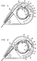
- the force required to move it in and out of one of the notches or detents 50, 52 or 54, which are symmetrical about their apex, depends on the direction of rotation. Particularly, less force is required to effectively displace the spring 46 in the direction of the arrow B, in FIG. 6, wherein sloping edge 104 of the detent 48 is engaged by the sloping portion of one of the notches 50, 52 or 54.
- a cantilever loading is applied to flex the arm 96 and urge the notch-engaging portion 48 out of engagement with each spaced notch 50, 52, 54 when the rotatable grip 18 is moved relative to the housing 16 in a direction from the first end 92 of the base portion 44 toward the second end 94, as depicted in FIG. 6.
- less force is required to depress the detent 48, and therefore the arm 96, as the detent 48 moves out of a notch.
- a column loading is applied to flex the arm 96 and urge the notch-engaging portion 48 out of engagement with each notch 50, 52, 54 when the rotatable grip 18 is moved relative to the housing 16 in the opposite direction.
- the spring 46 thus offers greater resistance to rotation in the direction A as shown in FIG. 5.
- the engagement of the side of the detent 48 which continues as extension 98 abuts a sloping edge of a notch 50, 52 or 54 to first applying a force through the arm 96 and the bend 92 to the end 100 of the notch. While the detent 48 will eventually be depressed as it moves out of the notch or detent due to continued rotation of the rotatable grip 18, a greater force is required to do so than for rotation in the direction of arrow B.
- the notches 50, 52 and 54 can be made symmetrical while at the same time providing different degrees of resistance for rotation in opposite directions, thereby equalizing the force of the return spring in the derailleur shifting mechanism. That is, and neglecting for a moment the effects of the tension of the derailleur cable 66, when the notch-engaging portion or detent 48 is in a detent position, such as notch 52 as shown in FIG. 6, the user must apply more torque to the rotatable grip 18 to force the detent 48 out of the notch 52 in the cable-releasing direction (i.e., counterclockwise in FIG. 6) than is needed to force the detent 48 out of the notch 52 in the cable-pulling direction (i.e., clockwise in FIG. 6).
- This difference in required torque may be used to compensate for the load applied on the derailleur cable 66 by the derailleur spring (not shown).
- the torque that must be applied to the grip 18 to pull the derailleur cable 66 is made to be similar to or the same as the torque required to be applied to the grip 18 to release the derailleur cable 66. It therefore will be as easy for the user to down-shift as it is to up-shift.
- the spring 46 can be readily designed to operate within its elastic range at all times.
- the stiffness of the spring can be determined, for instance by varying the thickness of the spring leaf, a spring can be designed which will have a high contact force with the surface between notches when compressed, but a relatively low preload when residing in the notches 50, 52 and 54.
- the spring may be designed such that the rotatable grip 18 rotates freely in the cable release direction until the detent 48 of the spring meets the front wall of notches 50, 52 or 54, which is the desired cable position for a particular sprocket position.
- the curvature of the notch as it merges into the circumferential surface between the notches may have a larger radius, so as to cause less wear on both the detent 48 and the notches and the surfaces of the wall 56 engaged thereby.
- the torque required for rotating from one predetermined position to another can in part be defined by the angle which the sides of the notches 50, 52 and 54 make with the radius of the wall 56 extending between the notches.
- the spring 106 is similar to the spring 46 shown in FIG. 4 - 7, in that the first end of the spring 106 is curved and is provided with an arm 108. Further, a convex bend or detent 110 and extension 112 are formed at the free end of arm 108. The second end 114 of the spring 106 is formed with a radially extending portion 116.
- the spring retaining member 40 is provided with a circumferentially extending portion or barrier 118 located radially outward and extending over the elongate notch 42 and the free end 120 of the radially extending portion 116 of the spring.
- the second end of the spring 114 is prevented from lifting by the engagement of free end 120 with the barrier 118.
- the spring 46 is formed of cylindrical wire.
- the force applied by the spring as it moves into and out of the notches 50, 52 and 54 may be determined by selecting the characteristics of the spring wire including its diameter resilience, etc., and the formation of the spring, including the number of spirals of spring the length of the arm, etc.
- the spring is formed from a single piece of cylindrical spring steel stock. The first end 130 of the spring is formed as a pair of helixes.
- each helix extends as an arm 132 at the ends of which is formed a generally rectangular portion 134.
- Side 136 of the rectangular portion 134 forms a detent 136 which engages the notches 50, 52, and 54 and the cylindrical surface therebetween.
- the outer ends of the helixes are formed with arcuate extensions 138 and 140 which form the base of the spring. Bent portions 142 and 144 are formed at the free ends of the arcuate extension to provide radial extensions similar to that of the embodiment shown in FIG. 8 and 9.
Landscapes
- Engineering & Computer Science (AREA)
- Mechanical Engineering (AREA)
- Chemical & Material Sciences (AREA)
- Combustion & Propulsion (AREA)
- Transportation (AREA)
- Mechanical Control Devices (AREA)
- Springs (AREA)
- Transmission Devices (AREA)
- Steering Devices For Bicycles And Motorcycles (AREA)
Claims (10)
- Sélecteur de vitesse (10) à poignée tournante pour bicyclette, destiné à être monté sur un guidon de bicyclette (12), le sélecteur (10) tirant ou libérant de façon linéaire un câble de commande tendu (66) jusqu'à l'une quelconque d'une pluralité de positions prédéterminées, chacune des positions provoquant la mise en prise d'une vitesse respective d'une transmission par chaîne de bicyclette, le sélecteur (10) comportant des premier et second éléments (16, 18) montés en relation coaxiale l'un avec l'autre, l'un (18) des premier et second éléments (16, 18) étant mobile en rotation par rapport à l'autre (16) dans chacune de deux directions angulaires opposées afin de définir des emplacements prédéterminés l'un par rapport à l'autre, lesquels emplacements correspondent auxdites positions du câble de commande, chaque élément (16, 18) comportant une surface faisant face à l'autre des éléments (16, 18),
la surface du premier élément (16) comportant une encoche allongée (42) formée dans celle-ci afin de retenir un ressort à cran de détente (46, 106) fait de métal à ressort, l'encoche allongée (42) comportant une base allongée et des parois latérales (100, 102) aux extrémités de la base allongée s'étendant généralement en direction du second élément (18), la surface du second élément (18) présentant une série d'encoches espacées (50, 52, 54) formées dans celles-ci, caractérisée en ce que
Le ressort (46, 106) comprendun élément de base allongée (44 ; 138, 140) présentant des premières (92, 130) et secondes (94, 114) extrémités, l'élément de base allongée (44 ; 138, 140) étant disposé dans l'encoche (42),un bras (96, 108, 132) s'étendant à partir de la première extrémité (92) de l'élément de base allongée (44 ; 138, 140), le bras (96, 108, 132) ayant une extrémité libre (98, 112) et s'étendant au-dessus de l'élément de base allongée (44 ; 138, 140) de façon à pouvoir être déplacé radialement par rapport à l'élément de base allongée (44 ; 138, 140), etune partie d'enclenchement avec une encoche (48, 110, 136) formée à proximité de l'extrémité libre (98, 112), grâce à quoi la partie d'enclenchement avec une encoche (48, 110, 136) est en contact avec la surface du second élément (18) lorsque l'on déplace l'un des premier (16) et second (18) éléments par rapport à l'autre, et vient s'enclencher dans l'une des encoches (50, 52, 54) lorsqu'on l'amène en alignement avec celle-ci. - Sélecteur de vitesse à poignée tournante pour bicyclette selon la revendication 1, dans lequel le premier élément (16) est formé avec une partie de retenue (118) espacée de la base allongée de l'encoche allongée (42) et recouvrant celle-ci, et le ressort (42) est formé avec une patte s'étendant à partir de la seconde extrémité (94, 114) en direction de la partie de retenue (118), la patte comportant une extrémité libre (120) qui vient en contact avec la partie de retenue (118) afin de maintenir la seconde extrémité (94, 114) de la base allongée du ressort à proximité immédiate de la base allongée de l'encoche (42).
- Sélecteur de vitesse à poignée tournante pour bicyclette selon la revendication 1 ou la revendication 2, dans lequel l'élément de base allongée (44) est incurvé, de sorte que seules lesdites première et seconde extrémités viennent en contact avec la base de ladite encoche allongée.
- Sélecteur de vitesse à poignée tournante pour bicyclette selon la revendication 3, dans lequel les première (92) et seconde (94) extrémités dudit élément de base allongée (44) sont formées en parties recourbées, le centre de courbure de chaque partie recourbée étant situé du côté dudit élément de base allongée qui est opposé au centre de courbure dudit élément de base.
- Sélecteur de vitesse à poignée tournante pour bicyclette selon l'une quelconque des revendications précédentes, dans lequel ladite partie d'enclenchement avec une encoche (48, 110) est formée avec une surface incurvée qui peut s'enclencher dans lesdites encoches (50, 52, 54).
- Sélecteur de vitesse à poignée tournante pour bicyclettte selon l'une quelconque des revendications précédentes, dans lequel, lorsque le mouvement relatif des premier (16) et second (18) éléments l'un par rapport à l'autre est tel que quand la surface dudit second élément comportant la série d'encoches espacées dans celle-ci se déplace par rapport à la surface dudit premier élément comportant l'encoche allongée dans celle-ci, dans la direction dans laquelle le bras s'étend au-dessus dudit élément de base allongée (44), moins de force est nécessaire pour dégager ladite partie d'enclenchement avec une encoche (48, 110) d'une encoche enclenchée que lorsque l'on déplace les premier et second éléments dans la direction opposée l'un par rapport à l'autre.
- Sélecteur de vitesse à poignée tournante pour bicyclette selon l'une quelconque des revendications précédentes, dans lequel ledit ressort à cran de détente est formé à partir d'une bande plate allongée de métal à ressort.
- Sélecteur de vitesse à poignée tournante pour bicyclette selon l'une quelconque des revendications 1 à 6, dans lequel ledit ressort à cran de détente est formé à partir d'une longueur de fil métallique pour ressort.
- Sélecteur de vitesse à poignée tournante pour bicyclette selon l'une quelconque des revendications précédentes, dans lequel les parois latérales de l'encoche allongée (42) sont écartées d'une distance supérieure à la longueur totale du ressort à cran de détente (46, 106) afin de permettre le déplacement du ressort à cran de détente à l'intérieur de l'encoche allongée.
- Sélecteur de vitesse à poignée tournante pour bicyclette selon l'une quelconque des revendications précédentes, dans lequel la partie d'enclenchement avec une encoche (48, 110) est disposée sur le bras (96, 108) de façon qu'un effort en porte-à-faux soit appliqué pour faire fléchir le bras et pousser la partie d'enclenchement avec une encoche, hors d'enclenchement avec l'une des encoches espacées (50, 52, 54) lorsque l'on dépace le second élément par rapport au premier élément dans une direction allant de la première extrémité de la partie de base en direction de la seconde extrémité, et qu'un effort de flambage soit appliqué pour faire fléchir le bras et pousser la partie d'enclenchement avec une encoche hors d'enclenchement avec l'encoche espacée lorsque l'on déplace le second élément par rapport au premier élément dans une direction opposée, l'effort de flambage nécessaire pour pousser la partie d'enclenchement avec une encoche hors d'enclenchement avec l'encoche espacée étant plus important que l'effort en porte-à-faux nécessaire pour pousser la partie d'enclenchement avec une encoche hors d'enclenchement avec l'encoche espacée.
Applications Claiming Priority (4)
| Application Number | Priority Date | Filing Date | Title |
|---|---|---|---|
| US295370 | 1970-01-14 | ||
| US08/207,249 US5476019A (en) | 1994-03-07 | 1994-03-07 | Rotatable handgrip actuating system |
| US08/295,370 US5524501A (en) | 1994-03-07 | 1994-08-24 | Detent spring for rotatable grip actuating system |
| US207249 | 1998-12-09 |
Publications (3)
| Publication Number | Publication Date |
|---|---|
| EP0676325A2 EP0676325A2 (fr) | 1995-10-11 |
| EP0676325A3 EP0676325A3 (fr) | 1996-02-07 |
| EP0676325B1 true EP0676325B1 (fr) | 1997-08-06 |
Family
ID=26902083
Family Applications (1)
| Application Number | Title | Priority Date | Filing Date |
|---|---|---|---|
| EP95301444A Expired - Lifetime EP0676325B1 (fr) | 1994-03-07 | 1995-03-06 | Ressort avec cran pour système d'actionnement à poignée tournante |
Country Status (6)
| Country | Link |
|---|---|
| US (1) | US5662000A (fr) |
| EP (1) | EP0676325B1 (fr) |
| JP (1) | JPH0844450A (fr) |
| CN (1) | CN1111584A (fr) |
| DE (2) | DE676325T1 (fr) |
| ES (1) | ES2087053T3 (fr) |
Families Citing this family (31)
| Publication number | Priority date | Publication date | Assignee | Title |
|---|---|---|---|---|
| DE4442952C1 (de) * | 1994-12-02 | 1996-02-22 | Fichtel & Sachs Ag | Schalter für Getriebe an Fahrrädern |
| DE19546621A1 (de) * | 1995-12-14 | 1997-06-19 | Fichtel & Sachs Ag | Drehgriffschalter für Fahrräder |
| DE19613575A1 (de) | 1996-04-04 | 1997-10-09 | Fichtel & Sachs Ag | Rastenschalter für ein Fahrradgetriebe |
| US5921140A (en) * | 1996-04-04 | 1999-07-13 | Fichtel & Sachs Ag | Index shifter for a bicycle transmission and a method of making an index shifter for a bicycle transmission |
| DE19700885A1 (de) | 1997-01-14 | 1998-07-16 | Sram De Gmbh | Rastenschalter für ein Fahrradgetriebe |
| DE19734682B4 (de) * | 1997-08-11 | 2008-04-10 | Sram Deutschland Gmbh | Rastenschalter, insbesondere Drehgriffschalter zur Steuerung eines Fahrradgetriebes |
| DE19734685A1 (de) * | 1997-08-11 | 1999-02-18 | Sram De Gmbh | Rastenschalter, insbesondere Drehgriffschalter zur Steuerung eines Fahrradgetriebes |
| DE19734683A1 (de) * | 1997-08-11 | 1999-02-18 | Sram De Gmbh | Betätigungseinrichtung für Fahrradgetriebe |
| DE19753901A1 (de) * | 1997-12-05 | 1999-06-10 | Sram De Gmbh | Schalter für ein Fahrradgetriebe |
| US6067875A (en) * | 1998-06-12 | 2000-05-30 | Ritchey Designs, Inc. | Handlebar-mounted bicycle shifter system and method |
| US6755265B2 (en) * | 1999-02-05 | 2004-06-29 | Mattel, Inc. | Children's ride-on vehicle |
| US6389920B1 (en) * | 1999-03-09 | 2002-05-21 | AD II Engineering Inc. | Mechanism for easy and precise control of gear shifting device of bicycle |
| DE19922328A1 (de) | 1999-05-14 | 2000-11-16 | Sram De Gmbh | Seilführung in einem Schalter für Fahrradgetriebe |
| AU2000242753B2 (en) * | 2000-04-18 | 2004-09-30 | Zamtec Limited | Ink jet ejector |
| US6595894B2 (en) | 2001-03-09 | 2003-07-22 | Shimano (Singapore) Private Limited | Shift control device |
| US20030166427A1 (en) * | 2002-03-01 | 2003-09-04 | Dillon Tom W. | Indexed cycle derailleur |
| US7104154B2 (en) * | 2003-05-29 | 2006-09-12 | Shimano Inc. | Bicycle shift control device |
| US7013751B2 (en) * | 2003-05-29 | 2006-03-21 | Shimano Inc. | Bicycle shift control device |
| CN1323894C (zh) * | 2003-06-25 | 2007-07-04 | 日驰企业股份有限公司 | 双棘爪变速装置 |
| US20060053936A1 (en) * | 2004-08-17 | 2006-03-16 | Wancket Daniel V | Variable ratio hand twist throttle cable pulley |
| US20060180153A1 (en) * | 2005-01-27 | 2006-08-17 | Bernie Schaub | Assembly for mounting a device to a mask |
| US20070068312A1 (en) * | 2005-09-07 | 2007-03-29 | Shimano Inc. | Bicycle shift control mechanism |
| JP2007076545A (ja) * | 2005-09-15 | 2007-03-29 | Shimano Inc | 自転車用変速操作装置 |
| DE102006011855A1 (de) * | 2006-03-15 | 2007-09-20 | Sram Deutschland Gmbh | Schaltermechanismus mit Kompressionsfeder |
| US20090229388A1 (en) * | 2008-03-17 | 2009-09-17 | Lee Jeongyeop | Cable connecting apparatus of controller for air conditoner in vehicle |
| DE102011014234A1 (de) * | 2011-03-15 | 2012-09-20 | Keiper Gmbh & Co. Kg | Rastschalter und Fahrzeugsitz |
| US9377100B2 (en) * | 2012-07-06 | 2016-06-28 | Kongsberg Automotive Ab | Shifter assembly |
| DE202013002492U1 (de) * | 2013-03-15 | 2014-06-17 | Rti Sports Vertrieb Von Sportartikeln Gmbh | Fahrradgriff-System |
| US9731787B2 (en) * | 2013-06-28 | 2017-08-15 | Shimano Inc. | Bicycle operating device mounting assembly |
| DE102019135070A1 (de) * | 2019-12-19 | 2021-06-24 | Grammer Aktiengesellschaft | Bedienelement |
| US12454330B2 (en) * | 2023-06-19 | 2025-10-28 | Shimano Inc. | Operating device for human-powered vehicle |
Family Cites Families (41)
| Publication number | Priority date | Publication date | Assignee | Title |
|---|---|---|---|---|
| US1231055A (en) * | 1917-01-18 | 1917-06-26 | Raymond P Packard | Controlling mechanism. |
| US2153430A (en) * | 1937-11-20 | 1939-04-04 | Mallory & Co Inc P R | Switch index mechanism |
| US2626335A (en) * | 1950-10-18 | 1953-01-20 | Hart Mfg Co | Electric switch |
| US3020778A (en) * | 1954-08-05 | 1962-02-13 | Frithjof C Davidson | Bicycle gear shift control |
| GB1004357A (en) * | 1961-12-02 | 1965-09-15 | Sturmey Archer Gears Ltd | Improvements in or relating to twist-grip controls |
| US3489029A (en) * | 1967-03-17 | 1970-01-13 | Oak Electro Netics Corp | Detent spring |
| US3522745A (en) * | 1967-06-22 | 1970-08-04 | Tomos Motor Vehicles Factory | Gas control turning grip for motors with internal combustion |
| CH537865A (de) * | 1971-07-21 | 1973-06-15 | Karlsruhe Augsburg Iweka | Changiervorrichtung |
| FR2210973A5 (fr) * | 1972-12-20 | 1974-07-12 | Juy Lucien | |
| JPS522224B2 (fr) * | 1973-06-19 | 1977-01-20 | ||
| JPS5715543Y2 (fr) * | 1975-08-20 | 1982-03-31 | ||
| US4201095A (en) * | 1975-08-25 | 1980-05-06 | Jack Myles | Semi-automatic gearshift for dual derailleur bicycle |
| US4055093A (en) * | 1976-06-18 | 1977-10-25 | Amf Incorporated | 10-Speed bicycles |
| US4191065A (en) * | 1978-02-07 | 1980-03-04 | Beugelsdyk Anthony F | Throttle twist grip |
| JPS54118039A (en) * | 1978-03-04 | 1979-09-13 | Maeda Ind | Operating lever for bicycle |
| GB2024381B (en) * | 1978-06-15 | 1982-06-23 | Ti Raleigh Ind Ltd | Twist grip controls |
| FR2446513A1 (fr) * | 1979-01-12 | 1980-08-08 | Anvar | Dispositif selecteur, notamment pour derailleur de bicyclette, et derailleur equipe d'un tel dispositif |
| JPS5631519U (fr) * | 1979-08-18 | 1981-03-27 | ||
| JPS5849585A (ja) * | 1981-09-19 | 1983-03-23 | 本田技研工業株式会社 | 二輪自動車用チョ−クレバ−装置 |
| US4548092A (en) * | 1983-02-10 | 1985-10-22 | Strong Jr Samuel Z | Bicycle gear shift unit |
| DE3317382C2 (de) * | 1983-05-13 | 1986-09-11 | Bayerische Motoren Werke AG, 8000 München | Verbindung zweier, von einer Seele durchsetzter Bowdenzughüllen |
| CH667244A5 (en) * | 1985-08-29 | 1988-09-30 | Pefag Ag | Twist-grip gearchange for bicycle - has clamp for Bowden cable and ratchet location of gears |
| US4793821A (en) * | 1986-01-17 | 1988-12-27 | Engineered Transitions Company, Inc. | Vibration resistant electrical coupling |
| DE3719421A1 (de) * | 1987-06-11 | 1988-12-22 | Unseld Hans Peter Dr | Kombinierter brems- und gangschaltungsdrehgriff |
| US4900291B1 (en) * | 1988-01-06 | 2000-04-25 | Sram Corp | Bicycle gear shifting method and apparatus |
| US4938733A (en) * | 1988-01-06 | 1990-07-03 | Sram Corporation | Bicycle gear shifting method and apparatus |
| US5134897A (en) * | 1989-10-20 | 1992-08-04 | Campagnolo S.R.L. | Twist-grip device for operating the gears of a bicycle |
| DE3938454A1 (de) * | 1989-11-18 | 1991-05-23 | Dietrich Gerhard Ellsaesser | Fahrradschalteinheit mit elektrohydraulischer ansteuerung |
| US5186071A (en) * | 1990-03-09 | 1993-02-16 | Maeda Industries, Ltd. | Bicycle speed change lever assembly |
| JP2581996B2 (ja) * | 1990-12-18 | 1997-02-19 | ブリヂストンサイクル株式会社 | 自転車のグリップ式変速操作装置 |
| JPH04260889A (ja) * | 1991-02-13 | 1992-09-16 | Maeda Kogyo Kk | 自転車用変速操作装置 |
| US5197927B1 (en) * | 1991-03-20 | 2000-10-17 | Sram Corp | Bicycle derailleur cable actuating system |
| US5102372A (en) * | 1991-03-20 | 1992-04-07 | Sram Corporation | Bicycle derailleur cable actuating system |
| JPH04125996U (ja) * | 1991-05-01 | 1992-11-17 | マエダ工業株式会社 | 自転車用変速操作レバー装置 |
| DE4128866A1 (de) * | 1991-08-30 | 1993-03-04 | Fichtel & Sachs Ag | Elektromechanische gangschaltung fuer fahrraeder |
| JPH05270475A (ja) * | 1992-03-23 | 1993-10-19 | Maeda Kogyo Kk | 自転車用変速操作装置 |
| DE4212320A1 (de) * | 1992-04-13 | 1993-10-14 | Fichtel & Sachs Ag | Elektrische Stellvorrichtung |
| DE4212319A1 (de) * | 1992-04-13 | 1993-10-14 | Fichtel & Sachs Ag | Steuervorrichtung |
| US5261858A (en) * | 1992-06-19 | 1993-11-16 | Browning Automatic Transmission | Method and system for computer-controlled bicycle gear shifting |
| JPH0648366A (ja) * | 1992-07-28 | 1994-02-22 | Maeda Kogyo Kk | 自転車用変速操作装置 |
| US5241877A (en) * | 1992-12-04 | 1993-09-07 | Chen Chun Hsung | Gear selector |
-
1994
- 1994-12-29 JP JP6341054A patent/JPH0844450A/ja active Pending
-
1995
- 1995-02-25 CN CN95101854A patent/CN1111584A/zh active Pending
- 1995-03-06 EP EP95301444A patent/EP0676325B1/fr not_active Expired - Lifetime
- 1995-03-06 DE DE0676325T patent/DE676325T1/de active Pending
- 1995-03-06 DE DE69500508T patent/DE69500508T2/de not_active Expired - Fee Related
- 1995-03-06 ES ES95301444T patent/ES2087053T3/es not_active Expired - Lifetime
-
1996
- 1996-03-01 US US08/609,676 patent/US5662000A/en not_active Expired - Lifetime
Also Published As
| Publication number | Publication date |
|---|---|
| EP0676325A2 (fr) | 1995-10-11 |
| DE69500508T2 (de) | 1997-12-04 |
| ES2087053T1 (es) | 1996-07-16 |
| DE69500508D1 (de) | 1997-09-11 |
| US5662000A (en) | 1997-09-02 |
| CN1111584A (zh) | 1995-11-15 |
| EP0676325A3 (fr) | 1996-02-07 |
| DE676325T1 (de) | 1996-06-27 |
| JPH0844450A (ja) | 1996-02-16 |
| ES2087053T3 (es) | 1997-12-01 |
Similar Documents
| Publication | Publication Date | Title |
|---|---|---|
| EP0676325B1 (fr) | Ressort avec cran pour système d'actionnement à poignée tournante | |
| US5524501A (en) | Detent spring for rotatable grip actuating system | |
| EP0790175B1 (fr) | Manette de changement de vitesse pour bicyclette entourant le guidon | |
| EP1232940B1 (fr) | Dispositif de changement de vitesse pour bicyclette | |
| EP1553017B1 (fr) | Bouton type de dispositif de commande de changement de vitesses pour bicyclette | |
| US5921140A (en) | Index shifter for a bicycle transmission and a method of making an index shifter for a bicycle transmission | |
| EP1238899B1 (fr) | Dispositif de commande pour dérailleur | |
| EP0628448B1 (fr) | Serrure mécanique linéaire de précision | |
| EP0091324B1 (fr) | Dispositif de contrôle de changement de vitesse pour bicyclette | |
| EP0810150A2 (fr) | Dispositif de commande de changement de vitesses pour bicyclette | |
| US5588925A (en) | Shifter for transmissions on bicycles | |
| US20010042421A1 (en) | Bicycle speed control apparatus | |
| US6644143B2 (en) | Grip gear-shifter for actuating derailleur of bicycle | |
| GB2169065A (en) | Indexing mechanisms and controls embodying the same | |
| US5666859A (en) | Latching shifter for a bicycle transmission | |
| US5321993A (en) | Transmission shift control apparatus | |
| US20050126329A1 (en) | Shifter for a bicycle transmission | |
| EP0774408B1 (fr) | Dispositif de commande pour bicyclette | |
| US5666858A (en) | Twist grip for actuating gears of a pedal cycle | |
| US7681472B2 (en) | Bicycle shifter | |
| US6497163B2 (en) | Dual dial rods speed changing controller capable of linear displacement | |
| JP2018188127A (ja) | 自転車のディレイラの制御ケーブルを作動させるメカニカル作動装置 | |
| EP1790564A1 (fr) | Dispositif de commande pour dérailleur de bicyclette | |
| US5988008A (en) | Device for shifting bicycle gears | |
| KR100402077B1 (ko) | 수동변속기용 변속조작기구 |
Legal Events
| Date | Code | Title | Description |
|---|---|---|---|
| PUAI | Public reference made under article 153(3) epc to a published international application that has entered the european phase |
Free format text: ORIGINAL CODE: 0009012 |
|
| AK | Designated contracting states |
Kind code of ref document: A2 Designated state(s): DE ES FR GB IT |
|
| PUAL | Search report despatched |
Free format text: ORIGINAL CODE: 0009013 |
|
| AK | Designated contracting states |
Kind code of ref document: A3 Designated state(s): DE ES FR GB IT |
|
| ITCL | It: translation for ep claims filed |
Representative=s name: ING. C. GREGORJ S.P.A. |
|
| 17P | Request for examination filed |
Effective date: 19960201 |
|
| EL | Fr: translation of claims filed | ||
| REG | Reference to a national code |
Ref country code: ES Ref legal event code: BA2A Ref document number: 2087053 Country of ref document: ES Kind code of ref document: T1 |
|
| DET | De: translation of patent claims | ||
| REG | Reference to a national code |
Ref country code: ES Ref legal event code: BA2A Ref document number: 2087053 Country of ref document: ES Kind code of ref document: T3 |
|
| 17Q | First examination report despatched |
Effective date: 19960531 |
|
| GRAG | Despatch of communication of intention to grant |
Free format text: ORIGINAL CODE: EPIDOS AGRA |
|
| GRAH | Despatch of communication of intention to grant a patent |
Free format text: ORIGINAL CODE: EPIDOS IGRA |
|
| GRAH | Despatch of communication of intention to grant a patent |
Free format text: ORIGINAL CODE: EPIDOS IGRA |
|
| GRAA | (expected) grant |
Free format text: ORIGINAL CODE: 0009210 |
|
| AK | Designated contracting states |
Kind code of ref document: B1 Designated state(s): DE ES FR GB IT |
|
| REF | Corresponds to: |
Ref document number: 69500508 Country of ref document: DE Date of ref document: 19970911 |
|
| ITF | It: translation for a ep patent filed | ||
| REG | Reference to a national code |
Ref country code: ES Ref legal event code: FG2A Ref document number: 2087053 Country of ref document: ES Kind code of ref document: T3 |
|
| ET | Fr: translation filed | ||
| PLBE | No opposition filed within time limit |
Free format text: ORIGINAL CODE: 0009261 |
|
| STAA | Information on the status of an ep patent application or granted ep patent |
Free format text: STATUS: NO OPPOSITION FILED WITHIN TIME LIMIT |
|
| 26N | No opposition filed | ||
| PGFP | Annual fee paid to national office [announced via postgrant information from national office to epo] |
Ref country code: GB Payment date: 20000301 Year of fee payment: 6 |
|
| PGFP | Annual fee paid to national office [announced via postgrant information from national office to epo] |
Ref country code: ES Payment date: 20000322 Year of fee payment: 6 |
|
| PG25 | Lapsed in a contracting state [announced via postgrant information from national office to epo] |
Ref country code: GB Free format text: LAPSE BECAUSE OF NON-PAYMENT OF DUE FEES Effective date: 20010306 |
|
| PG25 | Lapsed in a contracting state [announced via postgrant information from national office to epo] |
Ref country code: ES Free format text: LAPSE BECAUSE OF NON-PAYMENT OF DUE FEES Effective date: 20010307 |
|
| GBPC | Gb: european patent ceased through non-payment of renewal fee |
Effective date: 20010306 |
|
| REG | Reference to a national code |
Ref country code: ES Ref legal event code: FD2A Effective date: 20030203 |
|
| PG25 | Lapsed in a contracting state [announced via postgrant information from national office to epo] |
Ref country code: IT Free format text: LAPSE BECAUSE OF NON-PAYMENT OF DUE FEES Effective date: 20050306 |
|
| PGFP | Annual fee paid to national office [announced via postgrant information from national office to epo] |
Ref country code: DE Payment date: 20070301 Year of fee payment: 13 |
|
| PGFP | Annual fee paid to national office [announced via postgrant information from national office to epo] |
Ref country code: FR Payment date: 20070308 Year of fee payment: 13 |
|
| REG | Reference to a national code |
Ref country code: FR Ref legal event code: ST Effective date: 20081125 |
|
| PG25 | Lapsed in a contracting state [announced via postgrant information from national office to epo] |
Ref country code: DE Free format text: LAPSE BECAUSE OF NON-PAYMENT OF DUE FEES Effective date: 20081001 |
|
| PG25 | Lapsed in a contracting state [announced via postgrant information from national office to epo] |
Ref country code: FR Free format text: LAPSE BECAUSE OF NON-PAYMENT OF DUE FEES Effective date: 20080331 |