EP0677619B1 - Déflecteur d'écoulement et purificateur muni d'un tel déflecteur - Google Patents
Déflecteur d'écoulement et purificateur muni d'un tel déflecteur Download PDFInfo
- Publication number
- EP0677619B1 EP0677619B1 EP95105196A EP95105196A EP0677619B1 EP 0677619 B1 EP0677619 B1 EP 0677619B1 EP 95105196 A EP95105196 A EP 95105196A EP 95105196 A EP95105196 A EP 95105196A EP 0677619 B1 EP0677619 B1 EP 0677619B1
- Authority
- EP
- European Patent Office
- Prior art keywords
- diverter
- filter cartridge
- water
- selecting member
- guide grooves
- Prior art date
- Legal status (The legal status is an assumption and is not a legal conclusion. Google has not performed a legal analysis and makes no representation as to the accuracy of the status listed.)
- Expired - Lifetime
Links
Images



Classifications
-
- B—PERFORMING OPERATIONS; TRANSPORTING
- B01—PHYSICAL OR CHEMICAL PROCESSES OR APPARATUS IN GENERAL
- B01D—SEPARATION
- B01D35/00—Filtering devices having features not specifically covered by groups B01D24/00 - B01D33/00, or for applications not specifically covered by groups B01D24/00 - B01D33/00; Auxiliary devices for filtration; Filter housing constructions
- B01D35/02—Filters adapted for location in special places, e.g. pipe-lines, pumps, stop-cocks
-
- E—FIXED CONSTRUCTIONS
- E03—WATER SUPPLY; SEWERAGE
- E03C—DOMESTIC PLUMBING INSTALLATIONS FOR FRESH WATER OR WASTE WATER; SINKS
- E03C1/00—Domestic plumbing installations for fresh water or waste water; Sinks
- E03C1/02—Plumbing installations for fresh water
- E03C1/08—Jet regulators or jet guides, e.g. anti-splash devices
- E03C1/086—Jet regulators or jet guides, easily mountable on the outlet of taps
-
- B—PERFORMING OPERATIONS; TRANSPORTING
- B01—PHYSICAL OR CHEMICAL PROCESSES OR APPARATUS IN GENERAL
- B01D—SEPARATION
- B01D35/00—Filtering devices having features not specifically covered by groups B01D24/00 - B01D33/00, or for applications not specifically covered by groups B01D24/00 - B01D33/00; Auxiliary devices for filtration; Filter housing constructions
- B01D35/02—Filters adapted for location in special places, e.g. pipe-lines, pumps, stop-cocks
- B01D35/04—Plug, tap, or cock filters filtering elements mounted in or on a faucet
- B01D35/043—Reversible faucet filters
-
- E—FIXED CONSTRUCTIONS
- E03—WATER SUPPLY; SEWERAGE
- E03B—INSTALLATIONS OR METHODS FOR OBTAINING, COLLECTING, OR DISTRIBUTING WATER
- E03B7/00—Water main or service pipe systems
- E03B7/07—Arrangement of devices, e.g. filters, flow controls, measuring devices, siphons or valves, in the pipe systems
- E03B7/074—Arrangement of water treatment devices
-
- E—FIXED CONSTRUCTIONS
- E03—WATER SUPPLY; SEWERAGE
- E03B—INSTALLATIONS OR METHODS FOR OBTAINING, COLLECTING, OR DISTRIBUTING WATER
- E03B7/00—Water main or service pipe systems
- E03B7/09—Component parts or accessories
-
- E—FIXED CONSTRUCTIONS
- E03—WATER SUPPLY; SEWERAGE
- E03C—DOMESTIC PLUMBING INSTALLATIONS FOR FRESH WATER OR WASTE WATER; SINKS
- E03C1/00—Domestic plumbing installations for fresh water or waste water; Sinks
- E03C1/02—Plumbing installations for fresh water
- E03C1/08—Jet regulators or jet guides, e.g. anti-splash devices
-
- F—MECHANICAL ENGINEERING; LIGHTING; HEATING; WEAPONS; BLASTING
- F16—ENGINEERING ELEMENTS AND UNITS; GENERAL MEASURES FOR PRODUCING AND MAINTAINING EFFECTIVE FUNCTIONING OF MACHINES OR INSTALLATIONS; THERMAL INSULATION IN GENERAL
- F16K—VALVES; TAPS; COCKS; ACTUATING-FLOATS; DEVICES FOR VENTING OR AERATING
- F16K11/00—Multiple-way valves, e.g. mixing valves; Pipe fittings incorporating such valves
- F16K11/02—Multiple-way valves, e.g. mixing valves; Pipe fittings incorporating such valves with all movable sealing faces moving as one unit
- F16K11/06—Multiple-way valves, e.g. mixing valves; Pipe fittings incorporating such valves with all movable sealing faces moving as one unit comprising only sliding valves, i.e. sliding closure elements
- F16K11/065—Multiple-way valves, e.g. mixing valves; Pipe fittings incorporating such valves with all movable sealing faces moving as one unit comprising only sliding valves, i.e. sliding closure elements with linearly sliding closure members
- F16K11/07—Multiple-way valves, e.g. mixing valves; Pipe fittings incorporating such valves with all movable sealing faces moving as one unit comprising only sliding valves, i.e. sliding closure elements with linearly sliding closure members with cylindrical slides
Definitions
- the present invention relates to a diverter (switching valve assembly) which is detachably attached to a water faucet, etc., to selectively produce a "straight water flow (straight unfiltered flow)", a “shower water flow (spray unfiltered water flow)", and a “purified water flow”, etc., and a water purifier having such a switching valve incorporated therein.
- the present invention also relates to a replaceable filter cartridge for a water purifier.
- a valve body 1 is provided at the center portion thereof with an upright main water passage 2, and a rotatable hollow cylinder 3 which extends into the main water passage 2.
- the cylinder 3 is supported in the valve body 1 so as to rotate about a horizontal axis through a packing 4 in a water tight fashion.
- the cylinder 3 defines therein an axial water passage connected to the main water passage 2 through an elongated peripheral opening 3a formed on the cylinder 3 and is provided on the peripheral surface thereof with a plurality of through cross holes 5, 6 which open into the axial water passage.
- the cross holes 5 and 6 are located in an asymmetrical arrangement (different angular phases) with respect to the horizontal axis thereof.
- the cylinder 3 has a lever 7 integral therewith, which is manually rotated by an operator to rotate the cylinder 3 about the horizontal axis.
- the valve body 1 is detachably attached to the faucet by a rotating ring 8.
- the valve body 1 is also provided on the lower center portion thereof with a first outlet passage 9 for a "straight unfiltered flow” which is directly below the main water passage 2 and which can be connected to the cross hole 5 in accordance with the rotation of the cylinder 3.
- a second outlet passage 10 for a "spray unfiltered water flow” which can be connected to the cross hole 6 in accordance with the rotation of the cylinder 3.
- An annular shower attachment (not shown) can be attached to a threaded lower end 11 of the valve body 1.
- the cross hole 5 is registered with the first outlet passage 9, so that the water flowing from the faucet (not shown) into the main water passage 2 of the valve body 1 is introduced into the first outlet passage (straight flow passage) 9 through the axial water passage of the cylinder 3 and the cross hole 5 of the cylinder 3 connected to the straight flow passage 9.
- the main water passage 2, the cylinder 3, the straight flow passage 9 (and shower flow passage 10) and the shower attachment (not shown), etc. are arranged in the vertical direction, thus resulting in an increase of the total height (vertical length) of the water purifier (or diverter). Consequently, when the diverter is attached to the faucet, there is only a limited working space provided between the lower end of the diverter and a bottom surface of an associated sink. This is inconvenient for a user to cook or wash dishes, etc.
- the cylinder 3 which is provided in the valve body 1 so as to rotate about the horizontal axis complicates the structure and increases the number of components, leading to an increased manufacturing cost.
- the connecting mechanism (attachment mechanism) between the diverter and the filter cartridge is usually realized by male and female threads or screws provided on the connecting ends of the diverter and the filter cartridge with the help of a nut.
- connection using the screw engagement is a time consuming and troublesome operation.
- a further prior art diverter is known from EP 0 276 416 A1.
- a rotatable selecting member is coupled to the faucet via a main body.
- the main body projects from the faucet and ends in a ball-type joint.
- the primary object of the present invention is to provide a simple, small and inexpensive diverter having a reduced height, which can provide sufficient working space between the switching valve and the bottom of the associated sink when the diverter valve is attached to the faucet.
- a replaceable filter cartridge should be easily attachable to and detachable from the diverter.
- Another object of the present invention is to provide an improved water purifier including the diverter and a replaceable filter cartridge.
- the rotatable selecting member is provided with, for example, three branch passages for a straight unfiltered water flow, a spray unfiltered water flow and a flow to be purified.
- the substantially cylindrical body can be provided on the peripheral side wall thereof with at least one cross hole which is connected to the main water passage and which opens into the outer peripheral surface of the substantially cylindrical body.
- a rotating ring which is provided on the substantially cylindrical body to detachably attach the diverter to the faucet can be provided.
- the selecting member is provided with outlet openings connected to the branch water passages for a straight unfiltered water flow and a spray unfiltered water flow.
- the selecting member is provided with a connecter portion to which a filter cartridge can be detachably attached.
- the connector portion can be comprised of a projection having a pair of guide grooves.
- the guide grooves can be each provided with a curved bottom surface whose height gradually increases in a predetermined direction. Also, the guide grooves can be each provided with a locking bottom surface portion stepped with respect to the curved bottom surface.
- the guide grooves are located in a symmetrical arrangement with respect to an axis of the open outlet end of the at least one branch passage.
- a filter cartridge can be detachably attached to the inventive diverter which can be in turn detachably attached to a water faucet to select a plurality of water passages and which is provided with a connector portion including a projection having a pair of guide grooves, to purify a water to be supplied through the diverter, wherein said filter cartridge comprises an engaging portion which can be inserted and fitted in the guide grooves.
- the guide grooves can be each provided with a curved bottom surface whose height gradually increases in a predetermined direction, and wherein said engaging portion of the filter cartridge is provided with a pair of elastically deformable arms which are elastically deformed by the curved bottom surfaces of the guide grooves during the insertion of the engaging portion in the guide grooves.
- the guide grooves can be each provided with a locking bottom surface portion stepped with respect to the curved bottom surface, and wherein said elastically deformable arms of the engaging portion of the filter cartridge are each provided with an enlarged head which can be engaged by the locking bottom surface portions of the guide grooves when the elastically deformable arms of the engaging portion of the filter cartridge are completely fitted in the corresponding guide grooves.
- a water purifier comprising the inventive diverter which can be detachably attached to a water faucet to select a plurality of water passages and the filter cartridge which can be replaceably attached to the switching valve to purify a water to be supplied through the diverter, wherein the diverter is provided with a connector portion including a projection having a pair of guide grooves, said filter cartridge is provided with an engaging portion which can be inserted and fitted in the guide grooves.
- the clipper can be provided with a pair of side plates and a connecting plate which connects the side plates to form a generally U-shaped cross section, so that the side plates can be elastically deformed.
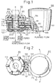
- Figures 1 and 2 show a partially sectioned side elevational view and a plan view of a water purifier with a diverter according to the present invention.
- the diverter 101 included in the water purifier can be detachably attached to a faucet 200 of a water supply pipe to select the water flow and a replaceable filter cartridge 102 which is detachably connected to the diverter 101 to filter the water supplied from the faucet 200 through the switching valve 101 to produce a purified water flow.
- the diverter 101 is comprised of a cylindrical shaft body (cylindrical portion) 111, a rotatable selecting member 112 which is rotatably attached to the outer peripheral surface of the shaft body 111, and a rotating ring 113 which is rotatably and coaxially mounted to the upper end of the shaft body 111.
- the diverter 101 can be detachably attached to the faucet 200 by the rotating ring 113 through a sealing packing 175 in a water tight fashion.
- the shaft body 111 is provided with a bottomed cylinder 114 and an annular flange 115 provided on the upper end of the cylinder 114 integral therewith.
- the cylinder 114 defines therein a water passage 116 having an upper open end to be connected to the faucet 200 to which the diverter 101 is attached.
- the cylinder 114 is provided on the peripheral wall thereof with a circular cross through hole (opening) 117 opening into the water passage 116.
- the rotatable selecting member 112 is rotated to select a "straight unfiltered water flow", a "spray unfiltered water flow", or a "purified water flow”. For the purified water flow, the water is introduced into the filter cartridge 102, as will be discussed hereinafter.
- the selecting member 112 is comprised of a plurality of radially extending lateral circular holes (branch passages) 118a, 118b and 118c (Fig. 9) at the same height level in the axial direction (vertical direction), so that the lateral holes 118a, 118b and 118c can be selectively connected to the through hole 117 of the cylinder 114 in accordance with the rotation of the selecting member 112.
- the branch passage 118a extends through the side wall of the selecting member 112 in the radial direction to form a first branch passage for the cartridge 102.
- the first branch passage 118a is provided on the outer end thereof with an outlet opening (cartridge opening) 119.
- the outlet opening 119 is sealed by an annular packing 120 having an opening 120a corresponding to the first branch passage 118a.
- the second and third branch passages 118b and 118c extend in the radial directions of the side wall of the selecting member 122 and are bent downward at the intermediate portions thereof to be connected to an outlet passage 121 for a straight unfiltered water flow (referred to as a straight outlet passage) and an outlet passage 122 for a spray unfiltered water flow (referred to as a spray or shower outlet passage).
- the straight outlet passage 121 which is, for example, in the form of a circular opening and the spray outlet passage 122 which is, for example, in the form of an annular opening are formed at the lower end of the selecting member 112.
- the straight outlet passage 121 and the spray outlet passage 122 are independent from one another by an annular wall 112b provided on the lower end of the selecting member 112.
- the spray outlet passage 122 is closed by an annular spray or shower attachment 123 detachably attached to the bottom of the selecting member 112 through a sealing packing (not shown).
- the shower attachment 123 has a lot of pores to produce a shower type flow (spray flow) of water passing therethrough.
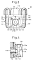
- the selecting member 112 is provided on the peripheral surface thereof with a pair of opposed projections 130 and 131 located on opposite sides of the cartridge opening 119, as shown in Fig. 2 or 3.
- the projections 130 and 131 are each provided with a generally U-shaped guide groove 134 (or 135) extending in a direction parallel with the axis X of the selecting member 112.
- the projections 130 and 131 are made integral with the selecting member 112 in a symmetrical arrangement with respect to the central axis of the cartridge opening 119 to form a generally angular C-shape projection as viewed in a plan view shown in Fig. 2.
- the identical guide grooves 134 and 135 formed on the opposed surfaces 130a and 131a of the projections 130 and 131 are provided with smoothly curved bottom surfaces whose height gradually increases from the upper end toward the lower end in Fig. 3.
- the bottoms of the projections 130 and 131 are also provided with stepped bottom surfaces 132 and 133 which constitute locking or engaging portions. Namely, the distance between the bottom surfaces of the opposed guide grooves 130 and 131 gradually decreases from the upper ends to the lower ends of the projections 130 and 131, except for the stepped locking bottom surfaces (flat surfaces) 132 and 133.
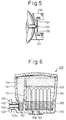
- the replaceable filter cartridge 102 is comprised of a hollow casing 141, and a bottom casing 170 integrally formed with the hollow casing 141, as shown in Fig. 6.
- the bottom casing 170 is provided with a generally T-shaped projection 172 as viewed in a plan view shown in Fig. 2.
- the projection 172 is comprised of a shaft portion 142 and a generally rectangular shaped plate portion 140 provided at the front end of the shaft portion 142.
- the shaft portion 142 is provided therein with a water passage 142a (Fig. 6) which can be connected to the cartridge opening 118a of the diverter 101 through the annular sealing packing 120.
- the plate portion 140 defines at the opposite sides thereof engaging portions (projections from the shaft portion 143 and 144) corresponding to the guide grooves 134 and 135 of the selecting member 112, so that the engaging portions 143 and 144 can be engaged in the corresponding guide grooves 134 and 135 when the filter cartridge 102 is attached to the diverter 101.
- the engaging portions 143 and 144 are respectively provided with elastically deformable arms 145 and 146 which extend downward therefrom.
- the elastically deformable arms 145 and 146 are provided on the front ends (free ends) thereof with enlarged heads 145a and 146a (projections) that project outward away from the water passage 142a from the front ends of the elastically deformable arms 145 and 146.
- the enlarged heads 145a and 146a are preferably spherical or semi-spherical.
- the hollow casing 141 of the diverter 102 receives therein an upright separation plate 151 in the vicinity of the water passage 142a.
- a first perforated separation filter 152 provided on the side of the separation plate 151 adjacent to the water passage 142a and somewhat above the latter.
- a second perforated separation filter 153 is provided on the other side of the separation plate 151 and at the upper portion of the hollow casing 141.
- An adsorbent (water purifying or filtering layer) 154 made of, for example, activated carbon (particles, powder or fiber), an ion-exchange resin, or calcium sulphite, etc., or a mixture of these components is provided on the first and second perforated filters 152 153 to absorb or adsorb and remove odors or organic impurities in the water to be supplied.
- a filter (water purifying or filtering layer) 156 made of, for example, a hollow fiber membrane is provided in a space of the upper casing 141 on the right side of the first perforated separation filter 151 and below the second perforated separation filter 153 to remove rust or bacteria, etc.
- the filter 156 is held by a holder 155 which is in turn held by the upper casing 141.
- the bottom casing 170 defines therein a purified water gathering chamber 157 below the filter 156.
- the bottom casing 170 is provided with a bottom opening (discharge port) 158 which is connected to the purified water gathering chamber 157 and opens into the atmosphere, so that the water purified through the filter cartridge 102 can be discharged from the discharge port 158.
- the engaging portions 143 and 144 of the cartridge 102 are inserted from above in the corresponding guide grooves 134 and 135 of the selecting member 112 of the diverter 101, so that the heads 145a and 146a of the elastically deformable arms 145 and 146 are engaged by the engaging surfaces 132 and 133 of the guide grooves 134 and 135.
- the elastically deformable arms 145 and 146 are elastically deformed in a direction to come close to each other.
- the filter cartridge 102 can be extremely easily and certainly detachably connected to the diverter 101 within an extremely short space of time.
- the width between the upper ends of the engaging portions 143 and 144 i.e., the width of the upper edge of the plate portion 140
- the width between the upper ends of the engaging portions 143 and 144 is large enough to prevent the plate portion 140 from passing over and through the lower ends (in Fig. 3) of the curved bottom surfaces of the guide grooves 134 and 135. Consequently, no detachment of the filter cartridge 102 from the diverter 101 in the downward direction occurs.
- a strong upward force above a predetermined value is applied to the filter cartridge 102 from the bottom thereof, so that the enlarged heads 145a and 146a of the elastically deformable arms 145 and 146 displaced on the engaging surfaces 132 and 133 of the guide grooves 134 and 135 are forced to ride over the lower ends of the curved bottom surfaces owing to the semi-spherical shape of the enlarged heads, while elastically deforming the elastically deformable arms 145 and 146 to come close to each other.
- the engaging portions 143 and 144 can be easily disengaged from the guide grooves 143 and 144 by the upward displacement of the filter cartridge 102, since the distance between the curved bottom surfaces of the guide grooves gradually increases during the disengagement movement.
- the user rotates the filter cartridge 102 (or the selecting member 112) in the clockwise or counterclockwise direction (indicated by arrows in Fig. 2) by a predetermined angle to selectively register the second or third branch passage 118b or 118c with the cross hole 117 of the cylinder 114.
- the second branch passage 118c is connected to the cross hole 117
- the third branch passage 118b is connected to the cross hole 117, respectively.
- three markings 179 which indicate angular positions of the selecting member 112 or the filter cartridge 102 corresponding to the "straight unfiltered water flow", the "spray unfiltered water flow” and the “purified water flow” are provided on the side surface of the selecting member 112 (or the filter cartridge 102).
- a reference marking 178 is provided for example on the flange 115 of the shaft body 111, so that when any one of the markings 179 is registered with the reference marking 178, the "straight unfiltered water flow", the "spray unfiltered water flow” or the “purified water flow” is established.
- the filter cartridge 102 When a user wants to use or drink purified water dispensed through the filter cartridge 102, the latter is attached to the diverter 101 attached to the water faucet 200 (Fig. 1) by the rotating ring 113 through the fastening ring 177 and the sealing packing 175, as mentioned above.
- the selecting member 112 is rotated directly or through the filter cartridge 102 to come to the angular position for the "purified water flow", in which the branch passage 118a is connected to the cartridge opening 117. Consequently, the water supplied from the water supply pipe through the faucet 200 is introduced into the main passage 116 of the shaft body 111.
- the water discharged from the outlet port 119 is introduced into the water inlet passage 142a of the filter cartridge 102.
- the water then passes through the first perforated separation filter 152, the adsorbent 154, the second perforated separation filter 153, the filter 156, and is discharged from the discharge port 158 of the water gathering chamber 157. During passing through the adsorbent 154 and the filter 156, the water is purified.
- the filter cartridge 102 can be extremely easily and quickly attached to the diverter 101 only by inserting the engaging portions 143 and 144 on the filter cartridge side in the corresponding guide grooves 134 and 135 on the diverter side without need for an additional separate connecting member, such as a fastener, etc., between the diverter and the filter cartridge. Namely, only one simple fitting operation is necessary to attach or detach the filter cartridge 102 to or from the diverter 101, thus resulting in a reduction of the time necessary for the attachment or detachment operation. It should be appreciated that no connecting mechanism using male and female screws (threaded portions) is employed in the present invention to connect the filter cartridge to the diverter, which simplifies the connecting operation.
- the total height of the switching valve (and the purifier) can be reduced since the immovable shaft portion is coaxially fitted in the rotatable selecting member, so that a large working space can be provided between the bottom of the switching valve and the bottom surface of the sink.
- the number of the components of the switching valve in the present invention is smaller than the components of the switching valve shown in Fig. 10.
- the switching valve 101 is comprised of the shaft body 111, the rotatable selecting ring 112, and the rotary ring 113, in the illustrated embodiment, the structure of the diverter is not limited to the illustrated embodiment.
- the filter cartridge 102 can be applied to any diverter 101 having an exposed branch passage corresponding to the branch passage 118a.
- FIG. 8 shows another embodiment of the connecting mechanism between the filter cartridge 102 and the diverter 101.
- a clipper 161 having a generally U-shaped cross section.
- the clipper 161 is made of a pair of side plates 161a and 161b of a generally rounded T-shape and a connecting plate 161b which connects the opposed side plates 161a and 161b.
- the clipper 161 exhibits a flexibility or elastic deformability due to the shape thereof.
- the width (space) "w" between the opposed side plates 161a and 161b is slightly smaller than the height "h" of the projections 130, 131 (or the plate portion 140).
- the clipper 161 when the clipper 161 is fitted on the plate portion 140 and the projections 130 and 131, the plate portion 140 and the projections 130 and 131 are held by the clipper 161 due to the resilient force of the side plates 161a and 161b which have been elastically slightly expanded to fit the plate portion 140 and the projections 130 and 131 therebetween.
- FIG. 10 shows a still another embodiment of a clipper shown in Fig. 8.
- the clipper 161A shown in Fig. 10 is provided on the lower plate 161a (one of the opposed side plates 161a) thereof, with an opening, hole, or recess 193.
- the other structure of the clipper 161A is substantially the same as the clipper 161.
- a small projection 191 (Fig. 11) is provided on the lower edge of the plate portion 140 of the cartridge 102.
- the plate portion provided with the projection 191 is indicated by 140A in Fig. 11.
- the elastically deformable arms 145 and 146 shown in Fig. 7 can be dispensed with in the modified embodiment shown in Fig. 11. It is possible to provide elastically deformable arms 145 and 146 with enlarged heads 145a and 146a, as shown in Fig. 7, on the plate portion 140A shown in Fig. 11, but the elastically deformable arms 145 and 146 can be dispensed with in the modified embodiment shown in Fig. 11. If the plate portion 140 has no elastically deformable arms 145 and 146 (Fig. 7), the shape of the guide grooves 134 and 135 (Fig. 5, etc.) of the switching valve 101 are correspondingly modified so as to snugly fit the plate portion 140A in the guide grooves 134 and 135.
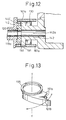
- the clipper 161A When the clipper 161A is attached to the connectiong portion (engaging portion) between the cartridge 102 and the switching valve 101, as discussed above with reference to Fig. 8, the projection 191 of the plate portion 140A is fitted in the opening or hole 193 of the clipper 161A, so that the clipper 161A can be firmly attached to the connecting portion (engaging portion) between the cartridge 102 and the switching valve 101 to cover or protect the same, as shown in Fig. 12.
- the clipper 161A can be detached from the connecting portion (engaging portion) between the cartridge 102 and the switching valve 101 when a predetermined external force strong enough to disengage the projection 191 from the opening 193 is applied thereto.
- Figure 13 shows still another embodiment of a clipper.
- the clipper 161B shown in Fig. 13 is additionally provided with a ring 195 integral therewith, in comparison with the clipper 161 shown in Fig. 8 or the clipper 161A shown in Fig. 10.
- the ring 195 whose axis Y-Y is coaxial to the axis X-X (Fig.
- the clipper 161B is rotatable between a closed position in which the connecting portion (engaging portion) between the cartridge 102 and the switching valve 101 is closed and covered by the clipper 161B, and an open position in which the connecting portion between the cartridge 102 and the switching valve 101 is opened or exposed, so that the cartridge can be detached from the switching valve, as mentioned above.
Landscapes
- Engineering & Computer Science (AREA)
- Water Supply & Treatment (AREA)
- Health & Medical Sciences (AREA)
- Life Sciences & Earth Sciences (AREA)
- Hydrology & Water Resources (AREA)
- Public Health (AREA)
- Chemical & Material Sciences (AREA)
- Chemical Kinetics & Catalysis (AREA)
- General Engineering & Computer Science (AREA)
- Mechanical Engineering (AREA)
- Water Treatment By Sorption (AREA)
Claims (21)
- Dispositif de dérivation (101) qui peut être solidarisé de manière libérable à un robinet (200) d'un tuyau d'alimentation en eau pour sélectionner une pluralité de passages de l'eau, comprenant :caractérisé en ce queun corps (111) qui définit dans sa partie interne un passage principal (116) pour l'eau pour être relié au robinet,un organe sélecteur tournant (112) qui peut être monté de manière rotative sur le corps et qui est muni d'une pluralité de passages (118a, 118b, 118c) de dérivation de l'eau qui peuvent être mis sélectivement en concordance avec le passage principal du corps en fonction de la rotation de l'organe sélecteur,le corps (111) est approximativement cylindrique,l'organe sélecteur tournant (112) peut être monté coaxialement sur le corps approximativement cylindrique, etau moins l'un des passages de dérivation (118a) de l'eau traverse la paroi latérale de l'organe sélecteur tournant et présente une extrémité de sortie ouverte exposée (119) à laquelle une cartouche filtrante peut être reliée.
- Dispositif de dérivation selon la revendication 1, dans lequel ledit organe sélecteur tournant (112) comporte deux passages (118b, 118c) de dérivation de l'eau pour un écoulement d'eau non filtré droit et un écoulement d'eau à épurer.
- Dispositif de dérivation selon la revendication 1, dans lequel ledit organe sélecteur tournant (112) comporte trois passages (118b, 118c, 118a) de dérivation de l'eau pour un écoulement d'eau non filtré droit, un écoulement non filtré pulvérisé, et un écoulement d'eau non filtré à épurer.
- Dispositif de dérivation selon la revendication 3, dans lequelles passages de dérivation latéraux de l'organe sélecteur tournant (112) s'étendent dans la direction radiale, etdeux des passages de dérivation (118b, 118c) sont pliés vers le bas au niveau de parties intermédiaires de l'organe sélecteur tournant pour être reliés à des passages de sortie pour un écoulement non filtré droit (121) et un écoulement non filtré pulvérisé (122), respectivement.
- Dispositif de dérivation selon la revendication 1, dans lequel ledit corps approximativement cylindrique (111) est muni sur sa paroi latérale périphérique d'au moins un trou transversal (117) qui est relié au passage principal (116) pour l'eau et qui débouche dans la surface périphérique extérieure (114) du corps approximativement cylindrique.
- Dispositif de dérivation selon la revendication 1, comprenant de plus une bague tournante (113) qui est prévue sur le corps approximativement cylindrique pour solidariser de manière libérable le dispositif de dérivation au robinet.
- Dispositif de dérivation selon la revendication 2, dans lequel ledit organe sélecteur comporte une ouverture de sortie (121) reliée au passage de dérivation de l'eau pour un écoulement d'eau non filtré droit.
- Dispositif de dérivation selon la revendication 3, dans lequel ledit organe sélecteur comporte des ouvertures de sortie (121, 122) reliées aux passages de dérivation de l'eau pour un écoulement d'eau non filtré droit et un écoulement d'eau non filtré pulvérisé.
- Dispositif de dérivation selon la revendication 8, comprenant de plus un accessoire de pulvérisation (123) solidarisé au fond de l'organe sélecteur (112) de façon à recouvrir l'ouverture de sortie pour un écoulement d'eau non filtré pulvérisé.
- Dispositif de dérivation selon la revendication 1, dans lequel ledit organe sélecteur (112) comporte une partie de connexion à laquelle une cartouche filtrante remplaçable peut être solidarisée de manière libérable.
- Dispositif de dérivation selon la revendication 10, dans lequel ladite partie de connexion comprend une saillie (130, 131) comportant une paire de rainures de guidage (134, 135).
- Dispositif de dérivation selon la revendication 11, dans lequel lesdites rainures de guidage comportent chacune une surface de fond courbe dont la hauteur augmente graduellement dans une direction prédéterminée.
- Dispositif de dérivation selon la revendication 12, dans lequel lesdites rainures de guidage (134, 135) comportent chacune une partie de surface de fond de verrouillage (132, 133) épaulée par rapport à la surface de fond courbe.
- Dispositif de dérivation selon la revendication 13, dans lequel lesdites rainures de guidage sont disposées selon une configuration symétrique par rapport à un axe de l'extrémité de sortie ouverte du au moins un passage de dérivation de l'eau.
- Dispositif de dérivation selon la revendication 11 muni d'une cartouche filtrante qui peut être solidarisée de manière libérable audit dispositif de dérivation, dans lequelladite cartouche filtrante épure l'eau à fournir par l'intermédiaire de l'organe sélecteur et comprend une partie de mise en contact (172) qui peut être insérée et emboítée dans les rainures de guidage.
- Dispositif de dérivation muni d'une cartouche filtrante selon la revendication 15, dans lequel ladite partie de mise en contact de la cartouche filtrante est munie d'une paire de bras déformables élastiquement (145, 146) qui sont déformés élastiquement par les surfaces de fond courbes des rainures de guidage (134, 135) pendant l'insertion de la partie de mise en contact dans les rainures de guidage.
- Dispositif de dérivation muni d'une cartouche filtrante selon la revendication 16, dans lequel lesdits bras déformables élastiquement de la partie de mise en contact de la cartouche filtrante sont munis chacun d'une tête agrandie (145a, 146a) qui peut être amenée à coopérer avec les parties de surface de fond de verrouillage des rainures de guidage lorsque les bras déformables élastiquement de la partie de mise en contact de la cartouche filtrante sont complètement insérés dans les rainures de guidage correspondantes.
- Dispositif de dérivation muni d'une cartouche filtrante selon la revendication 15, comprenant de plus un dispositif de serrage (161) qui peut être solidarisé à une partie de connexion (143, 144) entre le dispositif de dérivation et la cartouche filtrante pour retenir la partie de connexion.
- Dispositif de dérivation muni d'une cartouche filtrante selon la revendication 18, dans lequel ledit dispositif de serrage est muni d'une paire de plaques latérales (161a) et une plaque de liaison (161b) qui relie les plaques latérales entre elles pour obtenir approximativement une forme de U dans une coupe transversale, de sorte que les plaques latérales peuvent être déformées élastiquement.
- Dispositif de dérivation muni d'une cartouche filtrante selon la revendication 19, dans lequel ledit dispositif de serrage comporte sur l'une des plaques latérales une ouverture ou évidement (193), et dans lequel ladite partie de mise en contact (140) de la cartouche filtrante présente une saillie (191) qui peut être engagée dans l'ouverture ou évidement du dispositif de serrage lorsque le dispositif de serrage est solidarisé à la partie de connexion entre le dispositif de dérivation et la cartouche filtrante.
- Dispositif de dérivation muni d'une cartouche filtrante selon la revendication 19, dans lequel ledit dispositif de serrage est muni d'un organe annulaire (195) venu de matière avec celui-ci, qui peut être solidarisé de manière rotative et coaxiale au dispositif de dérivation.
Priority Applications (1)
| Application Number | Priority Date | Filing Date | Title |
|---|---|---|---|
| EP97110392A EP0798424B1 (fr) | 1994-04-06 | 1995-04-06 | Déflecteur d'écoulement et purificateur muni d'un tel déflecteur |
Applications Claiming Priority (6)
| Application Number | Priority Date | Filing Date | Title |
|---|---|---|---|
| JP68823/94 | 1994-04-06 | ||
| JP06882394A JP3471412B2 (ja) | 1994-04-06 | 1994-04-06 | 切換弁及び浄水器 |
| JP6882394 | 1994-04-06 | ||
| JP6271496A JP2839848B2 (ja) | 1994-11-04 | 1994-11-04 | 浄水器 |
| JP271496/94 | 1994-11-04 | ||
| JP27149694 | 1994-11-04 |
Related Child Applications (1)
| Application Number | Title | Priority Date | Filing Date |
|---|---|---|---|
| EP97110392A Division EP0798424B1 (fr) | 1994-04-06 | 1995-04-06 | Déflecteur d'écoulement et purificateur muni d'un tel déflecteur |
Publications (3)
| Publication Number | Publication Date |
|---|---|
| EP0677619A2 EP0677619A2 (fr) | 1995-10-18 |
| EP0677619A3 EP0677619A3 (fr) | 1996-02-21 |
| EP0677619B1 true EP0677619B1 (fr) | 1999-10-20 |
Family
ID=26410014
Family Applications (2)
| Application Number | Title | Priority Date | Filing Date |
|---|---|---|---|
| EP95105196A Expired - Lifetime EP0677619B1 (fr) | 1994-04-06 | 1995-04-06 | Déflecteur d'écoulement et purificateur muni d'un tel déflecteur |
| EP97110392A Expired - Lifetime EP0798424B1 (fr) | 1994-04-06 | 1995-04-06 | Déflecteur d'écoulement et purificateur muni d'un tel déflecteur |
Family Applications After (1)
| Application Number | Title | Priority Date | Filing Date |
|---|---|---|---|
| EP97110392A Expired - Lifetime EP0798424B1 (fr) | 1994-04-06 | 1995-04-06 | Déflecteur d'écoulement et purificateur muni d'un tel déflecteur |
Country Status (5)
| Country | Link |
|---|---|
| US (1) | US5653868A (fr) |
| EP (2) | EP0677619B1 (fr) |
| KR (1) | KR0156082B1 (fr) |
| DE (2) | DE69531837D1 (fr) |
| TW (1) | TW298104U (fr) |
Cited By (1)
| Publication number | Priority date | Publication date | Assignee | Title |
|---|---|---|---|---|
| CN107202189A (zh) * | 2016-03-16 | 2017-09-26 | 珠海格力电器股份有限公司 | 废水比阀及反渗透滤芯净水机 |
Families Citing this family (31)
| Publication number | Priority date | Publication date | Assignee | Title |
|---|---|---|---|---|
| GB9707949D0 (en) * | 1997-04-19 | 1997-06-11 | Walker David M | Water treatment and delivery apparatus |
| US5935426A (en) | 1997-08-08 | 1999-08-10 | Teledyne Industries, Inc., A California Corporation | Water treatment device with volumetric and time monitoring features |
| USD398703S (en) | 1997-09-09 | 1998-09-22 | The Clorox Company | Faucet mounted water treatment apparatus |
| USD398369S (en) | 1997-09-09 | 1998-09-15 | The Clorox Company | Faucet mounted water treatment device |
| US6096197A (en) | 1997-12-11 | 2000-08-01 | Hughes; Douglass E. | Shower filter for chlorine removal and scale deposit prevention |
| AU2234399A (en) * | 1998-01-21 | 1999-08-09 | Clorox Company, The | Faucet mounted water filter |
| US5976362A (en) * | 1998-04-01 | 1999-11-02 | The Clorox Company | Faucet mounted water filter |
| JP2000051869A (ja) * | 1998-08-07 | 2000-02-22 | Karufa Chemical Kk | 生活用水の浄水装置 |
| RU2150987C1 (ru) * | 1998-09-17 | 2000-06-20 | Общество с ограниченной ответственностью "Аквафор" | Способ фильтрационной очистки жидкости, кран и устройство для фильтрационной очистки жидкости |
| US6251274B1 (en) * | 1999-03-16 | 2001-06-26 | Envirogard Products Limited | Faucet attachment for treating water |
| US6881333B2 (en) | 2001-03-26 | 2005-04-19 | Osaka Gas Chemicals Co., Ltd. | Water purifier filtration portion, water purifier main body, and water purifier including the both |
| NL1020607C2 (nl) * | 2002-05-15 | 2003-11-18 | Prime Water Systems Gmbh | Vloeistofdoorstroominrichting. |
| US7077153B2 (en) * | 2002-07-17 | 2006-07-18 | Newfrey Llc | Side control faucet with diverter assembly |
| US7252757B2 (en) * | 2002-09-09 | 2007-08-07 | Clarity Filters Llc | Faucet-mounted water filtration device including gate position sensor |
| US7258781B2 (en) * | 2002-09-09 | 2007-08-21 | Clarity Filters Llc | Single-use long-life faucet-mounted water filtration devices |
| USD533622S1 (en) * | 2003-10-01 | 2006-12-12 | Water Pik, Inc. | End-of-faucet filter |
| US7326334B2 (en) | 2003-10-01 | 2008-02-05 | Instapure Brands, Inc. | End-of-faucet filter |
| KR101272966B1 (ko) | 2003-10-17 | 2013-06-10 | 액세스 비지니스 그룹 인터내셔날 엘엘씨 | 변환기 밸브 조립체 및 유체 유동을 변환하는 방법 |
| USD541372S1 (en) | 2005-11-01 | 2007-04-24 | Clarity Filters Llc | Water filter |
| US7721761B2 (en) * | 2007-01-31 | 2010-05-25 | Masco Corporation Of Indiana | Diverter integrated into a side sprayer |
| WO2009143352A1 (fr) | 2008-05-21 | 2009-11-26 | Masco Corporation Of Indiana | Asperseur et inverseur intégrés à côté d’un robinet de cuisine |
| US8272318B2 (en) * | 2008-12-18 | 2012-09-25 | Whirlpool Corporation | Liquid flow control and beverage preparation apparatuses, methods and systems |
| US8268168B2 (en) * | 2009-12-18 | 2012-09-18 | Hoi Kwan Henry Mang | Filter unit for shower system |
| US9486817B2 (en) * | 2013-03-15 | 2016-11-08 | Delta Faucet Company | Ozone shower device |
| CN204201179U (zh) * | 2014-09-30 | 2015-03-11 | 厦门建霖工业有限公司 | 一种两路出水装置 |
| CN108368696B (zh) | 2015-10-08 | 2021-05-11 | As 美国股份有限公司 | 集成的龙头过滤系统 |
| US10004351B2 (en) * | 2016-01-22 | 2018-06-26 | Allan Erhart | Hot water dispenser adapter device |
| DE102016107485A1 (de) * | 2016-04-22 | 2017-10-26 | Poromembrane Gmbh | Wasseraufbereitungsvorrichtung |
| DE102018114582A1 (de) | 2018-06-18 | 2019-12-19 | Franke Technology And Trademark Ltd. | Filtereinsatz für eine Wasserauslaufarmatur mit Trinkwasserfilter |
| DE102018114581A1 (de) | 2018-06-18 | 2019-12-19 | Franke Technology And Trademark Ltd. | Wasserauslaufarmatur mit Trinkwasserfilter |
| CN115726433B (zh) * | 2022-12-13 | 2023-06-20 | 江苏城乡建设职业学院 | 一种智能楼宇供水设备 |
Citations (1)
| Publication number | Priority date | Publication date | Assignee | Title |
|---|---|---|---|---|
| JPH063233U (ja) * | 1992-06-26 | 1994-01-18 | リンナイ株式会社 | 焼物調理器の支持台昇降装置 |
Family Cites Families (16)
| Publication number | Priority date | Publication date | Assignee | Title |
|---|---|---|---|---|
| FR617340A (fr) * | 1926-06-09 | 1927-02-17 | Coulau Et Mallot | Brise-jet démontable |
| US2327306A (en) * | 1941-02-15 | 1943-08-17 | Orloff W Holden | Faucet strainer |
| GB855603A (en) * | 1957-03-13 | 1960-12-07 | Prec Electronic Terminations L | Fastener for coupling tubular elements |
| FR1240700A (fr) * | 1959-07-31 | 1960-09-09 | Vallourec | Raccord pour canalisations de fluide |
| CH420750A (de) * | 1962-03-13 | 1966-09-15 | Shell Int Research | Lösbare Rohrkupplung |
| US3789991A (en) * | 1971-08-23 | 1974-02-05 | Z Krongos | Water filter device |
| AU483820B2 (en) * | 1974-06-25 | 1976-01-08 | Aqua-Chem, Inc | Filter |
| US4172796A (en) * | 1975-09-29 | 1979-10-30 | Teledyne Industries, Inc. | Water purifier apparatus |
| JPS57181394A (en) * | 1981-05-01 | 1982-11-08 | Kawasaki Steel Corp | Preventing method for contamination of steel plate zinc electroplated on one side |
| DE8434109U1 (de) * | 1984-11-22 | 1986-03-27 | Knebel & Röttger GmbH & Co, 5860 Iserlohn | Auslauf-Rohrleitungsschalter mit einem Zulauf und zwei Abläufen |
| US4686037A (en) * | 1985-03-27 | 1987-08-11 | Teledyne Industries, Inc. | Water filter apparatus |
| DE8632798U1 (de) * | 1986-12-06 | 1987-02-05 | Hane, Heinz, 8900 Augsburg | Allseitiges schwenkbares, strahlverstellbares Auslaufmundstück für Wasserauslaufventile |
| CH676492A5 (fr) * | 1988-05-02 | 1991-01-31 | Nussbaum & Co Ag R | |
| JPH063233Y2 (ja) * | 1989-03-17 | 1994-01-26 | ジョプラックス株式会社 | 流水切換具 |
| JPH0557276A (ja) * | 1991-03-16 | 1993-03-09 | Nippondenso Co Ltd | 浄水装置 |
| US5279329A (en) * | 1992-11-16 | 1994-01-18 | Amway Corporation | Faucet diverter valve |
-
1995
- 1995-04-05 US US08/416,981 patent/US5653868A/en not_active Expired - Lifetime
- 1995-04-06 KR KR1019950008252A patent/KR0156082B1/ko not_active Expired - Fee Related
- 1995-04-06 EP EP95105196A patent/EP0677619B1/fr not_active Expired - Lifetime
- 1995-04-06 DE DE69531837T patent/DE69531837D1/de not_active Expired - Lifetime
- 1995-04-06 TW TW084215690U patent/TW298104U/zh unknown
- 1995-04-06 EP EP97110392A patent/EP0798424B1/fr not_active Expired - Lifetime
- 1995-04-06 DE DE69512819T patent/DE69512819T2/de not_active Expired - Lifetime
Patent Citations (1)
| Publication number | Priority date | Publication date | Assignee | Title |
|---|---|---|---|---|
| JPH063233U (ja) * | 1992-06-26 | 1994-01-18 | リンナイ株式会社 | 焼物調理器の支持台昇降装置 |
Cited By (2)
| Publication number | Priority date | Publication date | Assignee | Title |
|---|---|---|---|---|
| CN107202189A (zh) * | 2016-03-16 | 2017-09-26 | 珠海格力电器股份有限公司 | 废水比阀及反渗透滤芯净水机 |
| CN107202189B (zh) * | 2016-03-16 | 2019-08-23 | 珠海格力电器股份有限公司 | 废水比阀及反渗透滤芯净水机 |
Also Published As
| Publication number | Publication date |
|---|---|
| EP0798424B1 (fr) | 2003-09-24 |
| EP0798424A3 (fr) | 1998-05-20 |
| KR0156082B1 (ko) | 1999-02-18 |
| HK1010407A1 (en) | 1999-06-17 |
| US5653868A (en) | 1997-08-05 |
| KR950028805A (ko) | 1995-11-22 |
| EP0677619A3 (fr) | 1996-02-21 |
| DE69512819T2 (de) | 2000-03-16 |
| EP0798424A2 (fr) | 1997-10-01 |
| TW298104U (en) | 1997-02-11 |
| DE69531837D1 (de) | 2003-10-30 |
| HK1003513A1 (en) | 1998-10-30 |
| DE69512819D1 (de) | 1999-11-25 |
| EP0677619A2 (fr) | 1995-10-18 |
Similar Documents
| Publication | Publication Date | Title |
|---|---|---|
| EP0677619B1 (fr) | Déflecteur d'écoulement et purificateur muni d'un tel déflecteur | |
| US4980073A (en) | Valve stem for a filter device | |
| US4770768A (en) | Water filter apparatus and aerator assembly | |
| US4857189A (en) | Filter cartridge with a lugged concentric closure portion | |
| US4686037A (en) | Water filter apparatus | |
| CA2573465C (fr) | Adaptateur de filtre | |
| US6258266B1 (en) | Faucet mount water filtration device | |
| US7407148B2 (en) | Rotary valve assembly for fluid filtration system | |
| US5336406A (en) | Replaceable filter cartridge and head assembly with safety shut-off valve | |
| CA2509813C (fr) | Dispositifs de filtration d'eau monte sur un robinet durables et a usage unique | |
| US20060108267A1 (en) | Single-use long-life faucet-mounted water filtration devices | |
| HK1010407B (en) | Diverter and water purifier having same | |
| US4968440A (en) | Coupling element for a filter device | |
| HK1003513B (en) | Diverter and water purifier having same | |
| JP3702530B2 (ja) | 浄水器 | |
| JPH09264441A (ja) | 切換弁および浄水器 | |
| JP3049769U (ja) | ろ水器用水流切換弁 | |
| EP0349727A2 (fr) | Dispositif filtrant | |
| US5078176A (en) | Valve assembly for a filter device | |
| JP2839848B2 (ja) | 浄水器 | |
| JPH0248005Y2 (fr) | ||
| JP2002356891A (ja) | 緊急遮断弁付きの水栓及び水栓用のカートリッジ | |
| JP2003136055A (ja) | 浄水カートリッジ装着装置 | |
| JP3246269B2 (ja) | 水スイッチ | |
| CN216430583U (zh) | 一种水路切换器 |
Legal Events
| Date | Code | Title | Description |
|---|---|---|---|
| PUAI | Public reference made under article 153(3) epc to a published international application that has entered the european phase |
Free format text: ORIGINAL CODE: 0009012 |
|
| 17P | Request for examination filed |
Effective date: 19950406 |
|
| AK | Designated contracting states |
Kind code of ref document: A2 Designated state(s): DE FR GB IT |
|
| PUAL | Search report despatched |
Free format text: ORIGINAL CODE: 0009013 |
|
| AK | Designated contracting states |
Kind code of ref document: A3 Designated state(s): DE FR GB IT |
|
| 17Q | First examination report despatched |
Effective date: 19961213 |
|
| GRAG | Despatch of communication of intention to grant |
Free format text: ORIGINAL CODE: EPIDOS AGRA |
|
| GRAG | Despatch of communication of intention to grant |
Free format text: ORIGINAL CODE: EPIDOS AGRA |
|
| GRAH | Despatch of communication of intention to grant a patent |
Free format text: ORIGINAL CODE: EPIDOS IGRA |
|
| GRAH | Despatch of communication of intention to grant a patent |
Free format text: ORIGINAL CODE: EPIDOS IGRA |
|
| GRAA | (expected) grant |
Free format text: ORIGINAL CODE: 0009210 |
|
| AK | Designated contracting states |
Kind code of ref document: B1 Designated state(s): DE FR GB IT |
|
| XX | Miscellaneous (additional remarks) |
Free format text: TEILANMELDUNG 97110392.4 EINGEREICHT AM 25/06/97. |
|
| REF | Corresponds to: |
Ref document number: 69512819 Country of ref document: DE Date of ref document: 19991125 |
|
| ET | Fr: translation filed | ||
| ITF | It: translation for a ep patent filed | ||
| PLBE | No opposition filed within time limit |
Free format text: ORIGINAL CODE: 0009261 |
|
| STAA | Information on the status of an ep patent application or granted ep patent |
Free format text: STATUS: NO OPPOSITION FILED WITHIN TIME LIMIT |
|
| 26N | No opposition filed | ||
| REG | Reference to a national code |
Ref country code: GB Ref legal event code: IF02 |
|
| PGFP | Annual fee paid to national office [announced via postgrant information from national office to epo] |
Ref country code: FR Payment date: 20080312 Year of fee payment: 14 |
|
| PGFP | Annual fee paid to national office [announced via postgrant information from national office to epo] |
Ref country code: IT Payment date: 20080424 Year of fee payment: 14 |
|
| PGFP | Annual fee paid to national office [announced via postgrant information from national office to epo] |
Ref country code: GB Payment date: 20080409 Year of fee payment: 14 |
|
| GBPC | Gb: european patent ceased through non-payment of renewal fee |
Effective date: 20090406 |
|
| REG | Reference to a national code |
Ref country code: FR Ref legal event code: ST Effective date: 20091231 |
|
| PG25 | Lapsed in a contracting state [announced via postgrant information from national office to epo] |
Ref country code: GB Free format text: LAPSE BECAUSE OF NON-PAYMENT OF DUE FEES Effective date: 20090406 Ref country code: FR Free format text: LAPSE BECAUSE OF NON-PAYMENT OF DUE FEES Effective date: 20091222 |
|
| PG25 | Lapsed in a contracting state [announced via postgrant information from national office to epo] |
Ref country code: IT Free format text: LAPSE BECAUSE OF NON-PAYMENT OF DUE FEES Effective date: 20090406 |
|
| PGFP | Annual fee paid to national office [announced via postgrant information from national office to epo] |
Ref country code: DE Payment date: 20140430 Year of fee payment: 20 |
|
| REG | Reference to a national code |
Ref country code: DE Ref legal event code: R071 Ref document number: 69512819 Country of ref document: DE |