EP0678432B1 - Kuppelklemme für ein von einem kabelgezogenem Fahrzeug - Google Patents
Kuppelklemme für ein von einem kabelgezogenem Fahrzeug Download PDFInfo
- Publication number
- EP0678432B1 EP0678432B1 EP95410034A EP95410034A EP0678432B1 EP 0678432 B1 EP0678432 B1 EP 0678432B1 EP 95410034 A EP95410034 A EP 95410034A EP 95410034 A EP95410034 A EP 95410034A EP 0678432 B1 EP0678432 B1 EP 0678432B1
- Authority
- EP
- European Patent Office
- Prior art keywords
- cable
- lever
- clamp according
- jaws
- clamp
- Prior art date
- Legal status (The legal status is an assumption and is not a legal conclusion. Google has not performed a legal analysis and makes no representation as to the accuracy of the status listed.)
- Expired - Lifetime
Links
- 230000033001 locomotion Effects 0.000 claims description 9
- 230000005540 biological transmission Effects 0.000 claims description 5
- 230000008878 coupling Effects 0.000 claims description 4
- 238000010168 coupling process Methods 0.000 claims description 4
- 238000005859 coupling reaction Methods 0.000 claims description 4
- 230000006835 compression Effects 0.000 claims description 3
- 238000007906 compression Methods 0.000 claims description 3
- 230000003247 decreasing effect Effects 0.000 claims description 2
- 210000003127 knee Anatomy 0.000 description 10
- 230000007935 neutral effect Effects 0.000 description 6
- 230000002427 irreversible effect Effects 0.000 description 1
- 238000005096 rolling process Methods 0.000 description 1
Images



Classifications
-
- B—PERFORMING OPERATIONS; TRANSPORTING
- B61—RAILWAYS
- B61B—RAILWAY SYSTEMS; EQUIPMENT THEREFOR NOT OTHERWISE PROVIDED FOR
- B61B12/00—Component parts, details or accessories not provided for in groups B61B7/00 - B61B11/00
- B61B12/12—Cable grippers; Haulage clips
- B61B12/125—Cable grippers; Haulage clips for non aerial ropeways, e.g. on or under the ground
Definitions
- the invention relates to a disengageable coupling pliers of a vehicle to a towing cable of a track transport on own site, including a control of the clamp fixed to the bottom of the vehicle, a keel integral with the control mechanism and having a branch vertical, which extends vertically downward towards of the towing cable, being laterally offset from the vertical plane containing the cable and a horizontal branch which extends the vertical branch at right angles and extends across the track above the cable, a pair of jaw carried by the horizontal branch and of which at least one jaw mobile is slidably mounted to come selectively in one closed cable clamping position and in an open position of cable release and transmission device movement between the control mechanism and the movable jaw to control the opening and closing of the clamp, see for example WO 81/02275.
- Cable traction of vehicles in a own site transport has many advantages, particularly simplicity and reliability, but it requires the use of disengageable pliers, for coupling and uncoupling of the vehicle from the cable, the opening and closure are perfectly ensured, in order to avoid any risk of slip of the clamp on the cable and all false maneuver.
- Known clamps are complicated and often combined with multiple control systems to avoid any accident.
- the present invention aims to allow the realization a clamp of simple structure, the operation of which is perfectly reliable and this clamp is characterized in that said motion transmission device comprises a rod rigid, rotatably mounted inside the keel and bearing at its upper end a crank and that the crank is attacked by a spring-loaded toggle of the said mechanism control, likely to occupy an extension position and passing neutral, where the knee brace exerts a force maximum cable tightening and a broken trigger position spring and jaw opening.
- the rigid rod rotatably mounted inside the keel, ensures a reliable connection between the jaws projecting from the bottom of the vehicle and the control mechanism, which is arranged to the shelter directly under the bottom or is incorporated into the latter.
- the position of the jaws is faithfully represented by the position the crank wedged on the upper end of the rod and this crank is attacked by a spring-loaded toggle, which ensures stable opening and closing positions of the pliers.
- the knee switch is controlled by a cylinder, for example hydraulic and the assembly is arranged so that during a jaw closing command, the cylinder exerts during the jaw approach phase almost zero force, this force becoming maximum when tightening the cable and decreasing thereafter to become null or even negative, during the passing the neutral point of the knee lifter.
- the opening of the jaws is ensured as soon as the cylinder has brought the knee switch below the neutral.
- the knee brace comprises one or preferably two levers telescopic, each associated with a compression spring, advantageously constituted by a stack of washers elastic, which stress the telescopic lever in extension.
- One end of the toggle joint is articulated at a fixed point while the opposite end is hinged at the crank.
- the cylinder rod is articulated on the axis of the knee pad.
- the fixed jaw is shaped on the horizontal branch of the keel, which is arranged in a guideway of a slide forming the movable jaw.
- the slide carries a articulation pin of a keyed crank on the lower end of the rigid rod.
- a track 10 on its own site, consists of two running tracks 14.15, each associated with a running track guide 16.17.
- the vehicles 18 traveling on track 10 are provided with running wheels 19 and guide wheels 20, which cooperate with the rolling tracks 14,15 and the guide tracks 16.17.
- These 19,20 wheels are bandaged pneumatic, but it is clear that the invention is applicable to railway tracks and vehicles of any other type.
- a cable tractor 11, in the form of an endless loop with return strand 12, extends in the axis of the track, being guided by pulleys support and holding 13 and being driven by a motor (not shown).
- a clamp is attached to the bottom of the vehicle 18 21, capable of enclosing the cable 11 to couple the vehicle to this tow cable.
- Clamp 21 includes a keel 22, having a vertical branch 23 projecting downwards and laterally offset for crossing the pulleys 13 and a horizontal branch 24, which extends the branch at right angles vertical 23 and extends transversely above the cable 11.
- the horizontal branch 24 carries a pair of jaws 25.26, of which one 25 is fixed and the other 26 is movable to constitute disengageable pliers.
- the movable jaw 26 is connected by a movement transmission device to a mechanism control 27 fixed to the bottom of the vehicle 18. This mechanism 27 controls the opening and closing of the clamp 21 and so coupling and uncoupling of the vehicle 18 to the cable tractor 11.
- the horizontal branch 24 is shaped at its end in a fixed jaw 25, subdivided into two parts, which surround a slide 28, movable transversely to track 10.
- the slide 28 carries, opposite the fixed jaw 25, the movable jaw 26 to form a cable clamping jaw 11.
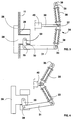
- a rigid rod vertical 29 In the vertical branch 23 is rotatably mounted a rigid rod vertical 29, at the ends of which are keyed respectively a lower crank 30 and a crank upper 31.
- the lower crank 30 is articulated on a pin 32 carried by slide 28, so as to transform a rotation of the rod 29 in a sliding of the slide 28.
- the upper crank 31 belongs to the control mechanism 27 and it is articulated to a lever 33 of a toggle joint 34, the other lever 35 of which is articulated at a fixed point 36.
- the two levers 33,35 are connected by the axis 37 of the toggle joint 34.
- Each lever 33, 35 is in two telescopic parts, between which a compression spring 38 is interposed, consisting, for example, of a stack of washers elastic, which urge the lever 33,35 in extension.
- AT the axis 37 of the toggle joint 34 is articulated at the end of a rod 39 of a jack 40, for example hydraulic or pneumatic, to control the extension or vice versa the breaking of the knee pad 34.
- the assembly is arranged so that in the position extension of the toggle joint 34, represented in FIG. 3, the jaws 25.26 grip the cable 11 with a clamping force corresponding to that of the springs 38, multiplied by the arms lever lever of the cranks 30.31.
- Neutral knee brace 34 is slightly exceeded and this extension position is thus a stable position for closing the clamp 21.
- the opening of the clamp 21 is controlled by the jack 40, which moves axis 37 of knee lifter 34 to the left on the Figure 3, thereby causing the toggle break 34 and the pivoting of the cranks 30.31 in the opposite direction Clockwise.
- the slide 28 is moved towards the left in the jaws open position 25,26, shown in the figure 4.
- FIG. 5 represents the force exerted by the jack 40 to operate the clamp from the open position O, shown in Figure 4, in position F of Figure 3.
- the toggle system 34 ensures thereafter, due to the gradual arrival in knee extension, a decrease in this force, which becomes zero in neutral and even negative after crossing of the latter. It is clear that as soon as the cylinder has crossed the maximum value of the force the movement of closure continues automatically and the risk of unfinished closure is almost zero.
- the structure of the clamp is simple, in particular the part in projection formed by the jaws 25.26.
Landscapes
- Engineering & Computer Science (AREA)
- Transportation (AREA)
- Mechanical Engineering (AREA)
- Automobile Manufacture Line, Endless Track Vehicle, Trailer (AREA)
- Flexible Shafts (AREA)
- Handcart (AREA)
- Vehicle Cleaning, Maintenance, Repair, Refitting, And Outriggers (AREA)
- Clamps And Clips (AREA)
- Installation Of Indoor Wiring (AREA)
- Gripping Jigs, Holding Jigs, And Positioning Jigs (AREA)
- Vehicle Body Suspensions (AREA)
- Agricultural Machines (AREA)
- Tents Or Canopies (AREA)
Claims (10)
- Abkuppelbarer Kupplungshaken eines Fahrzeugs (18) an einem Zugseil (11) einer Transportanlage (10) mit eigenem Gleis, mit einem Steuermechnismus (27) des am Boden des Fahrzeugs befestigten Hakens, einem mit dem Steuermechanismus (27) einen Teil bildenden Kiel (22) mit einem senkrechten Schenkel (23), der sich senkrecht nach unten in Richtung des Zugseils (11) erstreckt und seitlich in Bezug auf die senkrechte Ebene mit dem Seil und einem waagerechten Schenkel (24) verlagert ist, der den senkrechten Schenkel (23) winkelförmig verlängert und sich lotrecht zum Gleis (10) erstreckt, einem vom waagerechten Schenkel (24) getragenen Backenpaar (25, 26), von dem mindestens eine mobile Backe (26) gleitend montiert ist, um wahlweise eine geschlossene Spannposition des Seils (11) und eine geöffnete Freisetzungsposition des Seils einzunehmen, und einer Übertragungsvorrichtung der Bewegung (29-31) zwischen dem Steuermechanismus (27) und der mobilen Backe (26), um das Öffnen und Schliessen des Haken zu steuern, dadurch gekennzeichnet, dass die besagte Bewegungsübertragungsvorrichtung eine starre Stange (29) aufweist, die drehend um den Kiel (22) herum montiert ist und an ihrem oberen Ende eine Handkurbel (31) aufweist, und dass die Handkurbel (31) von einem Kniehebel (34) mit Feder (38) des besagten Steuermechanismus (27) angegriffen wird, der eine Extensions- und Überschreitungsposition des Totpunkts einnehmen kann, wobei der Kniehebel (34) eine maximale Spannkraft des Seils (11) ausübt, und eine unterbrochene Entspannungsposition der Feder (38) und Öffnungsposition der Backen (25, 26).
- Haken nach Anspruch 1, dadurch gekennzeichnet, dass einer der Hebel (33, 35) des Kniehebels (34) teleskopisch ist und eine Druckfeder (38) umfasst, die den Hebel in Extension beaufschlagt.
- Haken nach Anspruch 1 oder 2, dadurch gekennzeichnet, dass eines der Enden des Kniehebels (34) an der besagten Handkurbel (31) angelenkt ist, und dass das gegenüberliegende Ende an einem Festpunkt (36) angelenkt ist.
- Haken nach Anspruch 1, 2 oder 3, dadurch gekennzeichnet, dass er einen Steuerzylinder (40) umfasst, der mit dem Kniehebel (34) zusammenwirkt, um wahlweise die Extension und die Unterbrechung des Kniehebels zu bewirken.
- Haken nach Anspruch 4, dadurch gekennzeichnet, dass der Zylinder (40) auf die Gelenkachse (37) der beiden Hebel (33, 35) des Kniehebels (34) einwirkt.
- Haken nach Anspruch 4 oder 5, dadurch gekennzeichnet, dass die vom Zylinder (40) auf den Kniehebel (34) ausgeübte Kraft, um die Backen (25, 26) aus der geöffneten Position in die geschlossene Position zu versetzen, während der Annäherungsbewegung der Seilbacken (11) praktisch gleich null ist, um ihren maximalen Wert zu erreichen, wenn die Backen gegen das Seil drücken, und um danach abzunehmen und wieder auf Null zurückzufallen, oder umgekehrt, wenn der Totpunkt überschritten wird.
- Haken nach einem der vorherigen Ansprüche, dadurch gekennzeichnet, dass die beiden Hebel (33, 35) des Kniehebels (34) teleskopisch sind, und dass jeder Hebel einen Stapel von Federscheiben (38) umfasst, die den Hebel in Extension belasten.
- Haken nach einem der vorherigen Ansprüche, dadurch gekennzeichnet, dass das untere Ende der Drehstange (29) eine an der mobilen Backe (26) angelenkte untere Handkurbel (30) aufweist, um die Rotationsbewegung der Stange (29) in eine Gleitbewegung der Backe umzuwandeln.
- Haken nach einem der vorherigen Ansprüche, dadurch gekennzeichnet, dass der besagte waagerechte Schenkel (24) als feste Backe (25) ausgebildet und als Gleitschiene angeordnet ist, und dass die mobile Backe (26) als von der besagten Gleitschiene geführter Schieber (28) ausgebildet ist.
- Haken nach Anspruch 9, dadurch gekennzeichnet, dass er eine untere Handkurbel (30) aufweist, vor der ein Ende auf der starren Stange (29) aufgeklemmt ist, und deren gegenüberliegendes Ende an einem vom Schieber (28) getragenen Zapfen (32) angelenkt ist.
Applications Claiming Priority (2)
| Application Number | Priority Date | Filing Date | Title |
|---|---|---|---|
| FR9405120A FR2719012B1 (fr) | 1994-04-22 | 1994-04-22 | Pince débrayable d'un véhicule tracté par câble. |
| FR9405120 | 1994-04-22 |
Publications (2)
| Publication Number | Publication Date |
|---|---|
| EP0678432A1 EP0678432A1 (de) | 1995-10-25 |
| EP0678432B1 true EP0678432B1 (de) | 1998-03-04 |
Family
ID=9462591
Family Applications (1)
| Application Number | Title | Priority Date | Filing Date |
|---|---|---|---|
| EP95410034A Expired - Lifetime EP0678432B1 (de) | 1994-04-22 | 1995-04-13 | Kuppelklemme für ein von einem kabelgezogenem Fahrzeug |
Country Status (7)
| Country | Link |
|---|---|
| US (1) | US5520116A (de) |
| EP (1) | EP0678432B1 (de) |
| JP (1) | JP3665106B2 (de) |
| AT (1) | ATE163603T1 (de) |
| CA (1) | CA2146105C (de) |
| ES (1) | ES2116054T3 (de) |
| FR (1) | FR2719012B1 (de) |
Families Citing this family (6)
| Publication number | Priority date | Publication date | Assignee | Title |
|---|---|---|---|---|
| FR2758116B1 (fr) | 1997-01-06 | 1999-02-05 | Pomagalski Sa | Pince debrayable d'une installation de transport a cable tracteur |
| AU778081B2 (en) | 1999-03-25 | 2004-11-11 | Tepha, Inc. | Medical devices and applications of polyhydroxyalkanoate polymers |
| IT1308895B1 (it) * | 1999-05-11 | 2002-01-11 | Impero Automazioni S P A | Sistema flessibile modulare di gestione del carico lungo il percorsosu rotaia, in impianti a fune,per la movimentazione aerea di carrelli |
| EP2431475B1 (de) | 2002-05-10 | 2019-07-10 | Tepha, Inc. | Bioabsorbierbares polymer mit 2-hydroxysäure-monomeren |
| ATE505559T1 (de) | 2002-09-12 | 2011-04-15 | Metabolix Inc | Produktion von polyhydroxyalkanoat mittels coenzym-a-abhängiger aldehyd-dehydrogenase-wege |
| US8573133B2 (en) * | 2009-09-22 | 2013-11-05 | Pomagalski | Passenger transport installation comprising independent vehicles travelling on tracks and hauled by cables, and method for transporting passengers |
Family Cites Families (11)
| Publication number | Priority date | Publication date | Assignee | Title |
|---|---|---|---|---|
| US813040A (en) * | 1905-08-03 | 1906-02-20 | Walter B Chalfant | Cable-grip for cars. |
| NL16210C (de) * | 1924-11-08 | |||
| US2120066A (en) * | 1937-03-24 | 1938-06-07 | Edmund F Dwight | Cable-gripper |
| CH297639A (de) * | 1951-12-12 | 1954-03-31 | Ingold Hans | Einrichtung zum Aufbewahren von Gütern, wie Bücher, Akten oder sonstige Waren. |
| DE1237161B (de) * | 1959-06-29 | 1967-03-23 | Pohlig Heckel Bleichert | Klemm- und Loesevorrichtung fuer mittels zweier Zugseile angetriebene Drahtseilbahnen, Schraeg-aufzuege u. dgl. |
| US3435782A (en) * | 1967-06-01 | 1969-04-01 | Felix I Stewart | Cable gripping coupler |
| US3541962A (en) * | 1968-02-29 | 1970-11-24 | William H Avery | Urban transportation system |
| US3871303A (en) * | 1974-02-25 | 1975-03-18 | Goodyear Tire & Rubber | Transportation system |
| FR2337067A1 (fr) * | 1975-12-31 | 1977-07-29 | Poma 2000 Sa | Installation de transport en site propre a pince triple d'accouplement des vehicules a des cables tracteurs |
| FR2475485A1 (fr) * | 1980-02-11 | 1981-08-14 | Huon De Kermadec Jean | Pince a embrayage progressif pour funiculaire |
| US4403552A (en) * | 1981-12-09 | 1983-09-13 | Kunczynski Jan K | Detachable grip assembly and method |
-
1994
- 1994-04-22 FR FR9405120A patent/FR2719012B1/fr not_active Expired - Lifetime
-
1995
- 1995-03-29 US US08/412,690 patent/US5520116A/en not_active Expired - Lifetime
- 1995-03-31 CA CA002146105A patent/CA2146105C/fr not_active Expired - Lifetime
- 1995-04-13 ES ES95410034T patent/ES2116054T3/es not_active Expired - Lifetime
- 1995-04-13 AT AT95410034T patent/ATE163603T1/de active
- 1995-04-13 EP EP95410034A patent/EP0678432B1/de not_active Expired - Lifetime
- 1995-04-21 JP JP09655395A patent/JP3665106B2/ja not_active Expired - Lifetime
Also Published As
| Publication number | Publication date |
|---|---|
| JPH0840256A (ja) | 1996-02-13 |
| CA2146105A1 (fr) | 1995-10-23 |
| EP0678432A1 (de) | 1995-10-25 |
| FR2719012A1 (fr) | 1995-10-27 |
| ES2116054T3 (es) | 1998-07-01 |
| CA2146105C (fr) | 2005-12-06 |
| JP3665106B2 (ja) | 2005-06-29 |
| FR2719012B1 (fr) | 1996-07-12 |
| ATE163603T1 (de) | 1998-03-15 |
| US5520116A (en) | 1996-05-28 |
Similar Documents
| Publication | Publication Date | Title |
|---|---|---|
| EP0026147B1 (de) | Automatische Eindrahtungsvorrichtung eines elektrischen Fahrzeugs vom Typ des Oberleitungsbusses | |
| EP0098218B1 (de) | Vorrichtung zum automatischen Verriegeln von Lukendeckeln in geschlossener oder geöffneter position | |
| FR2564220A1 (fr) | Dispositif de commande, notamment dispositif de commande d'embrayage pour vehicules automobiles | |
| EP0056919B1 (de) | Sesselbahn oder Kabinenbahn mit lösbaren Klemmen | |
| CA2146105C (fr) | Pince debrayable d'un vehicule tracte par cable | |
| FR2560351A1 (fr) | Machine a marche automatique conduite a la main | |
| CA2329633C (fr) | Ensemble bidirectionnel de guidage le long d'un rail autorisant un deport lateral pour un essieu routier | |
| EP0055955B1 (de) | Drahtseilbahn mit Trag- und Zugseil | |
| EP0852198B1 (de) | Kuppelklemme einer Transportanlage mit Zugkabel | |
| FR2674879A1 (fr) | Dispositif de securite pour tampon articule de regard de chaussee. | |
| EP0015854B1 (de) | Vorrichtung zur Fernlenkung des Senkens und Hebens der Bügel eines Trolleybusses | |
| EP2408973B1 (de) | Strassennetzgerät mit sicherheitsvorrichtung für mindestens einen puffer des geräts | |
| EP0653343A1 (de) | Steuereinrichtung zum Lenken der Hinterräder eines Anhängers | |
| CA2156218C (fr) | Pince debrayable d'un telesiege ou d'une telecabine | |
| CA2315901C (en) | Automatic clamping device for cableway systems of the two-cable type | |
| FR2524361A1 (fr) | Appareil de traction pour le halage d'un cable, d'une barre ou d'un organe comparable | |
| FR2489985A1 (fr) | Systeme de levier de commande notamment pour tige ou cable de bowden | |
| FR2581914A1 (fr) | Dispositif de prehension de pieces pour robot manipulateur | |
| FR3037550A1 (fr) | Dispositif d’accouplement destine a accoupler un vehicule a un cable tracteur d’une installation de transport | |
| EP0842837B1 (de) | Transportanlage mit Luftseil und kuppelbaren Seilklemmen mit Mitteln zum Messen der Klemmkraft der Seilklemmen | |
| EP0138643B1 (de) | Betätigungsvorrichtung für Eisenbahnselbstentladewagentüren und damit ausgestattete Entlader | |
| FR2690016A1 (fr) | Pince pour la fixation d'un conducteur aérien sur un bras d'armement. | |
| FR2557551A1 (fr) | Pince automatique pour la manutention et le levage de charges | |
| FR2567662A1 (fr) | Dispositif d'actionnement a pedale | |
| FR2656579A1 (fr) | Pince debrayable pour la fixation et le detachement automatique des vehicules du cable tracteur en correspondance dans les gares. |
Legal Events
| Date | Code | Title | Description |
|---|---|---|---|
| PUAI | Public reference made under article 153(3) epc to a published international application that has entered the european phase |
Free format text: ORIGINAL CODE: 0009012 |
|
| AK | Designated contracting states |
Kind code of ref document: A1 Designated state(s): AT CH ES IT LI |
|
| 17P | Request for examination filed |
Effective date: 19960209 |
|
| GRAG | Despatch of communication of intention to grant |
Free format text: ORIGINAL CODE: EPIDOS AGRA |
|
| 17Q | First examination report despatched |
Effective date: 19970528 |
|
| GRAG | Despatch of communication of intention to grant |
Free format text: ORIGINAL CODE: EPIDOS AGRA |
|
| GRAH | Despatch of communication of intention to grant a patent |
Free format text: ORIGINAL CODE: EPIDOS IGRA |
|
| GRAH | Despatch of communication of intention to grant a patent |
Free format text: ORIGINAL CODE: EPIDOS IGRA |
|
| GRAA | (expected) grant |
Free format text: ORIGINAL CODE: 0009210 |
|
| AK | Designated contracting states |
Kind code of ref document: B1 Designated state(s): AT CH ES IT LI |
|
| REF | Corresponds to: |
Ref document number: 163603 Country of ref document: AT Date of ref document: 19980315 Kind code of ref document: T |
|
| REG | Reference to a national code |
Ref country code: CH Ref legal event code: EP |
|
| ITF | It: translation for a ep patent filed | ||
| REG | Reference to a national code |
Ref country code: CH Ref legal event code: NV Representative=s name: KEMIA S.A. |
|
| REG | Reference to a national code |
Ref country code: ES Ref legal event code: FG2A Ref document number: 2116054 Country of ref document: ES Kind code of ref document: T3 |
|
| PLBE | No opposition filed within time limit |
Free format text: ORIGINAL CODE: 0009261 |
|
| STAA | Information on the status of an ep patent application or granted ep patent |
Free format text: STATUS: NO OPPOSITION FILED WITHIN TIME LIMIT |
|
| 26N | No opposition filed | ||
| REG | Reference to a national code |
Ref country code: CH Ref legal event code: NV Representative=s name: BOVARD AG PATENTANWAELTE |
|
| REG | Reference to a national code |
Ref country code: CH Ref legal event code: PFA Owner name: POMAGALSKI Free format text: POMAGALSKI S.A.#11, RUE RENE CAMPHIN#38600 FONTAINE (FR) -TRANSFER TO- POMAGALSKI#109 RUE ARISTIDE BERGES#38340 VOREPPE (FR) |
|
| REG | Reference to a national code |
Ref country code: ES Ref legal event code: PC2A |
|
| REG | Reference to a national code |
Ref country code: CH Ref legal event code: PFA Owner name: POMAGALSKI Free format text: POMAGALSKI#109 RUE ARISTIDE BERGES#38340 VOREPPE (FR) -TRANSFER TO- POMAGALSKI#109 RUE ARISTIDE BERGES#38340 VOREPPE (FR) |
|
| PGFP | Annual fee paid to national office [announced via postgrant information from national office to epo] |
Ref country code: IT Payment date: 20140416 Year of fee payment: 20 Ref country code: CH Payment date: 20140414 Year of fee payment: 20 Ref country code: AT Payment date: 20140326 Year of fee payment: 20 |
|
| REG | Reference to a national code |
Ref country code: CH Ref legal event code: PL |
|
| REG | Reference to a national code |
Ref country code: AT Ref legal event code: MK07 Ref document number: 163603 Country of ref document: AT Kind code of ref document: T Effective date: 20150413 |
|
| REG | Reference to a national code |
Ref country code: ES Ref legal event code: FD2A Effective date: 20150826 |
|
| PG25 | Lapsed in a contracting state [announced via postgrant information from national office to epo] |
Ref country code: ES Free format text: LAPSE BECAUSE OF EXPIRATION OF PROTECTION Effective date: 20150414 |
|
| PGFP | Annual fee paid to national office [announced via postgrant information from national office to epo] |
Ref country code: ES Payment date: 20140430 Year of fee payment: 20 |