EP0681067A2 - Verfahren und Vorrichtung zur Automatisierung eines Routine-Arbeitsablaufs einer elektronisch gesteuerten Hydraulikbaumaschine - Google Patents
Verfahren und Vorrichtung zur Automatisierung eines Routine-Arbeitsablaufs einer elektronisch gesteuerten Hydraulikbaumaschine Download PDFInfo
- Publication number
- EP0681067A2 EP0681067A2 EP95111844A EP95111844A EP0681067A2 EP 0681067 A2 EP0681067 A2 EP 0681067A2 EP 95111844 A EP95111844 A EP 95111844A EP 95111844 A EP95111844 A EP 95111844A EP 0681067 A2 EP0681067 A2 EP 0681067A2
- Authority
- EP
- European Patent Office
- Prior art keywords
- signal
- working equipment
- hydraulic
- routine operation
- automating
- Prior art date
- Legal status (The legal status is an assumption and is not a legal conclusion. Google has not performed a legal analysis and makes no representation as to the accuracy of the status listed.)
- Ceased
Links
- 238000000034 method Methods 0.000 title claims description 6
- 238000010586 diagram Methods 0.000 description 8
- 238000010276 construction Methods 0.000 description 5
- 230000003252 repetitive effect Effects 0.000 description 3
- 230000000881 depressing effect Effects 0.000 description 1
- 238000007599 discharging Methods 0.000 description 1
- 230000000694 effects Effects 0.000 description 1
- 230000004044 response Effects 0.000 description 1
Images




Classifications
-
- E—FIXED CONSTRUCTIONS
- E02—HYDRAULIC ENGINEERING; FOUNDATIONS; SOIL SHIFTING
- E02F—DREDGING; SOIL-SHIFTING
- E02F9/00—Component parts of dredgers or soil-shifting machines, not restricted to one of the kinds covered by groups E02F3/00 - E02F7/00
- E02F9/20—Drives; Control devices
- E02F9/22—Hydraulic or pneumatic drives
-
- E—FIXED CONSTRUCTIONS
- E02—HYDRAULIC ENGINEERING; FOUNDATIONS; SOIL SHIFTING
- E02F—DREDGING; SOIL-SHIFTING
- E02F3/00—Dredgers; Soil-shifting machines
- E02F3/04—Dredgers; Soil-shifting machines mechanically-driven
- E02F3/28—Dredgers; Soil-shifting machines mechanically-driven with digging tools mounted on a dipper- or bucket-arm, i.e. there is either one arm or a pair of arms, e.g. dippers, buckets
- E02F3/36—Component parts
- E02F3/42—Drives for dippers, buckets, dipper-arms or bucket-arms
- E02F3/43—Control of dipper or bucket position; Control of sequence of drive operations
- E02F3/435—Control of dipper or bucket position; Control of sequence of drive operations for dipper-arms, backhoes or the like
- E02F3/438—Memorising movements for repetition, e.g. play-back capability
Definitions
- the present invention relates to a method and apparatus for automating a routine operation of an electronically controlled hydraulic-powered machine, the apparatus being mounted on the hydraulic-powered machine such as construction machines and the like to have the hydraulic-powered machine perform its simple routine operation repetitively by automation, which routine operation is frequently required to be performed in practice.
- a control system of a hydraulic-powered machine such as construction machines and the like comprising power shovels and wheel-type loaders
- further advances in electronic engineering and hydraulic engineering in recent years make it possible to replace a conventional mechanical control system of the hydraulic-powered machine with an electronically controlled system in which a control lever 1 of the machine is moved by an operator of the machine in operation to the extent of a desired amount as shown in Fig. 1, so that the desired amount of motion of the control lever 1 is converted into an electric signal on the basis of which the hydraulic-powered machine is controlled.
- Fig. 1 in an electric control unit 2, the desired amount of motion of the control lever 1 operated by the operator is converted into the electric signal which is issued from the electric control unit 2 to an electronic controller 3.
- the electric signal is converted into another signal issued to an electronically controlled hydraulic valve 4. Consequently, in response to the another signal, the electronically controlled hydraulic valve 4 permits a hydraulic pump 6 to supply a predetermined amount of pressure oil to a hydraulic actuator 5 through passages 7a or 7b, which amount of pressure oil corresponds to the another signal.
- Such conventional electronically controlled system having the above construction permits the operator of the hydraulic-powered machine to conduct a delicate operation of the machine, which delicate operation can not be performed hitherto.
- Such a conventional electronically controlled system as described above with the features of the precharacterising parts of claims 1 and 5 is known from JP-A-62244931.
- This document discloses a controller for operation responding characteristics of construction machine.
- a lever is used by an operator to control a cylinder of an operating machine.
- the speed of the cylinder of this operating machine is controlled on the basis of a characteristic read out from a memory.
- the lifting operation by a lift cylinder can be formed by a characteristic that fits to the skilfulness of an operator.
- the conventional electronically controlled system shown in figure 1 permits the operator of the hydraulic-powered machine to perform such a delicate operation, whereby according to JP-A-62244931 the efficiency of the operation, that means the speed, can be raised in relation to the skilfullness of the operator.
- operation of the hydraulic-powered machine is manually conducted by the operator of the machine through the manually controlled lever 1.
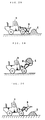
- the loader is moved forward in a condition in which a bucket B of the loader H is oriented toward a pile of earth E, so that the bucket B penetrates the pile of earth E.
- the bucket B is gradually moved to have its opening oriented upward as the loader H moves further forward. Namely, the bucket B is filled with earth E by such upward and forward motion. Then, as shown in Fig. 2B, the loader H travels to a desired place. When the loader H reaches the desired place, the opening of the bucket B is oriented downward to unload the earth E onto the place. After that, the loader H is moved slightly rearward to complete its digging operation.
- the present invention was made. Consequently, it is an object of the present invention to provide a method and apparatus for automating a routine operation of an electronically controlled hydraulic-powered machine, the apparatus being mounted on the hydraulic-powered machine to have the hydraulic-powered machine perform repetitively its simple routine operation by automation in safety, which routine operation is frequently required to be performed, and to have the hydraulic-powered machine perform an effective loading operation of a preset amount of load.
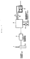
- Fig. 3 is a schematic block diagram of an embodiment of an apparatus for automating a routine operation of an electronically controlled hydraulic-powered machine.
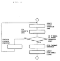
- a flowchart of operation performed by the embodiment of the apparatus of the present invention shown in Fig. 3 is shown in Fig. 4.
- Fig. 4 In this respect it also referred to co-pending European patent application No. 89 913 066.
- the reference numeral 11 denotes a control lever of a working equipment, for example such as that 20 shown in Fig. 5, the working equipment being mounted on the hydraulic-powered machine; and 12 an electric control unit for converting a motion of the control lever 11 operated by an operator into an electric signal V1 which is issued from the electric control unit 12 to an operation automating controller 131.
- the controller 131 issues a signal V2 to an electronic controller 15 upon receipt of the electric signal V1.
- the electronic controller 15 issues an electric signal V3 for controlling an electronically controlled hydraulic valve 16.
- pressure oil supplied by a hydraulic pump 19 passes through passage 17a or 17b so as to be supplied to a hydraulic actuator 18 such as hydraulic motors and hydraulic cylinders, whereby an actuating rod 18a of the hydraulic actuator 18 is actuated.
- the reference numeral 141 denotes a switchboard for selectively determining a mode M1, M2, M3, ..., M n of the automated routine operation of the working equipment mounted on the hydraulic-powered machine.
- the operator of the working equipment selects a mode of the automated routine operation of the working equipment by pushing a push button of the switchboard 141 so that the switchboard issues a signal for having the working equipment perform a desired frequently-required routine operation, for example such as a digging operation when the push button for the mode M1 is pushed or a earth discharging operation when the push button for the mode M2 is pushed.
- a desired frequently-required routine operation for example such as a digging operation when the push button for the mode M1 is pushed or a earth discharging operation when the push button for the mode M2 is pushed.
- the electric control unit 12 issues an electric signal to be summed in calculation.
- the flowchart shown in Fig. 4 comprises steps S01, S02, S03, S04 and S05.
- step S01 operation of the working equipment starts.
- step S02 the operator pushes a desired one of the push buttons or mode buttons M1, M2, M3, ..., M n of the switchboard 141 to select a desired mode of the routine operation.
- step S03 the operator pushes a push button 11a of the control lever 11 of the working equipment to have the working equipment perform the routine operation by automation.
- step S04 in order to correct the automated routine operation performed by the working equipment, the operator suitably operates the control lever 11 of the working equipment to have the electric control unit 12 issue an electric signal which is added to an automating signal in the step S05, which automating signal has the working equipment perform the routine operation by automation.
- the reference numeral 20 denotes the working equipment, for example such as electronically controlled hydraulic-powered digging machines and the like; and 21 a bucket employed in the working equipment 20.
- the working equipment or digging machine 20 is controlled in operation by an electronic controlling system of the second embodiment of the present invention shown in Fig. 5.
- mounted on the bucket 21 of the working equipment or digging machine 20 is a sensor 22 for measuring a loading weight of a load with which the bucket 21 is loaded.
- the first embodiment of the apparatus of the present invention shown in Figs. 5 and 6 differs from the embodiment shown in Figs. 3 and 4 in the following points:
- the operation automating controller 132 is electrically connected with the switchboard 142 which is provided with a plurality of workload switch buttons 14a and a plurality of data processing display units 14b, through which workload switch buttons 14a a workload is preset. Consequently, when the operator of the working equipment or digging machine 20 pushes a desired one of the workload switch buttons 14a, the thus specified workload is stored in a data area of the operation automating controller 132. Further inputted to the operation automating controller 132 each cycle of the routine operation performed by the working equipment or digging machine 20 is an actual workload data signal issued from the sensor 22 mounted on the bucket 21 of the working equipment or digging machine 20. Such actual workload data is accumulated in the operation automating controller 132.
- the operation automating controller 132 the actual workload data signal issued from the sensor 22 each cycle of the routine operation performed by the working equipment or digging machine 20 is summed up to produce a summed data signal which is compared with the predetermined data signal. Until the summed data signal coincides in amount with the predetermined data signal, a playback signal is issued from the operation automating controller 132 to the electronic controller 15 to have the electronically controlled hydraulic valve 16 permit the hydraulic pump 19 to supply the pressure oil to the hydraulic actuator 18 through the passage 17a or 17b, so that the actuator 18 performs repetitively its actuating operation, whereby the routine operation of the working equipment or digging machine 20 is repetitively performed by automation.
- the display units 14b display a condition in which the summed data signal coincides in amount with the predetermined data signal.
- the reference numeral 13a denotes a starting switch of the operation automating controller 132.
- Fig. 7 is a schematic block diagram of a second embodiment of the apparatus of the present invention for automating the routine operation of the electronically controlled hydraulic-powered machine.
- the second embodiment of the present invention shown in Figs. 7 and 8 differs from the embodiment shown in Figs. 3 and 4 in the following points.
- inputted to the operation automating controller 133 are: the electric signal V1 issued from the electric control unit 12; a switchboard signal issued from a dial-type switchboard 143 provided with a dial 14 c ; a warning signal issued from a warning switch 30; and a display switching panel signal issued from a dial-type display switching panel 31 provided with a dial 31a.
- the second embodiment of the present invention is provided with an external display unit 32.
- Fig. 8 is an electric circuit diagram of the operation automating controller 133 employed in the second embodiment of the apparatus of the present invention, illustrating an internal construction of the operation automating controller 133.
- the electric signal V1 corresponding to a motion of the control lever 11 operated by the operator is issued from the electric control unit 12 to the operation automating controller 133 in which the electric signal V1 is converted into a digital signal through an A/D converter.
- the thus converted digital signal is inputted to a CPU through which the digital signal is processed to produce a processed signal.
- the thus processed signal is then inputted to a D/A converter so as to be converted into an analog signal or electric signal V2.
- the processed signal is also stored in a RAM.
- the electric signal V2 issued from the D/A converter is supplied to the electronic controller 15 which in turn issues another electric signal V3 to control the electronically controlled hydraulic valve 16, so that the actuating rod 18a of the hydraulic actuator 18 is actuated as described above.
- the number of such storage operation performed in the RAM of the operation automating controller 133 is counted until the dial 14c reaches a position "off" or a position "P", so that the thus counted total number of the storage operation is multiplied by the predetermined time to obtain a product.
- Such product of the total number of the storage operation and the predetermined time constitutes a time a cycle or "cycle time" of the routine operation performed by the working equipment. Consequently, by setting the dial 31a of the display switching panel 31 at a position of the above "cycle time", it is possible for the operator to have the display unit 14b display the "cycle time".
- a solenoid 33 of the operation automating controller 133 is electrically energized to cause a movable contact 34 to be brought into contact with a fixed contact 35.
- the electric signal V1 stored in the RAM of the operation automating controller 133 is processed in the CPU and then converted into the signal V2 through the D/A converter, so that the signal V2 is supplied to the electronic controller 15 through the contacts 34, 35. Consequently, the electronic controller 15 issues the electric signal V3 to control the electronically controlled hydraulic valve 16, so that the actuating rod 18a of the hydraulic actuator 18 is actuated as described above.
- the external display unit 32 gives a warning to the other workers around the working equipment before the operator pushes the button 30a of the warning switch 30.
- a warning is issued by reducing intervals in energizing time of intermittently lightened warning lamp or by giving a warning sound issued from buzzers and the like.
- the operation automating controller 133 is provided with a counter for counting the number of the routine operation having been repetitively played back.
- the number of the routine operation having been played back by the working equipment by automation is displayed in the display unit 14b.
Landscapes
- Engineering & Computer Science (AREA)
- Mechanical Engineering (AREA)
- Mining & Mineral Resources (AREA)
- Civil Engineering (AREA)
- General Engineering & Computer Science (AREA)
- Structural Engineering (AREA)
- Operation Control Of Excavators (AREA)
Applications Claiming Priority (5)
| Application Number | Priority Date | Filing Date | Title |
|---|---|---|---|
| JP295334/88 | 1988-11-22 | ||
| JP29533488A JPH02142906A (ja) | 1988-11-22 | 1988-11-22 | 油圧駆動機械の作業自動化装置 |
| JP325963/88 | 1988-12-26 | ||
| JP32596388A JPH02171432A (ja) | 1988-12-26 | 1988-12-26 | 電子制御式油圧駆動掘削機械の作業自動化方法 |
| EP89913066A EP0406435B1 (de) | 1988-11-22 | 1989-11-22 | Verfahren und vorrichtung zum automatischen steuern einer elektronisch betätigten hydraulikbaumaschine |
Related Parent Applications (1)
| Application Number | Title | Priority Date | Filing Date |
|---|---|---|---|
| EP89913066.0 Division | 1989-11-22 |
Publications (2)
| Publication Number | Publication Date |
|---|---|
| EP0681067A2 true EP0681067A2 (de) | 1995-11-08 |
| EP0681067A3 EP0681067A3 (de) | 1996-02-14 |
Family
ID=26560213
Family Applications (2)
| Application Number | Title | Priority Date | Filing Date |
|---|---|---|---|
| EP95111844A Ceased EP0681067A3 (de) | 1988-11-22 | 1989-11-22 | Verfahren und Vorrichtung zur Automatisierung eines Routine-Arbeitsablaufs einer elektronisch gesteuerten Hydraulikbaumaschine. |
| EP89913066A Expired - Lifetime EP0406435B1 (de) | 1988-11-22 | 1989-11-22 | Verfahren und vorrichtung zum automatischen steuern einer elektronisch betätigten hydraulikbaumaschine |
Family Applications After (1)
| Application Number | Title | Priority Date | Filing Date |
|---|---|---|---|
| EP89913066A Expired - Lifetime EP0406435B1 (de) | 1988-11-22 | 1989-11-22 | Verfahren und vorrichtung zum automatischen steuern einer elektronisch betätigten hydraulikbaumaschine |
Country Status (5)
| Country | Link |
|---|---|
| US (1) | US5170342A (de) |
| EP (2) | EP0681067A3 (de) |
| KR (1) | KR0139797B1 (de) |
| DE (1) | DE68926911T2 (de) |
| WO (1) | WO1990005816A1 (de) |
Cited By (3)
| Publication number | Priority date | Publication date | Assignee | Title |
|---|---|---|---|---|
| EP0795651A1 (de) * | 1996-02-15 | 1997-09-17 | KABUSHIKI KAISHA KOBE SEIKO SHO also known as Kobe Steel Ltd. | Vorrichtung zum Steuern eines hydraulischen Baggers |
| WO1997046763A1 (de) * | 1996-06-03 | 1997-12-11 | Siemens Aktiengesellschaft | Verfahren und anordnung zur steuerung eines bewegungsablaufs bei einer fortbewegbaren landbearbeitungsmaschine |
| EP0816578A3 (de) * | 1996-06-26 | 1998-09-30 | Hitachi Construction Machinery Co., Ltd. | Frontsteuerungssystem, Bereichfestlegungsverfahren und Bedienungspaneel für Baumaschine |
Families Citing this family (22)
| Publication number | Priority date | Publication date | Assignee | Title |
|---|---|---|---|---|
| JP2525233B2 (ja) * | 1988-12-19 | 1996-08-14 | 株式会社小松製作所 | 作業機のティ―チング・プレイバック方法 |
| WO1991005113A1 (fr) * | 1989-09-26 | 1991-04-18 | Kabushiki Kaisha Komatsu Seisakusho | Installation automatisant le fonctionnement d'une machine a entrainement hydraulique |
| US5359517A (en) * | 1989-12-12 | 1994-10-25 | Kabushiki Kaisha Komatsu Seisakusho | Method and device for automating operation of construction machine |
| US5365442A (en) * | 1991-10-21 | 1994-11-15 | Thermedics, Inc. | Sonic ranging grade level controller |
| JP3126983B2 (ja) * | 1991-12-24 | 2001-01-22 | 日立建機株式会社 | 建設機械の油圧駆動装置 |
| EP0598937A1 (de) * | 1992-11-25 | 1994-06-01 | Samsung Heavy Industries Co., Ltd | Multiprozessorsystem für einen hydraulischen Bagger |
| EP0598936B1 (de) * | 1992-11-25 | 1999-08-25 | Samsung Heavy Industries Co., Ltd | Verfahren zur Steuerung eines Multitasking-fähigen Baggersystems |
| KR950001446A (ko) * | 1993-06-30 | 1995-01-03 | 경주현 | 굴삭기의 자동 반복작업 제어방법 |
| US5845223A (en) * | 1993-07-02 | 1998-12-01 | Samsung Heavy Industry Co., Ltd. | Apparatus and method for controlling actuators of hydraulic construction equipment |
| JPH07268897A (ja) * | 1994-03-23 | 1995-10-17 | Caterpillar Inc | 自己適合性掘削制御システムとその方法 |
| US5446980A (en) * | 1994-03-23 | 1995-09-05 | Caterpillar Inc. | Automatic excavation control system and method |
| US5493798A (en) * | 1994-06-15 | 1996-02-27 | Caterpillar Inc. | Teaching automatic excavation control system and method |
| KR100328217B1 (ko) * | 1996-04-30 | 2002-06-26 | 볼보 컨스트럭션 이키프먼트 홀딩 스웨덴 에이비 | 유압식건설기계의자동진동장치및방법 |
| KR100328218B1 (ko) * | 1996-04-30 | 2002-06-26 | 볼보 컨스트럭션 이키프먼트 홀딩 스웨덴 에이비 | 유압식건설기계의조작방식선택장치및방법 |
| US6025686A (en) * | 1997-07-23 | 2000-02-15 | Harnischfeger Corporation | Method and system for controlling movement of a digging dipper |
| US6278955B1 (en) | 1998-12-10 | 2001-08-21 | Caterpillar Inc. | Method for automatically positioning the blade of a motor grader to a memory position |
| US6286606B1 (en) | 1998-12-18 | 2001-09-11 | Caterpillar Inc. | Method and apparatus for controlling a work implement |
| US6615114B1 (en) | 1999-12-15 | 2003-09-02 | Caterpillar Inc | Calibration system and method for work machines using electro hydraulic controls |
| US8360180B2 (en) * | 2007-12-31 | 2013-01-29 | Caterpillar Inc. | System for controlling a hybrid energy system |
| US8989971B2 (en) * | 2008-05-27 | 2015-03-24 | Eaton Corporation | Method and apparatus for detecting and compensating for pressure transducer errors |
| DE112016000037B4 (de) * | 2016-03-28 | 2020-04-02 | Komatsu Ltd. | Bewertungsvorrichtung und Bewertungsverfahren |
| CN107282896A (zh) * | 2017-07-16 | 2017-10-24 | 佛山市恒学科技服务有限公司 | 一种冷芯盒射芯机取模装置控制系统 |
Citations (1)
| Publication number | Priority date | Publication date | Assignee | Title |
|---|---|---|---|---|
| JPS62244931A (ja) | 1986-04-15 | 1987-10-26 | Komatsu Ltd | 建設機械の操作応答特性制御装置 |
Family Cites Families (13)
| Publication number | Priority date | Publication date | Assignee | Title |
|---|---|---|---|---|
| US3487958A (en) * | 1968-01-31 | 1970-01-06 | Caterpillar Tractor Co | Self-cycling loader |
| JPS51101303A (en) * | 1975-03-04 | 1976-09-07 | Toyo Umpanki Co Ltd | Pawaashoberuno jidokutsusakusochi |
| JPS5851096B2 (ja) * | 1976-06-07 | 1983-11-14 | 株式会社小松製作所 | シヨベル系車輛による運土車輛に対する積込み回数制御装置 |
| US4715012A (en) * | 1980-10-15 | 1987-12-22 | Massey-Ferguson Services N.V. | Electronic tractor control |
| FR2510278A1 (en) * | 1981-07-24 | 1983-01-28 | Mannesmann Ag | Automatic control system for hydraulic excavator - uses calculator with memory to store manual movement for subsequent automatic control operations through electrohydraulic valves |
| JPS58160437A (ja) * | 1982-03-17 | 1983-09-22 | Kubota Ltd | シヨベル作業車 |
| JPS5998935A (ja) * | 1982-11-30 | 1984-06-07 | Kawasaki Heavy Ind Ltd | シヨベルロ−ダの作業率教示装置 |
| KR910002234B1 (ko) * | 1982-12-01 | 1991-04-08 | 히다찌 겡끼 가부시기가이샤 | 적하 이송장치의 적하중량 표시장치 |
| JPS59206535A (ja) * | 1983-05-09 | 1984-11-22 | Hitachi Constr Mach Co Ltd | 油圧シヨベルの積荷重量表示装置 |
| JPS59195938A (ja) * | 1983-04-20 | 1984-11-07 | Hitachi Constr Mach Co Ltd | 油圧シヨベルの直線掘削制御装置 |
| JPH0671891B2 (ja) * | 1983-06-24 | 1994-09-14 | 株式会社小松製作所 | 履帯式トラクタの制御装置 |
| US4742468A (en) * | 1986-06-16 | 1988-05-03 | Yamate Industrial Co., Ltd. | Lift truck control system |
| US4949263A (en) * | 1987-06-01 | 1990-08-14 | Alert-O-Brake Systems Inc. | Load handling vehicle monitoring system |
-
1989
- 1989-11-22 WO PCT/JP1989/001195 patent/WO1990005816A1/ja not_active Ceased
- 1989-11-22 EP EP95111844A patent/EP0681067A3/de not_active Ceased
- 1989-11-22 DE DE68926911T patent/DE68926911T2/de not_active Expired - Fee Related
- 1989-11-22 EP EP89913066A patent/EP0406435B1/de not_active Expired - Lifetime
- 1989-11-22 KR KR1019900701568A patent/KR0139797B1/ko not_active Expired - Fee Related
- 1989-11-22 US US07/548,880 patent/US5170342A/en not_active Expired - Lifetime
Patent Citations (1)
| Publication number | Priority date | Publication date | Assignee | Title |
|---|---|---|---|---|
| JPS62244931A (ja) | 1986-04-15 | 1987-10-26 | Komatsu Ltd | 建設機械の操作応答特性制御装置 |
Cited By (4)
| Publication number | Priority date | Publication date | Assignee | Title |
|---|---|---|---|---|
| EP0795651A1 (de) * | 1996-02-15 | 1997-09-17 | KABUSHIKI KAISHA KOBE SEIKO SHO also known as Kobe Steel Ltd. | Vorrichtung zum Steuern eines hydraulischen Baggers |
| WO1997046763A1 (de) * | 1996-06-03 | 1997-12-11 | Siemens Aktiengesellschaft | Verfahren und anordnung zur steuerung eines bewegungsablaufs bei einer fortbewegbaren landbearbeitungsmaschine |
| EP0816578A3 (de) * | 1996-06-26 | 1998-09-30 | Hitachi Construction Machinery Co., Ltd. | Frontsteuerungssystem, Bereichfestlegungsverfahren und Bedienungspaneel für Baumaschine |
| US6169948B1 (en) | 1996-06-26 | 2001-01-02 | Hitachi Construction Machinery Co., Ltd. | Front control system, area setting method and control panel for construction machine |
Also Published As
| Publication number | Publication date |
|---|---|
| EP0681067A3 (de) | 1996-02-14 |
| EP0406435A4 (en) | 1993-12-15 |
| KR0139797B1 (ko) | 1999-03-30 |
| DE68926911T2 (de) | 1996-12-12 |
| EP0406435A1 (de) | 1991-01-09 |
| DE68926911D1 (de) | 1996-09-05 |
| WO1990005816A1 (fr) | 1990-05-31 |
| EP0406435B1 (de) | 1996-07-31 |
| KR900702151A (ko) | 1990-12-06 |
| US5170342A (en) | 1992-12-08 |
Similar Documents
| Publication | Publication Date | Title |
|---|---|---|
| EP0681067A2 (de) | Verfahren und Vorrichtung zur Automatisierung eines Routine-Arbeitsablaufs einer elektronisch gesteuerten Hydraulikbaumaschine | |
| EP0604402B1 (de) | Vorrichtung zum Halten der Schaufelstellung eines Ladefahrzeuges | |
| US5274557A (en) | Teaching and playback method for work machine | |
| US4934463A (en) | Automatic implement position control system | |
| EP0334959B2 (de) | Gerät zur messung des ladegewichts auf einem baufahrzeug | |
| EP0667451B1 (de) | Regelungsanordnung einer hydraulischen pumpe für baumaschinen | |
| US5359517A (en) | Method and device for automating operation of construction machine | |
| KR950009324B1 (ko) | 액츄에이터 작동속도 자동조절장치 및 그 제어방법 | |
| US5629849A (en) | Method for controlling operation of repeated work of excavator vehicle | |
| DE19651594A1 (de) | Vorrichtung und Verfahren zum automatischen Rütteln von Arbeitsteilen von Motorbaufahrzeugen | |
| GB2252642A (en) | System for automatically controlling operation of construction vehicle | |
| EP1126087B1 (de) | Steuervorrichtung eines hydraulischen kreislaufs einer baumaschine | |
| JPS595166B2 (ja) | ポンプ制御油圧回路の制御方法 | |
| JPH09296482A (ja) | 油圧式建設機械の操作方式選択装置及び方法 | |
| US6459976B1 (en) | Method and system for controlling steady-state speed of hydraulic cylinders in an electrohydraulic system | |
| JPH0336971B2 (de) | ||
| EP0526639A1 (de) | Schildhöhensteuerungsvorrichtung für kettenfahrzeuge | |
| JP2726997B2 (ja) | 建設機械の作業自動化装置 | |
| JPS5826128A (ja) | 腕式作業機のバケツト角制御方法 | |
| US5796174A (en) | Device for controlling breaker in construction vehicles | |
| JPS63312432A (ja) | 旋回体の制動制御装置 | |
| JP2847649B2 (ja) | 操作レバーの制御方法 | |
| KR100256775B1 (ko) | 유압식 건설기계의 제어장치 및 제어방법 | |
| JPH04353130A (ja) | 油圧作業機械における作業装置の振動抑制制御装置 | |
| JPH01223225A (ja) | 油圧機械の制御装置 |
Legal Events
| Date | Code | Title | Description |
|---|---|---|---|
| PUAI | Public reference made under article 153(3) epc to a published international application that has entered the european phase |
Free format text: ORIGINAL CODE: 0009012 |
|
| AC | Divisional application: reference to earlier application |
Ref document number: 406435 Country of ref document: EP |
|
| AK | Designated contracting states |
Kind code of ref document: A2 Designated state(s): DE GB SE |
|
| PUAL | Search report despatched |
Free format text: ORIGINAL CODE: 0009013 |
|
| AK | Designated contracting states |
Kind code of ref document: A3 Designated state(s): DE GB SE |
|
| 17P | Request for examination filed |
Effective date: 19960208 |
|
| GRAG | Despatch of communication of intention to grant |
Free format text: ORIGINAL CODE: EPIDOS AGRA |
|
| 17Q | First examination report despatched |
Effective date: 19980729 |
|
| STAA | Information on the status of an ep patent application or granted ep patent |
Free format text: STATUS: THE APPLICATION HAS BEEN REFUSED |
|
| 18R | Application refused |
Effective date: 19990108 |