EP0685983A2 - Magnetische Schaltung für Lautsprecher und Verfahren zu ihrer Herstellung - Google Patents
Magnetische Schaltung für Lautsprecher und Verfahren zu ihrer Herstellung Download PDFInfo
- Publication number
- EP0685983A2 EP0685983A2 EP95108259A EP95108259A EP0685983A2 EP 0685983 A2 EP0685983 A2 EP 0685983A2 EP 95108259 A EP95108259 A EP 95108259A EP 95108259 A EP95108259 A EP 95108259A EP 0685983 A2 EP0685983 A2 EP 0685983A2
- Authority
- EP
- European Patent Office
- Prior art keywords
- top plate
- magnet
- circuit unit
- magnetic circuit
- anisotropic
- Prior art date
- Legal status (The legal status is an assumption and is not a legal conclusion. Google has not performed a legal analysis and makes no representation as to the accuracy of the status listed.)
- Granted
Links
Images


Classifications
-
- H—ELECTRICITY
- H04—ELECTRIC COMMUNICATION TECHNIQUE
- H04R—LOUDSPEAKERS, MICROPHONES, GRAMOPHONE PICK-UPS OR LIKE ACOUSTIC ELECTROMECHANICAL TRANSDUCERS; ELECTRIC HEARING AIDS; PUBLIC ADDRESS SYSTEMS
- H04R9/00—Transducers of moving-coil, moving-strip, or moving-wire type
- H04R9/02—Details
- H04R9/025—Magnetic circuit
-
- H—ELECTRICITY
- H04—ELECTRIC COMMUNICATION TECHNIQUE
- H04R—LOUDSPEAKERS, MICROPHONES, GRAMOPHONE PICK-UPS OR LIKE ACOUSTIC ELECTROMECHANICAL TRANSDUCERS; ELECTRIC HEARING AIDS; PUBLIC ADDRESS SYSTEMS
- H04R9/00—Transducers of moving-coil, moving-strip, or moving-wire type
- H04R9/06—Loudspeakers
-
- H—ELECTRICITY
- H04—ELECTRIC COMMUNICATION TECHNIQUE
- H04R—LOUDSPEAKERS, MICROPHONES, GRAMOPHONE PICK-UPS OR LIKE ACOUSTIC ELECTROMECHANICAL TRANSDUCERS; ELECTRIC HEARING AIDS; PUBLIC ADDRESS SYSTEMS
- H04R31/00—Apparatus or processes specially adapted for the manufacture of transducers or diaphragms therefor
- H04R31/006—Interconnection of transducer parts
-
- Y—GENERAL TAGGING OF NEW TECHNOLOGICAL DEVELOPMENTS; GENERAL TAGGING OF CROSS-SECTIONAL TECHNOLOGIES SPANNING OVER SEVERAL SECTIONS OF THE IPC; TECHNICAL SUBJECTS COVERED BY FORMER USPC CROSS-REFERENCE ART COLLECTIONS [XRACs] AND DIGESTS
- Y10—TECHNICAL SUBJECTS COVERED BY FORMER USPC
- Y10T—TECHNICAL SUBJECTS COVERED BY FORMER US CLASSIFICATION
- Y10T29/00—Metal working
- Y10T29/49—Method of mechanical manufacture
- Y10T29/49002—Electrical device making
- Y10T29/49005—Acoustic transducer
Definitions
- This invention relates to a magnetic circuit unit and a method of manufacturing the same.
- this invention relates to a magnetic circuit unit for a loud-speaker.
- FIG. 9 A configuration of a conventional magnetic circuit unit for a loud-speaker is shown in FIG. 9.
- This magnetic circuit unit for a loud-speaker comprises a top plate 2, a sintered magnet 7, and an outer yoke 3.
- the sintered magnet 7 is magnetized in an axial direction, and its magnetic flux is made to concentrate toward a magnetic pole gap 8 by the top plate 2.
- This type of loud-speaker is used for a thin portable radio, or in the field of movable communication for a portable telephone etc., and the demand for this loud-speaker is increasing rapidly.
- Nd-Fe-B system magnet is apt to rust easily, it is indispensable to apply an anti-corrosive treatment, and various treating methods have been proposed.
- cation electrodeposition is an excellent anti-corrosive treatment, but the problem with this method is that the equipment cost for temperature control is extremely high.
- a wet anticorrosive treated film is also proposed, but there was no method which can accomplish a uniformly formed coat with satisfaction in a complicated magnetic circuit unit.
- Another object of this invention is to provide a method of manufacturing the same.
- a first magnetic circuit unit for a loud-speaker of this invention comprises a top plate which is integrated with an anisotropic Nd-Fe-B system magnet on one side of the top plate, wherein the top plate has a hollow part whose inner surface is bonded to the anisotropic Nd-Fe-B system magnet through Joule heating by passing a current under compression, and an anticorrosive coating is formed on the surface of the unit.
- the hollow part of the top plate is formed in the shapes of cone, column, truncated cone, or partial sphere.
- the anti-corrosive coating comprises an acrylic resin anti-corrosive coating with a thickness of 7 to 15 ⁇ m.
- a second magnetic circuit unit for a loud-speaker of this invention comprises a top plate which is integrated with an anisotropic Nd-Fe-B system magnet on one side of the top plate, wherein the top plate has a hollow part whose inner surface is bonded to the anisotropic Nd-Fe-B system magnet through Joule heating by passing a current under compression, and a magnetic circuit unit which is bonded with a loop anisotropic Nd-Fe-B system magnet at a looped yoke is disposed at the outer circumference of the unit, and an anti-corrosive coating is formed on the surface of the unit.
- a magnetic circuit unit is provided with a magnetic circuit bonded with a loop anisotropic Nd-Fe-B magnet at a looped yoke in the outer circumference, that the hollow part of the top plate is formed in the shapes of cone, column, truncated cone, or partial sphere.
- the anti-corrosive coating comprises an acrylic resin anti-corrosive coating with a thickness of 7 to 15 ⁇ m.
- a loud-speaker comprises a magnetic circuit unit of the above-mentioned first and second configurations.
- a method of manufacturing a magnetic circuit unit for a loud-speaker of this invention comprising a top plate which is integrated with an anisotropic Nd-Fe-B system magnet on one side of the top plate, comprises the steps of magnetically orienting the top plate disposed with a hollow part and anisotropic Nd-Fe-B system magnet powder inside a forming die, integrated bonding through Joule heating by passing a current under compression, adhering the integrated compact to an outer yoke, adhering a loop anisotropic Nd-Fe-B system magnet to a looped yoke, and forming an anti-corrosive coating thereon.
- the step of integrated bonding through Joule heating by passing a current under compression is performed under a forming pressure of 100 to 200 kgf/cm2.
- the forming die is cooled to a temperature below 100°C while maintaining the pressure, and the integrated compact is then taken out from the forming die.
- a method of forming the anti-corrosive coating comprises the steps of dipping in an acrylic resin emulsion, coating by means of a rotary coating device, and drying and hardening to form a coating with a thickness of 7 to 15 ⁇ m.
- steps comprising adhering a loop anisotropic magnet to a looped yoke and adhering the loop anisotropic magnet to the outer yoke are performed after the step of adhering the integrated compact to an outer yoke and before the step of forming an anti-corrosive coating thereon.
- the inner surface of the hollow part in the top plate and the anisotropic Nd-Fe-B system magnet are bonded integrally through Joule heating by passing a current under compression, and the surface is covered with an anti-corrosive coating, so that an adhesion step can be reduced or omitted, magnetic flux density can be improved without reducing a width of uniform magnetic field in a magnetic pole gap, and a durable anti-corrosive treatment can be performed at low price, thereby attaining higher performance and lower cost for the loud-speaker.
- the hollow part into the shapes of cone, column, truncated cone, and partial sphere assures the bonding between the top plate and the anisotropic Nd-Fe-B system magnet.
- magnetic flux density can be improved without reducing a width of uniform magnetic field in a magnetic pole gap, so that a magnetic circuit unit for a loud-speaker can be obtained, which has a smaller size, higher performance and reduced cost.
- the preferable configuration in that the anti-corrosive coating comprises an acrylic resin anti-corrosive coating with a thickness of 7 to 15 ⁇ m enables the carrying out of a durable anti-corrosive treatment at low price, improving performance, and reducing the cost of a loud-speaker.
- the inner surface of the hollow part in the top plate and the anisotropic Nd-Fe-B system magnet are bonded through Joule heating by passing a current under compression, the magnetic circuit which is bonded to a loop anisotropic Nd-Fe-B system magnet at a looped yoke is disposed in the circumference, and an anti-corrosive coating is formed on the surface.
- the adhesion step can be reduced or omitted, deterioration of magnetic properties due to thinner formation can be improved, and a durable anti-corrosive treatment can be performed at low price, thereby attaining a magnetic circuit unit for a loud-speaker which enables a thinner form, higher performance, and lower cost for a loud-speaker.
- a magnetic circuit unit for a loud-speaker wherein the top plate has a hollow part whose inner surface is bonded to the anisotropic Nd-Fe-B system magnet through Joule heating by passing a current under compression, and a magnetic circuit which is bonded with a loop anisotropic Nd-Fe-B system magnet at a looped yoke is disposed in the outer circumference, forming the hollow part into the shapes of cone, column, truncated cone, and partial sphere assures the bonding between the top plate and the anisotropic Nd-Fe-B system magnet, and magnetic flux density can be improved without reducing a width of uniform magnetic field in a magnetic pole gap. In this way, a magnetic circuit unit for a loud-speaker can be obtained which enables a smaller size, higher performance and reduced cost for a loud-speaker.
- the manufacturing method of this invention comprises the steps of magnetically orienting the top plate disposed with a hollow part and anisotropic Nd-Fe-B system magnet powder inside a forming die, integrated bonding through Joule heating, and forming an anti-corrosive coating thereon.
- the adhesion step can be reduced or omitted, and as a result, the equipment cost and the manufacturing cost can be reduced.
- magnetic efficiency can be enhanced, so a magnetic circuit unit for a loud-speaker which has improved magnetic performance and anti-corrosive property can be attained.
- the forming die is cooled to a temperature below 100°C while maintaining the pressure, and the compact is then taken out from the forming die. In this way, the bonding can be stabilized, and occurrence of cracks etc. can be prevented.
- the preferable method of forming an anti-corrosive coating comprises the steps of dipping in an acrylic resin emulsion, coating by means of a rotary coating device, and drying and hardening to form a coating with a thickness of 7 to 15 ⁇ m.
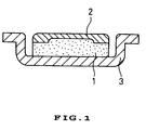
- FIG. 1 is a cross-sectional view showing an integrated magnetic circuit unit in a first embodiment of this invention.
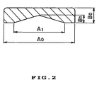
- FIG. 2 is a cross-sectional view showing a top plate having a conical hollow part which is useful in this invention.
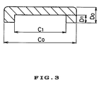
- FIG. 3 is a cross-sectional view showing a top plate having a columnar hollow part which is useful in this invention.
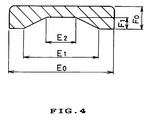
- FIG. 4 is a cross-sectional view showing a top plate having a truncated conical hollow part which is useful in this invention.
- FIG. 5 is a cross-sectional view showing a top plate having a partially spherical hollow part which is useful in this invention.
- FIG. 6 is a cross-sectional view showing an integrated magnetic circuit unit covered with an anti-corrosive coating in a first embodiment of this invention.
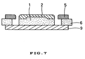
- FIG. 7 is a cross-sectional view showing a magnetic circuit unit in a second embodiment of this invention.
- FIG. 8 is a partial cross-sectional view schematically showing a method of bonding through Joule heating by passing a current under compression.
- FIG. 9 is a cross-sectional view showing a conventional magnetic circuit unit for a loud-speaker.
- a magnetic circuit unit for a loud-speaker of this invention is comprised of a Nd-Fe-B system magnet which is formed through Joule heating by passing a current under compression, a top plate having a hollow part which is integrated with this magnet, and an outer yoke or a looped yoke.
- the top plate comprises a material with high permeability such as an electromagnetic steel plate or a silicon steel plate.
- An anisotropic Nd-Fe-B system magnet is used as the magnet which is formed through Joule heating by passing a current under compression.
- acrylic emulsion resin examples include emulsions containing a resin whose monomer is selected from the group consisting of methacrylate ester, ester acrylate, methacrylic acid, acrylic acid, or derivatives etc. thereof. Styrene and butadiene etc. may be contained in this resin, and those containing a cross-linking initiator are used.
- the top plate and the magnet are integrated by directly bonding the anisotropic Nd-Fe-B system magnet and the top plate disposed with a hollow part through Joule heating. Subsequently, a uniform anti-corrosive coating is formed with acrylic emulsion resin.
- the anti-corrosive coating comprising acrylic emulsion resin is formed by a curing reaction after coating. This anticorrosive coating itself of acrylic emulsion resin is generally well known.
- a magnetic circuit unit obtained in this way allows the reduction or omission of an adhesion step, and magnetic properties are improved due to enhancement of magnetic efficiency, and furthermore, the anti-corrosive treatment is inexpensive and perfect, which contributes to higher performance and lower cost for the loud-speaker.
- a method of forming through Joule heating used in this invention is a method which is already developed as a manufacturing method of a Nd-Fe-B system magnet (M. Wada and Yamashita: New method of making Nd-Fe-B full dense magnets. IEEE. Trans. Magn. MAG-26, No.5, p.2601 (1990)). This method will be explained now more in detail.
- This method comprises the steps of processing magnet powder as such through direct discharge inside a forming die cavity for activation, compressing through pressure, raising the temperature rapidly through Joule heating by passing a current and allowing plastic deformation to take place by pressure, and attaining a complete bulk of the magnet powder when atoms are bonded by dispersion at their interfaces.
- FIG. 8 A structure of the main part is shown in FIG. 8.
- a die 11 was made of non-conductive ceramics, and Syalon (Si-Al-O-N system) was mainly used.
- Electrodes 12, 12' comprising graphite mounted with WCCo at edge parts 13, 13' serve also as punch.
- a space which exists between the die 11 and the electrodes 12, 12' comprised a cavity, and magnet powder 14 was filled into the cavity.
- the upper and lower electrodes 12, 12' were provided with pressure from pressure rods P, P', and via these pressure rods P, P', the electrodes 12, 12' were connected to a discharge processing source 15 and a Joule heating source 16 which can be switched.
- the die 11 and the elecrodes 12, 12' are stored inside a vacuum chamber, and the inside of the cavity can be vacuumed.
- magnet powder is filled into the cavity, and the atmosphere is vacuumed to 10 ⁇ 1 to 10 ⁇ 3 torr, and then, necessary compression pressure is provided between the electrodes 12, 12'.
- a DC pulse current is passed between the electrodes 12, 12' in this state to perform discharge processing (for example, for about 40 seconds), and then by providing a DC constant current (e.g., electric current density 300A/cm2), the temperature was raised rapidly through Joule heating.
- a DC constant current e.g., electric current density 300A/cm2
- this method was applied to form a magnet for a loud-speaker, so in this case, the magnet powder and the top plate were placed simultaneously into the cavity to integrate the top plate and the magnet.
- FIG. 1 is a cross-sectional view showing an integrated magnetic circuit unit in a first embodiment.
- reference numeral 1 represents a magnet which is formed through Joule heating by passing a current under compression
- 2 represents a top plate
- 3 represents an outer yoke.
- An anisotropic Nd-Fe-B system magnet is used as the magnet 1 which is formed through Joule heating, and this magnet 1 is bonded to an inner surface of a hollow part formed on one side of the top plate 2 through Joule heating by passing a current under compression, thereby integrating the two parts. It is preferable to respectively determine a thickness of the top plate 2 to be from 0.3 to 0.8 mm and a diameter to be from 8 to 13 mm.
- FIG. 2 is a cross-sectional view showing an example of the top plate 2 having a conical hollow part.
- the dimension of a hollow part A1 to be from 0.8 A0 to A0 and a dimension of B1 to be from 0.4 B0 to 0.5 B0.
- This shape of the hollow part is characterized in that the thickness in the central part of the magnet is thicker than in an example in which a columnar magnet is integrated with a top plate without a hollow part. As a result of that, magnetic permeance in this particular part increases, and therefore, thermal demagnetization can be reduced.
- FIG. 3 is a cross-sectional view showing an example of the top plate 2 having a columnar hollow part.
- a dimension of a hollow part C1 to be from 0.8 C0 to 0.9 C0 and a dimension of D1 to be from 0.4 D0 to 0.5 D0.
- This shape of the hollow part is characterized in that this shape can attain an utmost magnet volume without reducing a surface area on the side of the top plate 2.
- a maximum value of magnetic flux density in a magnetic pole gap improves, but the tone quality as a loud-speaker deteriorates due to a reduction of a width of uniform magnetic field.
- this embodiment enables the improvement of magnetic flux density in a magnetic pole gap by about 10 % as compared with an example using a top plate without a hollow part.
- FIG. 4 is a cross-sectional view showing an example of the top plate 2 having a truncated conical hollow part.
- a dimension of a hollow part E1 to be from 0.8 E0 to 0.9 E0
- a dimension of E2 to be from 0.4 E0 to 0.5 E0
- a dimension of F1 to be from 0.4 F0 to 0.5 F0.
- This shape is characterized by combining a taper with a flat surface part, so that a punch used for processing the hollow part of the top plate can be removed easily from workpiece, which results in a long life-time of punch.
- the magnetic properties are of the same level as that in other shapes.
- FIG. 5 is a cross-sectional view showing an example of the top plate 2 having a partially spherical hollow part.
- a dimension of a hollow part G1 to be from 0.8 G0 to G0 and a dimension of H1 to be from 0.4 H0 to 0.5 H0.
- This shape is characterized by its spherical surface, which enables the easy removal of a punch and easy processing. It goes without saying that the magnetic properties are of the same level as that in other shapes.
- a top plate was placed inside a forming die used for Joule heating by passing a current under compression, and anisotropic neodymium-iron-boron system magnet powder was put into the same forming die.
- This magnet powder was manufactured by upsetting a hot-forming body made of melt spun powder of Nd-Fe-B system alloy and then powdering by means of a hydrogen decrepitation method.
- the magnet powder comprised particles having an average size of 150 ⁇ m.
- Joule heating by passing a current was conducted.
- the Joule heating was performed in an inactive gas while providing a pressure of 150 kgf/cm2.
- the temperature of the forming die at this moment is preferably from 700 to 750°C.
- Electric power to pass a current is preferably about 15 V and 250 A.
- the forming die was cooled to 80°C while maintaining the pressure, and the compact was then taken out from the forming die.
- the compact was cooled to room temperature in dry air containing a volatile corrosion inhibitor with 0.4 to 0.7 ppm concentration (e.g., the product of the firm KYOEISHA KAGAKU CO., LTD. under the trade name of "RASMIN V-7".
- a volatile corrosion inhibitor e.g., the product of the firm KYOEISHA KAGAKU CO., LTD. under the trade name of "RASMIN V-7".
- An integrated product comprising a disk-form magnet, for example, having a diamter of 13 mm and a thickness of 1.3 mm bonded integrally with a top plate of 13 mm in diameter and 0.8 mm thick, was manufactured according to the above-mentioned method and an outer yoke was adhered thereto to form a magnetic circuit unit.
- a loud-speaker was built by using the above-mentioned magnetic circuit unit, and after being pulse-magnetized, it was confirmed that the loud-speaker had a desired sound pressure and frequency characteristics. For example, the sound pressure was 84 dB. Furthermore, in this magnetic circuit unit, the top plate and the magnet were firmly bonded together, so no damage was sustained in a dropping test.
- the magnet powder contacting an electromagnetic steel plate of the top plate was pressed under compression, and in this state, a large current was passed into this contact part. Since contact resistance is large, Joule heat is generated rapidly to heat up this contact part to a high temperature, so that it is anticipated that a strong bonding is accomplished by atoms dispersing in the magnet powder and in the electromagnetic steel plate.
- Nd-Fe-B system magnet powder is softened at a temperature higher than about 600°C, so that deformation takes place under the compression pressure to increase a contact part with the electromagnetic steel plate.
- the magnet powder is molded together along a hollow part of the top plate without a gap, and atomic dispersion occurring at the bonded part of the magnet powder attains a strong bonding, thereby forming a bulk magnet.
- An adhesive layer is not present between the top plate and the magnet formed by Joule heating, and they are directly bonded to each other. As a result, magnetic resistance of a conventional adhesive layer does not interfere with a flow of magnetic flux, which results in an increase of magnetic flux density in the magnetic pole gap.
- a magnetic circuit unit was manufactured according to the same method described in Example 1 except for using a top plate which does not have a hollow part on one side, and an anticorrosive coating was formed.
- this magnetic circuit unit was valued as a loud-speaker, it became clear that this comparative example had 0.5 dB lower sound pressure than that of Example 1.
- a magnetic circuit unit was manufactured according to the same method described in Example 1 except for using a temperature exceeding 100°C for cooling a forming die while maintaining the pressure. As a result, cracks were formed on a face bonding the top plate and the magnet.
- a magnetic circuit unit was manufactured according to the same method described in Example 1 except for determining the forming pressure during Joule heating by passing a current to be below 100 kgf/cm2 and exceeding 200 kgf/cm2. As a result, when the forming pressure was below 100 kgf/cm2, the top plate and the magnet were not bonded satisfactorily, and when the forming pressure exceeded 200 kgf/cm2, the coercive force of the magnet deteriorated by 15 % in comparison to Example 1.
- FIG. 7 A second embodiment of this invention will be explained by referring to FIG. 7.
- FIG. 7 is a cross-sectional view showing a main part of a magnetic circuit unit in a second embodiment.
- 1 represents a magnet which is formed through Joule heating by passing a current under compression
- 2 represents a top plate
- 5 represents a looped yoke
- 6 represents a loop anisotropic Nd-Fe-B system magnet
- 9 represents an outer flat yoke.
- An anisotropic Nd-Fe-B system magnet was used as the magnet 1 which is formed through Joule heating, and this magnet 1 is bonded integrally to an inner surface of a hollow part formed on one side of the top plate 2 through Joule heating, thereby integrating the two parts.
- a magnetic circuit unit comprising the loop anisotropic Nd-Fe-B system magnet 6 bonded to the looped yoke 5 is positioned.
- the thickness of the top plate 2 is from 0.3 to 0.8 mm and the diameter to be from 8 to 13 mm.
- the thickness of the looped yoke 5 is preferably determined to be from 0.3 to 0.8 mm, the outer diameter to be from 18 to 22 mm, and the inner diameter to be from 9 to 14 mm.
- the thickness of the outer flat yoke 9 is preferably determined to be from 0.3 to 0.8 mm and the diameter to be from 18 to 22 mm.
- the magnet 1 and the top plate 2 were integrated, and the loop anisotropic Nd-Fe-B system magnet 6 was bonded to the looped yoke 5, which is followed by adhering them on the outer flat yoke 9 in a position shown in FIG. 7.
- a magnetic circuit unit was manufactured in this way, and a uniform anti-corrosive coating was formed thereon.
- This magnetic circuit unit was manufactured by using, for example, an integrated product comprising a columnar magnet having a diameter of 13 mm and a thickness of 1.3 mm bonded with a top plate of 13 mm in diameter and 0.8 mm thick, and by respectively adhering a product comprising a loop anisotropic Nd-Fe-B system magnet having an outer diameter of 19 mm, an inner diameter of 15 mm, and a thickness of 1.3 mm attached to a looped yoke having an outer diameter of 18 mm, an. inner diameter of 14 mm, and a thickness of 0.8 mm onto an outer flat yoke formed with a diameter of 18 mm and a thickness of 0.8 mm.
- the columnar magnet in the above-mentioned magnetic circuit unit was magnetized in an axial direction, and after the loop anisotropic Nd-Fe-B system magnet was magnetized in a reverse axial direction, magnetic flux density in a magnetic pole gap was measured.
- the maximum value of the magnetic flux density was 8.7 kG, which made clear that the magnetic flux density improved by 20 % versus an example which does not use a loop anisotropic Nd-Fe-B system magnet.
- a magnet material used in this invention belongs to an anisotropic neodymium-iron-boron system magnet.
- a magnet material which contains an additive for the improvement of temperature characteristics such as gallium, zirconium, hafnium, and titanium, may be used.
- an anisotropic Nd-Fe-B system magnet powder manufactured by an HDDR method Hydrophilic - Decomposition - Desorption Recombination method.
- this invention is superior to the conventional system.
- contraction during sintering was so great in the manufacturing process of a sintered magnet, that it was difficult to obtain a small magnet with dimensional accuracy.
- the magnet must be ground, and the cost of grinding was comparatively higher than that for a large magnet. Therefore, as the size becomes smaller, the magnetic circuit unit becomes expensive even though the amount of magnet used is less.
- the magnet which is formed through Joule heating by passing a current under compression of this invention is formed through Joule heating inside a forming die, so that the dimensional accuracy is excellent and grinding is no longer necessary.
- this invention enables an integrated bonding of a magnet with a top plate, an outer yoke etc.
- this invention provides an integrated bonding of a top plate and a magnet, so that a top plate disposed with a hollow shape can be used regardless of a shape of a bonding face.
- a loop anisotropic Nd-Fe-B system magnet in the outer circumference, magnetic properties can be improved.
- determining manufacturing conditions specifically enables automation of the steps of Joule heating and anti-corrosive treatment, which can contribute to a cost reduction. It goes without saying that this magnetic circuit unit is also applicable for a micromotor.
Landscapes
- Physics & Mathematics (AREA)
- Engineering & Computer Science (AREA)
- Acoustics & Sound (AREA)
- Signal Processing (AREA)
- Audible-Bandwidth Dynamoelectric Transducers Other Than Pickups (AREA)
- Hard Magnetic Materials (AREA)
Applications Claiming Priority (6)
| Application Number | Priority Date | Filing Date | Title |
|---|---|---|---|
| JP11645594 | 1994-05-30 | ||
| JP11645594 | 1994-05-30 | ||
| JP116455/94 | 1994-05-30 | ||
| JP324752/94 | 1994-12-27 | ||
| JP32475294 | 1994-12-27 | ||
| JP32475294A JP3161673B2 (ja) | 1994-05-30 | 1994-12-27 | マイクロスピーカ用磁気回路ユニット及びその製造方法 |
Publications (3)
| Publication Number | Publication Date |
|---|---|
| EP0685983A2 true EP0685983A2 (de) | 1995-12-06 |
| EP0685983A3 EP0685983A3 (de) | 1996-08-21 |
| EP0685983B1 EP0685983B1 (de) | 2002-11-06 |
Family
ID=26454785
Family Applications (1)
| Application Number | Title | Priority Date | Filing Date |
|---|---|---|---|
| EP95108259A Expired - Lifetime EP0685983B1 (de) | 1994-05-30 | 1995-05-30 | Magnetische Schaltung für Lautsprecher und Verfahren zu ihrer Herstellung |
Country Status (5)
| Country | Link |
|---|---|
| US (1) | US5751828A (de) |
| EP (1) | EP0685983B1 (de) |
| JP (1) | JP3161673B2 (de) |
| DE (1) | DE69528725T2 (de) |
| DK (1) | DK0685983T3 (de) |
Cited By (6)
| Publication number | Priority date | Publication date | Assignee | Title |
|---|---|---|---|---|
| EP1237394A1 (de) * | 2001-03-01 | 2002-09-04 | PHL Audio | Magnetkreisanordnung für elektrodynamischen Lautsprecher |
| EP1416763A1 (de) * | 2002-10-30 | 2004-05-06 | Minebea Co., Ltd. | Magnetischer Kreis für einen Lautsprecher, Herstellungsverfahren sowie ein Lautsprecher mit dem magnetischen Kreis |
| EP1022929A3 (de) * | 1999-01-23 | 2007-06-13 | Harman Becker Automotive Systems GmbH | Lautsprecher mit einem ummantelten Magnetkern |
| WO2009127989A1 (en) * | 2008-04-15 | 2009-10-22 | Nxp B.V. | Magnet system and method of manufacturing the same |
| WO2012030270A1 (en) * | 2010-08-28 | 2012-03-08 | Osseofon Ab | Miniaturized variable reluctance transducer |
| CN106252018A (zh) * | 2016-08-30 | 2016-12-21 | 九阳股份有限公司 | 一种导磁装置和制备该导磁装置的方法 |
Families Citing this family (17)
| Publication number | Priority date | Publication date | Assignee | Title |
|---|---|---|---|---|
| US5802191A (en) * | 1995-01-06 | 1998-09-01 | Guenther; Godehard A. | Loudspeakers, systems, and components thereof |
| FR2754630B1 (fr) * | 1996-10-10 | 2000-12-01 | Electricite De France | Procede de fabrication d'un conducteur, ou circuit electrique compense en parasites radioelectriques tels que micro-decharges et conducteur ou circuit correspondant |
| US8588457B2 (en) * | 1999-08-13 | 2013-11-19 | Dr. G Licensing, Llc | Low cost motor design for rare-earth-magnet loudspeakers |
| JP2002530967A (ja) * | 1998-11-13 | 2002-09-17 | エイ グエンサー ゴードハード | 希土類磁石ラウドスピーカーのための低コストのモーター設計 |
| AU6636700A (en) | 1999-08-13 | 2001-03-13 | Godehard A. Guenther | Low cost broad range loudspeaker and system |
| US20020150275A1 (en) * | 2000-06-27 | 2002-10-17 | Guenther Godehard A. | Low profile speaker and system |
| US6611606B2 (en) * | 2000-06-27 | 2003-08-26 | Godehard A. Guenther | Compact high performance speaker |
| US6993147B2 (en) * | 2000-08-14 | 2006-01-31 | Guenther Godehard A | Low cost broad range loudspeaker and system |
| JP2003078991A (ja) * | 2001-09-04 | 2003-03-14 | Matsushita Electric Ind Co Ltd | スピーカ |
| AT414196B (de) * | 2003-03-17 | 2006-10-15 | Akg Acoustics Gmbh | Magnetsystem eines schallwandlers |
| EP1790192A4 (de) * | 2004-09-09 | 2010-06-02 | Godehard A Guenther | Lautsprecher und systeme |
| JP4704188B2 (ja) * | 2005-10-28 | 2011-06-15 | 富士通テン株式会社 | エキサイタの磁気回路構造 |
| US8189840B2 (en) | 2007-05-23 | 2012-05-29 | Soundmatters International, Inc. | Loudspeaker and electronic devices incorporating same |
| JP2009094626A (ja) * | 2007-10-04 | 2009-04-30 | Pioneer Electronic Corp | スピーカ用磁気回路、およびスピーカ |
| CN201435282Y (zh) * | 2009-05-27 | 2010-03-31 | 瑞声声学科技(常州)有限公司 | 新型磁路系统 |
| WO2013145227A1 (ja) * | 2012-03-29 | 2013-10-03 | パイオニア株式会社 | スピーカー装置用磁気回路及びスピーカー装置 |
| KR102552838B1 (ko) * | 2021-11-18 | 2023-07-10 | 주식회사 알머스 | 이어폰용 스피커 |
Citations (2)
| Publication number | Priority date | Publication date | Assignee | Title |
|---|---|---|---|---|
| JPS6399700A (ja) | 1986-10-15 | 1988-04-30 | Seiko Epson Corp | スピ−カ−用磁気回路構造 |
| JPH04255201A (ja) | 1991-02-07 | 1992-09-10 | Seiko Electronic Components Ltd | 希土類磁石 |
Family Cites Families (12)
| Publication number | Priority date | Publication date | Assignee | Title |
|---|---|---|---|---|
| BE505468A (de) * | 1951-04-23 | |||
| JPH0224313Y2 (de) * | 1980-08-01 | 1990-07-03 | ||
| JPS5853299A (ja) * | 1981-09-25 | 1983-03-29 | Seiko Instr & Electronics Ltd | 動電形スピ−カ |
| GB8710489D0 (en) * | 1987-05-02 | 1987-06-03 | Raychem Pontoise Sa | Solder connector device |
| JPH024100A (ja) * | 1988-06-17 | 1990-01-09 | Seiko Epson Corp | スピーカー用永久磁石磁気回路 |
| US5100485A (en) * | 1988-06-21 | 1992-03-31 | Matsushita Electric Industrial Co., Ltd. | Method for manufacturing permanent magnets |
| US5154978A (en) * | 1989-03-22 | 1992-10-13 | Tdk Corporation | Highly corrosion-resistant rare-earth-iron magnets |
| JPH0344904A (ja) * | 1989-07-12 | 1991-02-26 | Matsushita Electric Ind Co Ltd | 希土類・鉄系永久磁石の製造方法 |
| US5229461A (en) * | 1990-05-22 | 1993-07-20 | Daikin Industries, Ltd. | Vinylidene fluoride copolymer and composition containing the same |
| JPH05302197A (ja) * | 1992-04-28 | 1993-11-16 | Matsushita Electric Ind Co Ltd | 電着塗装における塗膜欠陥の修正方法 |
| US5446797A (en) * | 1992-07-17 | 1995-08-29 | Linaeum Corporation | Audio transducer with etched voice coil |
| DE4234069A1 (de) * | 1992-10-09 | 1994-04-14 | Nokia Deutschland Gmbh | Konuslautsprecher in Leichtbauweise |
-
1994
- 1994-12-27 JP JP32475294A patent/JP3161673B2/ja not_active Expired - Fee Related
-
1995
- 1995-05-26 US US08/451,653 patent/US5751828A/en not_active Expired - Fee Related
- 1995-05-30 DK DK95108259T patent/DK0685983T3/da active
- 1995-05-30 EP EP95108259A patent/EP0685983B1/de not_active Expired - Lifetime
- 1995-05-30 DE DE69528725T patent/DE69528725T2/de not_active Expired - Fee Related
Patent Citations (2)
| Publication number | Priority date | Publication date | Assignee | Title |
|---|---|---|---|---|
| JPS6399700A (ja) | 1986-10-15 | 1988-04-30 | Seiko Epson Corp | スピ−カ−用磁気回路構造 |
| JPH04255201A (ja) | 1991-02-07 | 1992-09-10 | Seiko Electronic Components Ltd | 希土類磁石 |
Non-Patent Citations (1)
| Title |
|---|
| M. WADA AND YAMASHITA: "New method of making Nd-Fe-B full dense magnets", IEEE TRANS. MAGN., vol. 26, no. 5, 1990, pages 2601, XP000150350, DOI: doi:10.1109/20.104811 |
Cited By (9)
| Publication number | Priority date | Publication date | Assignee | Title |
|---|---|---|---|---|
| EP1022929A3 (de) * | 1999-01-23 | 2007-06-13 | Harman Becker Automotive Systems GmbH | Lautsprecher mit einem ummantelten Magnetkern |
| EP1237394A1 (de) * | 2001-03-01 | 2002-09-04 | PHL Audio | Magnetkreisanordnung für elektrodynamischen Lautsprecher |
| FR2821710A1 (fr) * | 2001-03-01 | 2002-09-06 | Phl Audio | Circuit magnetique pour haut-parleur electrodynamique |
| EP1416763A1 (de) * | 2002-10-30 | 2004-05-06 | Minebea Co., Ltd. | Magnetischer Kreis für einen Lautsprecher, Herstellungsverfahren sowie ein Lautsprecher mit dem magnetischen Kreis |
| US6859544B2 (en) | 2002-10-30 | 2005-02-22 | Minebea Co., Ltd. | Magnetic circuit for speaker, method of manufacture thereof, and speaker using same |
| WO2009127989A1 (en) * | 2008-04-15 | 2009-10-22 | Nxp B.V. | Magnet system and method of manufacturing the same |
| WO2012030270A1 (en) * | 2010-08-28 | 2012-03-08 | Osseofon Ab | Miniaturized variable reluctance transducer |
| US9173040B2 (en) | 2010-08-28 | 2015-10-27 | Bo H{dot over (a)}kansson | Miniaturized variable reluctance transducer |
| CN106252018A (zh) * | 2016-08-30 | 2016-12-21 | 九阳股份有限公司 | 一种导磁装置和制备该导磁装置的方法 |
Also Published As
| Publication number | Publication date |
|---|---|
| DE69528725T2 (de) | 2003-03-13 |
| EP0685983B1 (de) | 2002-11-06 |
| EP0685983A3 (de) | 1996-08-21 |
| DK0685983T3 (da) | 2002-12-02 |
| US5751828A (en) | 1998-05-12 |
| JPH0851693A (ja) | 1996-02-20 |
| DE69528725D1 (de) | 2002-12-12 |
| JP3161673B2 (ja) | 2001-04-25 |
Similar Documents
| Publication | Publication Date | Title |
|---|---|---|
| EP0685983A2 (de) | Magnetische Schaltung für Lautsprecher und Verfahren zu ihrer Herstellung | |
| EP0125752B1 (de) | Gebundene seltene Erden-Eisen-Magnete | |
| JP5904124B2 (ja) | 極異方性配向を有する円弧状磁石、その製造方法、及びそれを製造するための金型 | |
| JP4433345B2 (ja) | リング磁石およびスピーカ | |
| JP4358743B2 (ja) | ボンド磁石の製造方法及びボンド磁石を備えた磁気デバイスの製造方法 | |
| US5167915A (en) | Process for producing a rare earth-iron-boron magnet | |
| JPH10284314A (ja) | 磁心材料 | |
| JP2001160508A (ja) | R−Fe−B系永久磁石およびその製造方法 | |
| US3933535A (en) | Method for producing large and/or complex permanent magnet structures | |
| JPH08111337A (ja) | 永久磁石の磁場成形方法および磁場成形装置 | |
| JP2553843B2 (ja) | 耐食性のすぐれた永久磁石の製造方法 | |
| JP4375131B2 (ja) | 磁気特性に優れた耐酸化性hddr磁石粉末の製造方法 | |
| WO2003056583A1 (en) | Production method for permanent magnet and press device | |
| JP2732630B2 (ja) | 薄型ボンド磁石の製造方法および当該薄型ボンド磁石が適用される装置 | |
| US20240048911A1 (en) | Grain boundary diffusion for high coercivity magnets for loudspeakers | |
| JPH10340809A (ja) | 磁気回路 | |
| JP3164811B2 (ja) | 等方性永久磁石の製造方法 | |
| JPH1174143A (ja) | 磁性粉末の成形方法 | |
| JPS61115315A (ja) | 磁場配向装置 | |
| CN119790284A (zh) | 磁编码器 | |
| JP2001176716A (ja) | 軟質磁性材料の製造方法 | |
| JP3182979B2 (ja) | 異方性磁石、その製造方法および製造装置 | |
| JPH04255201A (ja) | 希土類磁石 | |
| JPH10304494A (ja) | 磁気回路ユニット及びその製造方法 | |
| JPS612305A (ja) | C型異方性樹脂ボンド磁石の製造方法 |
Legal Events
| Date | Code | Title | Description |
|---|---|---|---|
| PUAI | Public reference made under article 153(3) epc to a published international application that has entered the european phase |
Free format text: ORIGINAL CODE: 0009012 |
|
| AK | Designated contracting states |
Kind code of ref document: A2 Designated state(s): DE DK FR GB NL SE |
|
| PUAL | Search report despatched |
Free format text: ORIGINAL CODE: 0009013 |
|
| AK | Designated contracting states |
Kind code of ref document: A3 Designated state(s): DE DK FR GB NL SE |
|
| 17P | Request for examination filed |
Effective date: 19960910 |
|
| 17Q | First examination report despatched |
Effective date: 19990728 |
|
| GRAG | Despatch of communication of intention to grant |
Free format text: ORIGINAL CODE: EPIDOS AGRA |
|
| GRAG | Despatch of communication of intention to grant |
Free format text: ORIGINAL CODE: EPIDOS AGRA |
|
| GRAG | Despatch of communication of intention to grant |
Free format text: ORIGINAL CODE: EPIDOS AGRA |
|
| GRAH | Despatch of communication of intention to grant a patent |
Free format text: ORIGINAL CODE: EPIDOS IGRA |
|
| GRAH | Despatch of communication of intention to grant a patent |
Free format text: ORIGINAL CODE: EPIDOS IGRA |
|
| GRAA | (expected) grant |
Free format text: ORIGINAL CODE: 0009210 |
|
| AK | Designated contracting states |
Kind code of ref document: B1 Designated state(s): DE DK FR GB NL SE |
|
| REG | Reference to a national code |
Ref country code: GB Ref legal event code: FG4D |
|
| REG | Reference to a national code |
Ref country code: DK Ref legal event code: T3 |
|
| REF | Corresponds to: |
Ref document number: 69528725 Country of ref document: DE Date of ref document: 20021212 |
|
| ET | Fr: translation filed | ||
| PLBE | No opposition filed within time limit |
Free format text: ORIGINAL CODE: 0009261 |
|
| STAA | Information on the status of an ep patent application or granted ep patent |
Free format text: STATUS: NO OPPOSITION FILED WITHIN TIME LIMIT |
|
| 26N | No opposition filed |
Effective date: 20030807 |
|
| PGFP | Annual fee paid to national office [announced via postgrant information from national office to epo] |
Ref country code: NL Payment date: 20050503 Year of fee payment: 11 |
|
| PGFP | Annual fee paid to national office [announced via postgrant information from national office to epo] |
Ref country code: SE Payment date: 20050506 Year of fee payment: 11 |
|
| PGFP | Annual fee paid to national office [announced via postgrant information from national office to epo] |
Ref country code: FR Payment date: 20050511 Year of fee payment: 11 |
|
| PGFP | Annual fee paid to national office [announced via postgrant information from national office to epo] |
Ref country code: DK Payment date: 20050513 Year of fee payment: 11 |
|
| PGFP | Annual fee paid to national office [announced via postgrant information from national office to epo] |
Ref country code: GB Payment date: 20050525 Year of fee payment: 11 |
|
| PGFP | Annual fee paid to national office [announced via postgrant information from national office to epo] |
Ref country code: DE Payment date: 20050526 Year of fee payment: 11 |
|
| PG25 | Lapsed in a contracting state [announced via postgrant information from national office to epo] |
Ref country code: GB Free format text: LAPSE BECAUSE OF NON-PAYMENT OF DUE FEES Effective date: 20060530 |
|
| PG25 | Lapsed in a contracting state [announced via postgrant information from national office to epo] |
Ref country code: SE Free format text: LAPSE BECAUSE OF NON-PAYMENT OF DUE FEES Effective date: 20060531 Ref country code: DK Free format text: LAPSE BECAUSE OF NON-PAYMENT OF DUE FEES Effective date: 20060531 |
|
| PG25 | Lapsed in a contracting state [announced via postgrant information from national office to epo] |
Ref country code: NL Free format text: LAPSE BECAUSE OF NON-PAYMENT OF DUE FEES Effective date: 20061201 Ref country code: DE Free format text: LAPSE BECAUSE OF NON-PAYMENT OF DUE FEES Effective date: 20061201 |
|
| REG | Reference to a national code |
Ref country code: DK Ref legal event code: EBP |
|
| EUG | Se: european patent has lapsed | ||
| GBPC | Gb: european patent ceased through non-payment of renewal fee |
Effective date: 20060530 |
|
| NLV4 | Nl: lapsed or anulled due to non-payment of the annual fee |
Effective date: 20061201 |
|
| REG | Reference to a national code |
Ref country code: FR Ref legal event code: ST Effective date: 20070131 |
|
| PG25 | Lapsed in a contracting state [announced via postgrant information from national office to epo] |
Ref country code: FR Free format text: LAPSE BECAUSE OF NON-PAYMENT OF DUE FEES Effective date: 20060531 |