EP0687404B1 - Elektrisches heizgerät - Google Patents
Elektrisches heizgerät Download PDFInfo
- Publication number
- EP0687404B1 EP0687404B1 EP95902912A EP95902912A EP0687404B1 EP 0687404 B1 EP0687404 B1 EP 0687404B1 EP 95902912 A EP95902912 A EP 95902912A EP 95902912 A EP95902912 A EP 95902912A EP 0687404 B1 EP0687404 B1 EP 0687404B1
- Authority
- EP
- European Patent Office
- Prior art keywords
- heating
- motor
- switch
- terminal
- mode
- Prior art date
- Legal status (The legal status is an assumption and is not a legal conclusion. Google has not performed a legal analysis and makes no representation as to the accuracy of the status listed.)
- Expired - Lifetime
Links
Images

Classifications
-
- H—ELECTRICITY
- H05—ELECTRIC TECHNIQUES NOT OTHERWISE PROVIDED FOR
- H05B—ELECTRIC HEATING; ELECTRIC LIGHT SOURCES NOT OTHERWISE PROVIDED FOR; CIRCUIT ARRANGEMENTS FOR ELECTRIC LIGHT SOURCES, IN GENERAL
- H05B1/00—Details of electric heating devices
- H05B1/02—Automatic switching arrangements specially adapted to apparatus ; Control of heating devices
- H05B1/0202—Switches
- H05B1/0208—Switches actuated by the expansion or evaporation of a gas or liquid
-
- F—MECHANICAL ENGINEERING; LIGHTING; HEATING; WEAPONS; BLASTING
- F24—HEATING; RANGES; VENTILATING
- F24H—FLUID HEATERS, e.g. WATER OR AIR HEATERS, HAVING HEAT-GENERATING MEANS, e.g. HEAT PUMPS, IN GENERAL
- F24H9/00—Details
- F24H9/20—Arrangement or mounting of control or safety devices
- F24H9/2064—Arrangement or mounting of control or safety devices for air heaters
- F24H9/2071—Arrangement or mounting of control or safety devices for air heaters using electrical energy supply
-
- H—ELECTRICITY
- H05—ELECTRIC TECHNIQUES NOT OTHERWISE PROVIDED FOR
- H05B—ELECTRIC HEATING; ELECTRIC LIGHT SOURCES NOT OTHERWISE PROVIDED FOR; CIRCUIT ARRANGEMENTS FOR ELECTRIC LIGHT SOURCES, IN GENERAL
- H05B1/00—Details of electric heating devices
- H05B1/02—Automatic switching arrangements specially adapted to apparatus ; Control of heating devices
Definitions
- This invention relates to an electrical heating apparatus having a first and a second heating mode with particular, but not exclusive, application to a domestic fan heater.
- Fan heaters have been known for some time which provide rapid heating of a confined space by providing a stream of air blown over one or more electrical heating elements.
- the intensity of the heating effect may be adjusted by altering the position of one or more switches which alter the number of heating elements which are currently connected to an electrical supply.
- a difficulty which arises with known designs of fan heater is a problem in sustaining a maintenance level of heating in an area which is close to a desired temperature, whether or not this area has already been subjected to a period of fast heating by the fan heater.
- Thermostats have been provided in fan heaters to switch the heater on or off as the area in which it is located becomes colder and warmer respectively but the fast heating provided by the fan heater often causes frequent switching on and off of the heater and a significant distraction to people within both blowing range and hearing of the heater.
- FIG. 1 of the accompanying drawings shows an electrical heating apparatus connected to a battery B, the apparatus being similar to that disclosed in US-A-2 552 470.
- the positive terminal of the battery is connected to a first contact of an on/off switch 10.
- a second contact of the on/off switch 10 is connected to a contact 20 of a double pole, double throw switch 16 and to a first end of an electrical heating element 12, for example a 2kW heating element.
- a second end of the element 12 is connected to a contact 22 of the switch 16.
- the negative terminal of the battery is connected to the terminal 18 of the switch 16 and to a first terminal of a motor 14.
- the motor 14 is connected to drive a fan 15 which is arranged to blow air past the element 12.
- a second terminal of the motor 14 is connected to a terminal 24 of the switch 16.
- Terminals 26 and 28 of the switch 16 are connected together.
- the switch 16 has two positions, a first position in which contact 22 is connected to contact 18 and contact 24 is connected to contact 20, and a second position in which contact 22 is connected to contact 26 and contact 24 is connected to contact 28.
- the electrical heating apparatus is switched on using the switch 10 and has two modes of operation.
- a first mode of operation provides the full battery voltage across both the element 12 and the motor 14 (switch 16 in first position) and a second mode of operation in which the element 12 and the motor 14 are connected in series across the battery (switch 16 in second position).
- the first mode the second end of the element 12 is connected to the negative terminal of the battery via terminals 22 and 18 of the switch 16 and the second terminal of the motor 14 is connected to the positive terminal of the battery via terminals 20 and 24 of the switch 16.
- the second mode the second end of the element 12 is connected via terminals 22, 26, 28 and 24 of the switch 16 to the second terminal of the motor 14.
- the first mode thus provides a first heat output and fan speed and the second mode provides a lower heat output and fan speed.
- the changeover between the two modes may be arranged to depend on temperature by making the switch 16 a thermostatic switch.
- a heating apparatus comprising a plurality of electrical heating elements, a fan driven by an electric motor arranged to drive air past the electrical heating elements, and switching means, characterised by the arrangement providing a first heating mode in which a first heating element is connected in parallel with the motor and a second heating element is connected in series with the motor, the heating elements being in series with each other, and a second heating mode in which the first and second heating elements are both connected in parallel with the motor.
- Such an apparatus is particularly advantageous when the current drawn by the motor is low compared with that drawn by the heating element (as is the case in a domestic fan heater), in which case the difference in fan speed between the two modes of the apparatus shown in Figure 1 will be minimal.
- the two elements provide a potential divider arrangement to reduce both the voltage supplied to the fan motor and the heat output from the elements. This may be extended to provide a number of series/parallel arrangements with different heat output powers and fan speeds
- a heating apparatus in accordance with the present invention may further comprise thermostat means arranged to switch the apparatus on and off in accordance with the surrounding temperature.
- thermostat means may be provided to switch the apparatus from the first mode to the second mode and vice versa in accordance with the surrounding temperature.
- the thermostat means may be adjustable for temperature in known manner.
- the heating apparatus may comprise switching means having a mode in which the electric motor is off in order to provide convector heater operation.
- FIG 2 shows a variation of the heating apparatus of Figure 1.
- the battery B has been replaced by live (L) and neutral (N) terminals of a mains supply and a further electrical heating element 30 has been added in parallel with the motor 14. This arrangement is applicable to cases where the current drawn by the motor is small in comparison with that drawn by the heating element. If element 12 is a 2kW element and element 30 is a 1 kW element (when connected directly across the mains supply) then the apparatus provides a second mode of operation in which the motor is connected across approximately two thirds of the mains supply voltage. The motor speed is reduced and the total heat output is less than 1kW.
- both of the heating elements 12, 30 are connected across the full mains supply to provide a total of 3kW heat output. This may be altered if desired by providing a separate switch for heating element 30.
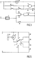
- FIG. 3 shows a schematic diagram of a more sophisticated heating apparatus, in this case a fan heater, in accordance with the invention.
- a live terminal L of the mains supply is connected to a first terminal of a neon indicator 52, to a first terminal of a switch 40 and to a first terminal of a thermostat T.
- a second terminal of the switch 40 is connected to a first terminal of a motor 14 which drives a fan (not shown) arranged to blow air over electrical heating elements 54 and 56.
- a second terminal of the thermostat T is connected to a first terminal of a switch 42 and to the first terminal of a switch 44.
- a second terminal of the switch 42 is connected to the first terminal of the motor 14 and to a first terminal of a 1 kilowatt heating element 54.
- a second terminal of the neon indicator 52 is connected to a second terminal of the motor 14, to the second terminal of a switch 50, to the second terminal of a 2 kilowatt heating element 56 (shown here as a pair of 1kW heating elements) and to a second terminal of a switch 48.
- a second terminal of the element 54 is connected to a first terminal of the switch 50.
- a first terminal of the element 56 is connected to a second terminal of the switch 44 and to a second terminal of a switch 46.
- a first terminal of the switch 46 is connected to a first terminal of the switch 48 and to the neutral terminal N of the mains supply via a thermal cutout C.
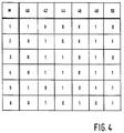
- the heating apparatus of Figure 3 has six modes of operation which are dependent upon the positions of the switches 40-50 in accordance with the table of Figure 4.
- the six modes are listed in a vertical column M and each mode has a row defining whether the six switches 40-50 are open (0), closed (1) or don't care (X).
- Mode 1 provides a cold blowing operation in which the fan motor 14 is activated but neither of the heating elements 54, 56 are activated.
- Mode 2 provides thermostatically controlled operation of the fan motor 14 and the 1kW element 54 but not the 2kW element 56.
- Mode 3 provides thermostatically controlled operation of the fan motor 14 and the 2 kilowatt element 56 but not the 1 kW element 54.
- Mode 4 provides thermostatically controlled operation of both the heating elements 54 and 56 to provide a total heat output of 3 kilowatt.
- Mode 5 provides 'comfort' operation in which the fan motor 14 and the 1 kilowatt element 54 are continually connected to the mains supply and the 2 kilowatt element 56 is thermostatically controlled by the thermostat T. This mode provides a substantially constant fan speed but alters the heat output of the fan heater in accordance with requirements.
- Mode 6 of the fan heater provides 'quiet' operation in which the fan motor 14 is connected in parallel with the 1kW element 54 and in series with the 2 kilowatt element 56. This connects the fan motor across approximately two thirds of the supply voltage giving a reduced fan speed and a heat output of approximately 700W for a 240V mains supply.
- switches 40 to 50 would conveniently be realised as a set of contacts on a single switch, for example a rotary switch, so that an operator of the heater can easily select the desired mode of operation.
- switch 44 opens before switch 46 closes and vice versa to avoid short-circuiting the mains supply.
- the thermostat could be arranged to switch between the quiet mode and one of the higher output modes 2, 3 or 4. This provides the heating required with less disturbance to users than fan heaters whose thermostat switches the whole heater on or off. Not only is the disturbance due to the magnitude of the difference between the two states reduced, but since the lower output does still provide some heat, the disturbance due to the frequency of the switching between states should also be reduced.
- FIG. 5 shows a schematic diagram of another embodiment of the present invention which provides a variety of fan speeds by using a plurality of heating elements wired in series, the fan motor being connected to a supply terminal and any one of a number of taps between the elements.
- a live terminal of the mains supply is connected to a first terminal of a motor 14, to a first contact 1 of a rotary switch 7 and to a first terminal of a heating element 60.
- a second terminal of the element 60 is connected to a contact 2 of the switch 7 and to a first terminal of a heating element 62.
- a second terminal of the heating element 62 is connected to a contact 3 of the switch 7 and to a first terminal of a heating element 64.
- a second terminal of the heating element 64 is connected to a contact 4 of the switch 7 and to a first terminal of a heating element 66.
- a second terminal of the heating element 66 is connected to a contact 5 of the switch 7 and to the neutral terminal of the mains supply.
- a second terminal of the motor 14 is connected to a wiper contact 6 of the switch 7 which wiper contact can be connected to any one of the contacts 1 to 5 by operation of the switch.
- the motor 14 is connected to drive a fan 15 arranged to blow air over the elements 60 to 66.
- the motor 14 When the switch 7 is in position 1 (wiper contact connected to contact 1) the motor 14 is effectively switched off and the heating apparatus functions as a pure convector heater.
- the physical construction of the apparatus must be such that it will not overheat in this mode as is well known to those skilled in the art.
- the motor 14 With the switch 7 at position 2 the motor 14 is in parallel with the element 60 and in series with the elements 62, 64 and 66. This provides the slowest fan speed.
- the switch 7 When the switch 7 is at position 3 the motor 14 is in parallel with the series combination of elements 60, 62 and in series with the elements 64 and 66 which provides a higher fan speed.
- the switch 7 at position 4 the motor 14 is in parallel with the series combination of elements 60, 62, 64 and in parallel with the element 66 which provides a still higher fan speed.
- the heating apparatus in Figure 5 thus provides a convector heater with fan assistance.
- the different positions of the switch 7 barely alter the heat output of the apparatus; they only alter the speed at which the heat is distributed to the surrounding air. Where a convector heater is not required, position 1 of the switch 7 may be omitted.
- the heating elements 60 to 66 may actually be provided by a number of taps on a singly wound heating element. The resistances of the elements 60 to 66 need not be the same but may be chosen to provide a convenient range of fan speeds.
- the arrangement of Figure 5 may be incorporated with other series/parallel element arrangements and thermostatic switches to provide a variety of heater characteristics as required.
- the present invention is particularly applicable to the manufacture of fan heaters for use in domestic, automotive or industrial environments.
Landscapes
- Engineering & Computer Science (AREA)
- Physics & Mathematics (AREA)
- Thermal Sciences (AREA)
- Chemical & Material Sciences (AREA)
- Combustion & Propulsion (AREA)
- Mechanical Engineering (AREA)
- General Engineering & Computer Science (AREA)
- Direct Air Heating By Heater Or Combustion Gas (AREA)
- Control Of Resistance Heating (AREA)
Claims (9)
- Heizgerät, welches mehrere elektrische Heizelemente (54, 56), ein von einem elektrischen Motor (14) angetriebenes Gebläse, welches so angeordnet ist, dass es Luft über die elektrischen Heizelemente bläst, sowie Schaltmittel (7, 40, 42, 44, 46, 48, 50) aufweist, dadurch gekennzeichnet, dass die Anordnung vorsieht:einen ersten Heizmodus, in welchem ein erstes Heizelement (54, 60) parallel zu dem Motor (14) und ein zweites Heizelement (56, 62) in Reihe mit dem Motor geschaltet ist, wobei die Heizelemente hintereinander geschaltet sind, sowieeinen zweiten Heizmodus, in welchem das erste und zweite Heizelement (54, 56, 60, 62) parallel zu dem Motor (14) geschaltet sind.
- Heizgerät nach Anspruch 1, dadurch gekennzeichnet, dass das erste und zweite Heizelement (54, 56) parallel zueinander geschaltet sind.
- Heizgerät nach Anspruch 2, dadurch gekennzeichnet, dass die Schaltmittel (7, 40, 42, 44, 46, 48, 50) ferner dazu angeordnet sind, einen dritten Heizmodus vorzusehen, bei welchem eines der Heizelemente (54) zu dem Motor parallel geschaltet und das andere Element (56) getrennt ist.
- Heizgerät nach Anspruch 2, dadurch gekennzeichnet, dass außerdem Thermostatmittel (T) vorgesehen sind, und dass die Schaltmittel (40, 42, 44, 46, 48, 50) so angeordnet sind, dass eines der Elemente (54) in dem zweiten Heizmodus durch die Thermostatmittel (T) geregelt wird.
- Heizgerät nach Anspruch 4, dadurch gekennzeichnet, dass die Schaltmittel eine Anordnung aus sechs einpoligen Schaltern (40, 42, 44, 46, 48, 50) aufweisen und die Heizelemente (54, 56) unterschiedliche Wärmewerte vorsehen.
- Heizgerät nach Anspruch 1, dadurch gekennzeichnet, dass das erste und zweite Heizelement (60, 62) in dem zweiten Heizmodus in Reihe und parallel zu dem Motor (14) angeordnet sind.
- Heizgerät nach Anspruch 6, dadurch gekennzeichnet, dass mehrere weitere Heizelemente (64, 66) in Reihe mit dem ersten und zweiten Heizelement (60, 62) vorgesehen sind, wobei die Schaltmittel (7) so angeordnet sind, dass weitere Heizmoden, bei welchen die weiteren Heizelemente konsekutiv parallel zu dem Motor (14) geschaltet werden können, vorgesehen werden können.
- Heizgerät nach Anspruch 7, dadurch gekennzeichnet, dass die Schaltmittel (7) so angeordnet sind, dass ein zusätzlicher Modus, bei welchem der Motor (14) abgeschaltet ist, vorgesehen werden kann.
- Heizgerät nach Anspruch 8, dadurch gekennzeichnet, dass die Schaltmittel (7) durch einen Drehschalter mit fünf Einstellungen dargestellt sind, wobei die Schaltkontakte (1, 2, 3, 4, 5) an die äußeren Enden und die Verbindungen zwischen einer Anordnung aus vier hintereinandergeschalteten Heizelementen (60, 62, 64, 66) angeschlossen sind.
Applications Claiming Priority (3)
| Application Number | Priority Date | Filing Date | Title |
|---|---|---|---|
| GB9326586A GB9326586D0 (en) | 1993-12-31 | 1993-12-31 | Electrical heating apparatus |
| GB9326586 | 1993-12-31 | ||
| PCT/IB1994/000441 WO1995018516A1 (en) | 1993-12-31 | 1994-12-23 | Electrical heating apparatus |
Publications (2)
| Publication Number | Publication Date |
|---|---|
| EP0687404A1 EP0687404A1 (de) | 1995-12-20 |
| EP0687404B1 true EP0687404B1 (de) | 2000-03-29 |
Family
ID=10747317
Family Applications (1)
| Application Number | Title | Priority Date | Filing Date |
|---|---|---|---|
| EP95902912A Expired - Lifetime EP0687404B1 (de) | 1993-12-31 | 1994-12-23 | Elektrisches heizgerät |
Country Status (6)
| Country | Link |
|---|---|
| US (1) | US5825974A (de) |
| EP (1) | EP0687404B1 (de) |
| DE (1) | DE69423747T2 (de) |
| GB (1) | GB9326586D0 (de) |
| SG (1) | SG52748A1 (de) |
| WO (1) | WO1995018516A1 (de) |
Families Citing this family (34)
| Publication number | Priority date | Publication date | Assignee | Title |
|---|---|---|---|---|
| TW377837U (en) * | 1999-04-22 | 1999-12-21 | chuan-xing Zheng | Temperature-return prevented apparatus for hot air gun |
| TW475890B (en) * | 1999-07-16 | 2002-02-11 | Tek Maker Corp | Portable hot-air blower |
| US6408131B2 (en) * | 2000-07-12 | 2002-06-18 | Tek Maker Corporation | Portable dryer with different circuit designs |
| US20020152281A1 (en) * | 2001-04-13 | 2002-10-17 | Ko-Chien Chuang | Online device and method for downloading and sharing information by one touch |
| DE10140094B4 (de) * | 2001-08-16 | 2006-03-30 | Robert Bosch Gmbh | Kühlgebläse, insbesondere für Kraftfahrzeuge |
| US6624397B2 (en) * | 2001-10-01 | 2003-09-23 | Art K. Tateishi | Electric circuit for portable heater |
| KR100423877B1 (ko) * | 2002-02-01 | 2004-03-22 | 이걸주 | 진공포장기 |
| US7153286B2 (en) | 2002-05-24 | 2006-12-26 | Baxter International Inc. | Automated dialysis system |
| DE10260019B4 (de) * | 2002-12-19 | 2005-11-24 | Miele & Cie. Kg | Haushalts-Speisenwärmer zum Warmhalten von Speisen und Getränken |
| US7204067B2 (en) | 2003-02-27 | 2007-04-17 | Sunbeam Products, Inc. | Vacuum packaging appliance with removable trough |
| US7207160B2 (en) * | 2003-02-27 | 2007-04-24 | Sunbeam Products, Inc. | Vacuum packaging appliance with vacuum side channel latches |
| US20040200089A1 (en) * | 2003-04-09 | 2004-10-14 | Gerardo Melendrez | Body dryer |
| US6933470B2 (en) * | 2003-07-24 | 2005-08-23 | Tilia International, Inc. | Incremental seal wire activation |
| US20050022480A1 (en) * | 2003-07-29 | 2005-02-03 | David Brakes | Vacuum packaging appliances including support assemblies for carrying bag material |
| US7021027B2 (en) * | 2003-07-29 | 2006-04-04 | Tilia International, Inc. | Vacuum pump control and vacuum feedback |
| US20050039420A1 (en) * | 2003-07-31 | 2005-02-24 | Albritton Charles Wade | Fluid sensing in a drip tray |
| US7478516B2 (en) | 2003-07-31 | 2009-01-20 | Sunbeam Products, Inc. | Vacuum packaging appliance |
| US7197861B2 (en) * | 2003-07-31 | 2007-04-03 | Sunbeam Products, Inc. | Vacuum packaging appliances |
| TWI279359B (en) | 2003-07-31 | 2007-04-21 | Tilia Int Inc | Lidless vacuum appliance |
| US7021034B2 (en) * | 2003-07-31 | 2006-04-04 | Tilia International, Inc. | Decoupled vacuum packaging appliance |
| US20050022474A1 (en) * | 2003-07-31 | 2005-02-03 | Albritton Charles Wade | Heat sealing element and control of same |
| US6873792B2 (en) * | 2003-08-26 | 2005-03-29 | Tek Maker Corporation | Multiple-setting portable dryer and circuit designs thereof |
| US6901214B2 (en) * | 2003-08-26 | 2005-05-31 | Tek Maker Corporation | Multiple-setting portable dryer and circuit designs thereof |
| US20050083638A1 (en) * | 2003-10-20 | 2005-04-21 | International Resistive Company | Resistive film on aluminum tube |
| WO2005124244A1 (en) * | 2004-06-16 | 2005-12-29 | Woo Young Park | Hot-air blower having artificial intelligence |
| CN100377676C (zh) * | 2004-10-13 | 2008-04-02 | 桓科股份有限公司 | 可携式吹风机 |
| WO2006091477A2 (en) * | 2005-02-21 | 2006-08-31 | International Resistive Company, Inc. | System, method and tube assembly for heating automotive fluids |
| US20060213148A1 (en) * | 2005-03-24 | 2006-09-28 | Baptista Alexandre A | Portable vacuum packaging appliance |
| US20060263073A1 (en) * | 2005-05-23 | 2006-11-23 | Jcs/Thg,Llp. | Multi-power multi-stage electric heater |
| US8027572B2 (en) | 2008-02-22 | 2011-09-27 | Baxter International Inc. | Dialysis machine having multiple line voltage heater |
| US9435459B2 (en) * | 2009-06-05 | 2016-09-06 | Baxter International Inc. | Solenoid pinch valve apparatus and method for medical fluid applications having reduced noise production |
| TWI568307B (zh) * | 2011-11-02 | 2017-01-21 | Meng-Hua Yu | Fixed power electric heating device |
| AU2014277832B2 (en) * | 2013-12-23 | 2019-10-31 | Legrand Australia Pty Ltd | Fan heater |
| DE102019006554A1 (de) * | 2019-09-18 | 2021-03-18 | Truma Gerätetechnik GmbH & Co. KG | Heizvorrichtung |
Family Cites Families (11)
| Publication number | Priority date | Publication date | Assignee | Title |
|---|---|---|---|---|
| FR649754A (de) * | ||||
| US1574343A (en) * | 1921-10-14 | 1926-02-23 | Ernest O Frederics | Hair-drying machine |
| US1607195A (en) * | 1924-11-13 | 1926-11-16 | Eastern Lab Inc | Electric hair drier |
| CH162330A (de) * | 1932-04-05 | 1933-06-15 | Bbc Brown Boveri & Cie | Einrichtung zur elektrischen Heizung von Eisenbahnwagen. |
| US2552470A (en) * | 1946-09-06 | 1951-05-08 | Electrolux Corp | Air circulator and heater |
| US2647198A (en) * | 1951-03-10 | 1953-07-28 | Knapp Monarch Co | Control circuit for air fan heaters |
| DE1122644B (de) * | 1958-06-02 | 1962-01-25 | Licentia Gmbh | Schaltanordnung fuer Raumheizgeraete |
| NL6804403A (de) * | 1968-03-28 | 1969-09-30 | ||
| US4110600A (en) * | 1976-06-24 | 1978-08-29 | Mcgraw-Edison Company | Thermostatically controlled plural heat output portable electric space heater |
| FR2456489A1 (fr) * | 1979-05-18 | 1980-12-12 | Velecta Sa | Dispositif de controle de la puissance de chauffage d'une resistance electrique et de la vitesse d'un moteur electrique de ventilateur notamment dans un seche-cheveux |
| FR2608259B1 (fr) * | 1986-12-10 | 1989-03-31 | Seb Sa | Convecteur electrique de chauffage a double regime |
-
1993
- 1993-12-31 GB GB9326586A patent/GB9326586D0/en active Pending
-
1994
- 1994-12-23 DE DE69423747T patent/DE69423747T2/de not_active Expired - Fee Related
- 1994-12-23 EP EP95902912A patent/EP0687404B1/de not_active Expired - Lifetime
- 1994-12-23 WO PCT/IB1994/000441 patent/WO1995018516A1/en not_active Ceased
- 1994-12-23 SG SG1996008806A patent/SG52748A1/en unknown
- 1994-12-28 US US08/366,148 patent/US5825974A/en not_active Expired - Fee Related
Also Published As
| Publication number | Publication date |
|---|---|
| EP0687404A1 (de) | 1995-12-20 |
| DE69423747D1 (de) | 2000-05-04 |
| GB9326586D0 (en) | 1994-03-02 |
| DE69423747T2 (de) | 2000-10-19 |
| US5825974A (en) | 1998-10-20 |
| SG52748A1 (en) | 1998-09-28 |
| WO1995018516A1 (en) | 1995-07-06 |
Similar Documents
| Publication | Publication Date | Title |
|---|---|---|
| EP0687404B1 (de) | Elektrisches heizgerät | |
| US4110600A (en) | Thermostatically controlled plural heat output portable electric space heater | |
| US4347432A (en) | Glass ceramic cooking appliance | |
| US4327278A (en) | Simplified multiple speed hair dryer | |
| JP2000225834A (ja) | 自動車用電気加熱装置 | |
| US4723593A (en) | Room temperature control unit responsive to occupancy | |
| US5615829A (en) | Air conditioning system thermostat having adjustable cycling rate | |
| JP2786883B2 (ja) | ヘアードライヤー | |
| JPH08508088A (ja) | 電気暖房装置 | |
| US3388236A (en) | Control for a surface heater for cooking apparatus | |
| GB2293098A (en) | Hair drier | |
| JPH06100377B2 (ja) | 風温制御装置 | |
| JPH05272810A (ja) | 電気温風機の送風モータ制御回路 | |
| US4423335A (en) | Energy controller and method utilizing bi-metal elements to adjust thermostat setting and to shed and restore controlled loads in prioritized order | |
| JPH07110163A (ja) | 電気温風機 | |
| JPS6456995A (en) | Speed adjusting device for electric fan | |
| JPH029268B2 (de) | ||
| JPH0137522Y2 (de) | ||
| JPS586222Y2 (ja) | 温風暖房機の制御回路 | |
| JPH03168523A (ja) | 加熱調理器 | |
| JP2608874B2 (ja) | 電気床暖房器具 | |
| JPS5951817A (ja) | 電気ジャー炊飯器 | |
| JPH1064664A (ja) | Ptcコントローラ | |
| JPS6324490Y2 (de) | ||
| JPS5827708Y2 (ja) | 電熱装置 |
Legal Events
| Date | Code | Title | Description |
|---|---|---|---|
| PUAI | Public reference made under article 153(3) epc to a published international application that has entered the european phase |
Free format text: ORIGINAL CODE: 0009012 |
|
| AK | Designated contracting states |
Kind code of ref document: A1 Designated state(s): DE FR GB |
|
| 17P | Request for examination filed |
Effective date: 19960108 |
|
| 17Q | First examination report despatched |
Effective date: 19981005 |
|
| GRAG | Despatch of communication of intention to grant |
Free format text: ORIGINAL CODE: EPIDOS AGRA |
|
| GRAG | Despatch of communication of intention to grant |
Free format text: ORIGINAL CODE: EPIDOS AGRA |
|
| GRAH | Despatch of communication of intention to grant a patent |
Free format text: ORIGINAL CODE: EPIDOS IGRA |
|
| GRAH | Despatch of communication of intention to grant a patent |
Free format text: ORIGINAL CODE: EPIDOS IGRA |
|
| GRAA | (expected) grant |
Free format text: ORIGINAL CODE: 0009210 |
|
| AK | Designated contracting states |
Kind code of ref document: B1 Designated state(s): DE FR GB |
|
| REF | Corresponds to: |
Ref document number: 69423747 Country of ref document: DE Date of ref document: 20000504 |
|
| ET | Fr: translation filed | ||
| PGFP | Annual fee paid to national office [announced via postgrant information from national office to epo] |
Ref country code: FR Payment date: 20001226 Year of fee payment: 7 |
|
| PLBE | No opposition filed within time limit |
Free format text: ORIGINAL CODE: 0009261 |
|
| STAA | Information on the status of an ep patent application or granted ep patent |
Free format text: STATUS: NO OPPOSITION FILED WITHIN TIME LIMIT |
|
| 26N | No opposition filed | ||
| REG | Reference to a national code |
Ref country code: GB Ref legal event code: IF02 |
|
| PG25 | Lapsed in a contracting state [announced via postgrant information from national office to epo] |
Ref country code: FR Free format text: LAPSE BECAUSE OF NON-PAYMENT OF DUE FEES Effective date: 20020830 |
|
| REG | Reference to a national code |
Ref country code: FR Ref legal event code: ST |
|
| PGFP | Annual fee paid to national office [announced via postgrant information from national office to epo] |
Ref country code: GB Payment date: 20031224 Year of fee payment: 10 |
|
| PGFP | Annual fee paid to national office [announced via postgrant information from national office to epo] |
Ref country code: DE Payment date: 20040216 Year of fee payment: 10 |
|
| PG25 | Lapsed in a contracting state [announced via postgrant information from national office to epo] |
Ref country code: GB Free format text: LAPSE BECAUSE OF NON-PAYMENT OF DUE FEES Effective date: 20041223 |
|
| PG25 | Lapsed in a contracting state [announced via postgrant information from national office to epo] |
Ref country code: DE Free format text: LAPSE BECAUSE OF NON-PAYMENT OF DUE FEES Effective date: 20050701 |
|
| GBPC | Gb: european patent ceased through non-payment of renewal fee |
Effective date: 20041223 |