EP0688948B1 - Vorrichtung zum Zuführen von Startbrennstoff zu einem Vergaser - Google Patents
Vorrichtung zum Zuführen von Startbrennstoff zu einem Vergaser Download PDFInfo
- Publication number
- EP0688948B1 EP0688948B1 EP95109219A EP95109219A EP0688948B1 EP 0688948 B1 EP0688948 B1 EP 0688948B1 EP 95109219 A EP95109219 A EP 95109219A EP 95109219 A EP95109219 A EP 95109219A EP 0688948 B1 EP0688948 B1 EP 0688948B1
- Authority
- EP
- European Patent Office
- Prior art keywords
- shaft
- fuel
- passage
- carburetor
- valve
- Prior art date
- Legal status (The legal status is an assumption and is not a legal conclusion. Google has not performed a legal analysis and makes no representation as to the accuracy of the status listed.)
- Expired - Lifetime
Links
- 239000000446 fuel Substances 0.000 title claims description 91
- 239000000203 mixture Substances 0.000 claims description 13
- 230000001105 regulatory effect Effects 0.000 claims description 8
- 238000011144 upstream manufacturing Methods 0.000 claims description 4
- 230000002093 peripheral effect Effects 0.000 claims description 3
- 239000002828 fuel tank Substances 0.000 description 6
- 230000001133 acceleration Effects 0.000 description 4
- 239000002131 composite material Substances 0.000 description 3
- 238000010276 construction Methods 0.000 description 2
- 230000000881 depressing effect Effects 0.000 description 2
- 239000007789 gas Substances 0.000 description 2
- 238000010792 warming Methods 0.000 description 2
- 235000001674 Agaricus brunnescens Nutrition 0.000 description 1
- 238000002485 combustion reaction Methods 0.000 description 1
- 230000007423 decrease Effects 0.000 description 1
- 230000000994 depressogenic effect Effects 0.000 description 1
- 238000004519 manufacturing process Methods 0.000 description 1
- 239000007858 starting material Substances 0.000 description 1
Images


Classifications
-
- F—MECHANICAL ENGINEERING; LIGHTING; HEATING; WEAPONS; BLASTING
- F02—COMBUSTION ENGINES; HOT-GAS OR COMBUSTION-PRODUCT ENGINE PLANTS
- F02M—SUPPLYING COMBUSTION ENGINES IN GENERAL WITH COMBUSTIBLE MIXTURES OR CONSTITUENTS THEREOF
- F02M1/00—Carburettors with means for facilitating engine's starting or its idling below operational temperatures
- F02M1/04—Carburettors with means for facilitating engine's starting or its idling below operational temperatures the means to facilitate starting or idling being auxiliary carburetting apparatus able to be put into, and out of, operation, e.g. having automatically-operated disc valves
- F02M1/046—Auxiliary carburetting apparatus controlled by piston valves
-
- F—MECHANICAL ENGINEERING; LIGHTING; HEATING; WEAPONS; BLASTING
- F02—COMBUSTION ENGINES; HOT-GAS OR COMBUSTION-PRODUCT ENGINE PLANTS
- F02M—SUPPLYING COMBUSTION ENGINES IN GENERAL WITH COMBUSTIBLE MIXTURES OR CONSTITUENTS THEREOF
- F02M17/00—Carburettors having pertinent characteristics not provided for in, or of interest apart from, the apparatus of preceding main groups F02M1/00 - F02M15/00
- F02M17/02—Floatless carburettors
- F02M17/04—Floatless carburettors having fuel inlet valve controlled by diaphragm
-
- F—MECHANICAL ENGINEERING; LIGHTING; HEATING; WEAPONS; BLASTING
- F02—COMBUSTION ENGINES; HOT-GAS OR COMBUSTION-PRODUCT ENGINE PLANTS
- F02M—SUPPLYING COMBUSTION ENGINES IN GENERAL WITH COMBUSTIBLE MIXTURES OR CONSTITUENTS THEREOF
- F02M19/00—Details, component parts, or accessories of carburettors, not provided for in, or of interest apart from, the apparatus of groups F02M1/00 - F02M17/00
- F02M19/12—External control gear, e.g. having dash-pots
- F02M19/126—Connecting rods between at least a throttle valve and an accelerating pump
-
- F—MECHANICAL ENGINEERING; LIGHTING; HEATING; WEAPONS; BLASTING
- F02—COMBUSTION ENGINES; HOT-GAS OR COMBUSTION-PRODUCT ENGINE PLANTS
- F02M—SUPPLYING COMBUSTION ENGINES IN GENERAL WITH COMBUSTIBLE MIXTURES OR CONSTITUENTS THEREOF
- F02M7/00—Carburettors with means for influencing, e.g. enriching or keeping constant, fuel/air ratio of charge under varying conditions
- F02M7/06—Means for enriching charge on sudden air throttle opening, i.e. at acceleration, e.g. storage means in passage way system
- F02M7/08—Means for enriching charge on sudden air throttle opening, i.e. at acceleration, e.g. storage means in passage way system using pumps
-
- Y—GENERAL TAGGING OF NEW TECHNOLOGICAL DEVELOPMENTS; GENERAL TAGGING OF CROSS-SECTIONAL TECHNOLOGIES SPANNING OVER SEVERAL SECTIONS OF THE IPC; TECHNICAL SUBJECTS COVERED BY FORMER USPC CROSS-REFERENCE ART COLLECTIONS [XRACs] AND DIGESTS
- Y10—TECHNICAL SUBJECTS COVERED BY FORMER USPC
- Y10S—TECHNICAL SUBJECTS COVERED BY FORMER USPC CROSS-REFERENCE ART COLLECTIONS [XRACs] AND DIGESTS
- Y10S261/00—Gas and liquid contact apparatus
- Y10S261/08—Carburetor primers
Definitions
- the present invention relates to an apparatus for supplying starting-fuel in a diaphragm type carburetor for an internal combustion engine (hereinafter merely referred to as the engine) such as an engine for portable operating machines such as a power saw, a reaper and the like, particularly for a carburetor provided with a bistarter mechanism by which the engine is easily started.
- a diaphragm type carburetor for an internal combustion engine hereinafter merely referred to as the engine
- the engine such as an engine for portable operating machines such as a power saw, a reaper and the like
- the operation of the bistarter and the operation of starting the engine have to be performed independently and simultaneously, and therefore their operation is cumbersome.
- the starting fuel supplying apparatus is so large in size that the apparatus is difficult to be employed for a portable operating machine which has a limited space for the engine to be mounted.
- a carburetor with an automatically operable bistarter supplying an enriched fuel and air mixture when an engine is cranked for starting and for initial running of the engine upon starting.
- the enriching fuel and air are mixed in a chamber and supplied through a control valve to the main carburetor suction or venturi passage downstream of a throttle valve.
- the control valve is opened and energized for operation by movement of a manual starting button which rotates a starting shaft against the bias of a spring to move a valve plunger which is engaged by a cam on the starting shaft to its open position.
- a retaining arm moves into engagement with a starting plate carried by the starting shaft to lock the starting shaft in the operating or open position of the control valve.
- the retaining arm is rotated by a cam on the throttle valve shaft to release the locking of the starting plate which permits the starting shaft to rotate which causes the cam to move the plunger to the closed position of the control valve to stop the flow of the enriching fuel and air mixture into the carburetor intake passage.
- closing of the control valve to shut off the enriching fuel and air mixture can also be initiated by manually moving the starting button.
- This bistarter eliminates the conventional choke valve and system which substantially improves low engine speed operation stability, increases the maximum output of the engine, provides a richer fuel and air starting mixture than a conventional choke valve system and improves the engine starting and warm up properties.
- Objects, features and advantages of this invention are to provide a carburetor with a bistarter which is automatically operable, simple in starting operation, extremely compact, improves the safety of portable operating machinery by limiting the speed at which the engine rotates when starting to less than the speed at which a clutch of the machinery automatically engages, supplies to the engine a richer fuel and air mixture than that normally supplied by a conventional choke system, enhances the starting and warm up of an engine, improves the stability of the speed of engine operation, increases the output of the engine, enhances the ability to control exhaust gases, can be utilized with carburetor bodies which were constructed for use of a conventional choke valve and shaft, and is rugged, durable, of relatively simple design, economical manufacture and assembly, and a long useful life in service.
- a carburetor with a starting-fuel supplying apparatus has a carburetor body 15 mounted, along with an air cleaner not shown, on an intake port of an engine by means of bolts which extend through a pair of left and right bolt holes 15a.
- a cover 9 is connected to an upper end wall of the body 15 through a film or diaphragm 10.
- a chamber for introducing a pulsating pressure of a crankcase chamber of a 2-stroke engine and a pump chamber are defined on the upper and lower sides, respectively, of the diaphragm 10 to constitute a fuel pump D.
- the fuel pump D sucks fuel from a fuel tank 46 through a pipe 58 and an inlet 58a to supply the fuel to a constant pressure fuel metering chamber 47 of a constant pressure fuel supply mechanism C through a flow valve not shown.
- a cover 51 is connected to a lower end wall of the body 15 through a film or diaphragm 49, and a constant pressure fuel chamber 47 and an atmospheric chamber 51 are defined on the upper and lower sides, respectively, of the diaphragm 49.
- a lever 50 is pivotally supported on the wall of the constant pressure fuel chamber 47 by means of a support shaft 57 with the lever 50 having one end engaged with the diaphragm 49 and the other end engaged with a fuel flow control valve (not shown).
- the fuel in the constant pressure fuel chamber 47 is sucked from a high speed fuel jet 17 into an intake passage 31 extending through the body 15 through a passage 48, a high speed fuel regulating needle valve 53 and a check valve 55.
- fuel is likewise sucked from a plurality of low speed fuel jets 17a into the intake passage 31.
- a well known throttle valve 32 is disposed in the intake passage 31 on a throttle valve shaft 14.
- the low speed fuel jets 17a are axially juxtaposed in the vicinity of a closed position (accurately, an idle position) of the throttle valve 32 of the intake passage 31.
- the high speed fuel jet 17 is disposed in a venturi portion 16 upstream of the throttle valve 32 of the intake passage 31.
- a hand-operated suction pump 41 connected between the constant pressure fuel chamber 47 and the fuel tank 46 to supply fuel from the fuel tank 46 through the fuel pump D to the constant pressure fuel chamber 47.
- a flexible bulb or dome 44a is connected to a body 44, and a mushroom composite check valve 43 (an integral combination of an intake valve and a discharge valve) is disposed within the dome 44a.
- a piston type acceleration pump B is disposed within the body 15.
- the acceleration pump B has a piston 2 fitted in a cylinder 3 extending transversely across a bore in which the throttle valve shaft 14 is received.
- the cylinder 3 has its outer end portion closed by a plug 34 having an annular groove 34a.
- the piston 2 is urged into engagement with a notched cam 14a in the through shaft by a spring 4 interposed between the inner end of the cylinder 3 and the piston 2.
- a valve lever 12 is connected to the left end of the throttle valve shaft 14, and the throttle valve 32 is biased to be rotated to its closed position by a spring 13 fastened between the valve lever 12 and the body 15.
- a stop ring 36 is received on the right end of the throttle valve shaft 14 and axial movement of the throttle valve shaft 14 is prevented by the ring and spring 13.
- a cam 37 is connected to the right end of the throttle valve shaft 14.
- the throttle valve shaft 14 is formed with a notched cam 14a and an annular groove 14b within the body 15.
- the bistarter A has a starting-fuel regulating needle valve 29, a starting actuator shaft 21 supported in parallel with the throttle valve shaft 14 within the body 15, and a plunger 6 disposed between the throttle valve shaft 14 and the starting shaft 21.
- a retainer 23 is received in an annular groove of the starting actuator shaft 21 and secured to the right end wall of the body 15 by a screw so that the starting shaft 21 will not move axially.
- the body 15 is interiorly formed with a cylinder 22 perpendicular to the starting shaft 21, and a plunger 6 fitted in the cylinder is urged into engagement with a notched cam 21a of the starting shaft 21 by the force produced by a spring 63 (Fig. 3).
- the spring 63 is interposed between the plunger 6 and a spring seat 62, and the spring seat 62 holds an O-ring 61 at the end of the cylinder 22.
- the plunger 6 is integrally provided with a valve body 6a, and the valve body comes into engagement with the O-ring 61 at an advanced position of the plunger 6 as shown in Fig. 3 to provide a cutoff valve between the passage 8 and the passage 7.
- the cylinder 22 communicates with a valve chamber 65 of the starting-fuel regulating needle valve 29 through the passage 8.
- the valve chamber 65 is opened to a portion of the intake passage 31 upstream of the throttle valve 32 through the internal passage 20 of the starting shaft 21 and the passage 18 in the body 15. As shown in Fig.
- one end of the passage 20 opens to the peripheral surface of the starting shaft 21 and provides a valve which is opened and closed by rotation of the starting shaft 21.
- the other end of the passage 20 is opened to the end of the starting shaft 21 and the passage 18.
- the valve chamber 65 of the starting-fuel regulating needle valve 29 crosses between the passage 8 and the passage 20. As shown in Fig. 1, the end on the inlet side of the chamber 65 communicates with the constant pressure fuel chamber 47 through the passage 19 and a check valve 28.
- the cylinder 22 communicates with the carburetor intake passage 31 (downstream of the throttle valve 32) through the passage 7, annular groove 14b, passage 35, annular groove 34a and passage 33.
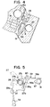
- the operating mechanism of the bistarter A has a transverse lever or pin 26 which extends through and is supported on the starting shaft 21, a starting plate 27 rotatably supported on the starting shaft 21, a bell crank 39 rotatably supported by a shaft 40 on the body 15, and a cam 37 connected to the throttle valve shaft 14 for rotation therewith.
- a torsion spring 25 received on the starting shaft 21 has one end fastened to the body 15 and the other end fastened to the pin 26 to rotate and bias the starting shaft 21 (clockwise in Fig. 5) toward the extended or closed position of the plunger 6 shown in Fig. 3.
- a torsion spring 38 received on the support shaft 40 has one end fastened to the body 15 and the other end fastened to the bell crank 39 to rotate and bias the bell crank 39 clockwise as viewed in Fig. 5.
- the starting plate 27 is connected to a starting button 59 by a shaft or wire 59a and has a bent tab 27a in contact with one end of the pin 26, a stop lever 27b in contact with the end of a retaining arm 39a of the bell crank 39, and a cam 27c engagable with the retaining arm 39a.
- the bell crank 39 has the retaining arm 39a, a protrusion 39b engagable with the pin 26, and an arm 39c in to contact with the cam 37. When the protrusion 39b comes in contact with the pin 26, clockwise rotation of the starting plate 27 about the starting shaft 21 is prohibited.
- the suction pump 41 Prior to starting the engine, the suction pump 41 is operated to remove fuel vapor and air from the constant pressure fuel chamber 47 and supply fuel from the fuel tank 46 to the constant pressure fuel chamber 47. Subsequently, when the starting button 59 is pulled to rotate the starting plate 27 from the position indicated by the chain line in Fig. 5 counterclockwise about the starting shaft 21, the bent tab 27a bears on the lever pin 26 so that the starting shaft 21 is rotated counterclockwise against the force of the spring 25.
- the supply of the starting mixture may be discontinued by manually depressing the starting button 59.
- the starting button 59 When the starting button 59 is depressed, only the starting plate 27 rotates clockwise about the starting shaft 21.
- the retaining arm 39a is moved rightward (counterclockwise in Fig. 5) by the cam 27c of the starting plate 27. This releases the locking or latch between the protrusion 39b of the retaining arm 39a and the pin 26 of the starting shaft 21, so that the starting shaft 21 is rotated clockwise by the force of the spring 25, and the pin 26 of the starting shaft 21 then bears upon the bent tab 27a which in turn bears upon the boss portion of the bell crank 39.
- the starting-fuel supplying apparatus Since the starting-fuel supplying apparatus is housed in the carburetor body, the carburetor is small in size, and foreign matter and moisture cannot possibly invade the starting-fuel supplying apparatus.
- acceleration pump and the bistarter are housed in the carburetor body, it is possible to fully cope with exhaust gas control.
- the bistarter can be operated merely by pulling and releasing the starting button. Further, the operation of the bistarter can be stopped after completion of engine warming up merely by either depressing the starting button or operating the throttle valve. Thus, operation is very simple.
- the starting shaft can be disposed to be operated at substantially the same location and at the same operating angle as that of a conventional choke valve shaft, it can be mounted on a carburetor body having the same specification and construction as that of a choke valve system without changing the construction of the carburetor body.
Landscapes
- Engineering & Computer Science (AREA)
- Chemical & Material Sciences (AREA)
- Combustion & Propulsion (AREA)
- Mechanical Engineering (AREA)
- General Engineering & Computer Science (AREA)
- Means For Warming Up And Starting Carburetors (AREA)
Claims (11)
- Vergaser mit einem Gehäuse (15), einem durch das Gehäuse verlaufenden Gemischkanal (31) mit einem Luft-Einlaß und einem Kraftstoff/Luftgemisch-Auslaß, einem Drosselventil (32), das in dem Gemischkanal zwischen dem Einlaß und dem Auslaß angeordnet und an einer von dem Gehäuse (15) getragenen Drosselwelle (14) angebracht ist, einer Kraftstoffkammer (47), die von dem Gehäuse (15) getragen wird, einer Hauptdosierdüse (17), die mit dem Gemischkanal (31) stromauf des Drosselventils (32) und mit der Kraftstoftkammer (47) in Strömungsverbindung steht, einer Gemischkammer (65), die von dem Gehäuse (15) getragen wird, einem Kraftstoffeinlaßkanal (19), der mit der Gemischkammer (65) und der Kraftstoffkammer (47) verbunden ist, einem Lufteinlaßkanal (18, 20), der mit der Gemischkammer (65) und dem Gemischkanal (31) stromauf des Drosselventils (32) verbunden ist, der Luft zur Mischung mit Kraftstoff in der Gemischkammer (65) zuführt, einem Auslaßkanal (8, 7, 35, 33), der mit Gemischkammer (65) und dem Gemischkanal (31) stromab des Drosselventils (32) verbunden ist, um ein Gemisch aus Kraftstoff und Luft von der Gemischkammer (65) zu dem Gemischkanal (31) stromab des Drosselventils (32) zu führen, einem von dem Gehäuse getragenen Steuerventil, das mit dem Auslaßkanal (7, 35, 33) verbunden ist und einen Kolben (6) hat, der in eine Schließstellung und eine Öffnungsstellung des Steuerventils bewegbar ist, um den Strom eines Luft/Kraftstoffgemisches aus der Gemischkammer (65) zu dem Gemischkanal (31) zu steuern, gekennzeichnet durch eine Betätigungswelle (21), die von dem Gehäuse (15) getragen wird und mit dem Kolben (6) verbunden ist, um den Kolben (6) in Abhängigkeit von Drehbewegungen der Betätigungswelle (21) in eine Öffnungs- und Schließstellung des Steuerventils zu bewegen, und einen Betätigungsmechanismus (27, 39, 37), der mit der Betätigungswelle (21) und der Drosselwelle (14) verbunden ist, um die Betätigungswelle (21) in der Öffnungsstellung des Steuerventils lösbar zu halten und um die Betätigungswelle (21) freizugeben und in die Schließstellung des Steuerventils in Abhängigkeit von Drehbewegungen der Drosselwelle (14) zu drehen, um dadurch das Drosselventil (32) aus einer Leerlaufstellung in eine voll geöffnete Stellung des Drosselventils (32) zu bewegen.
- Vergaser nach Anspruch 1, bei dem der Kolben (6) mit einem Nocken (21 a) an der Betätigungswelle (21) zusammenwirkt, um das Steuerventil in Abhängigkeit von einer Drehung der Betätigungswelle (21) zu öffnen und zu schließen.
- Vergaser nach Anspruch 1, der ferner eine Kolbenbeschleunigerpumpe (B) aufweist, die von dem Gehäuse (15) getragen wird und mit der Drosselwelle (14) verbunden ist.
- Vergaser nach Anspruch 1, der ferner ein verstellbares Nadelventil (29) aufweist, das dem Kraftstoffeinlaßkanal (19) zugeordnet ist, um die Menge des dem Gemischkanal (31) zugeführten Kraftstoffs zu regeln und zu verstellen.
- Vergaser nach Anspruch 1, bei dem eine Ringnut (14b) in dem Außenumfang der Drosselwelle (14) gebildet ist und die Ringnut in dem Auslaßkanal (7, 35, 33) angeordnet ist.
- Vergaser nach Anspruch 1, bei dem der Lufteinlaßkanal (18, 20) in einer Umfangsfläche der Betätigungswelle (21) mündet, um den Lufteinlaßkanal (18, 20) zu der Gemischkammer (31) hin zu öffnen, wenn die Betätigungswelle (21) sich in der Öffnungsstellung des Steuerventils befindet und den Lufteinlaßkanal gegenüber der Gemischkammer (65) verschließt, wenn die Betätigungswelle (21) gedreht wird, um dadurch den Kolben (6) in die Schließstellung des Steuerventils zu bewegen.
- Vergaser nach Anspruch 1, bei dem der Betätigungsmechanismus (27, 39, 37) ferner aufweist: eine Feder (25), die die Betätigungswelle (21) elastisch vorspannt, um den Kolben (6) in die Schließstellung des Steuerventils zu bewegen, einen Hebel (26), der von der Betätigungswelle (21) getragen wird, um die Welle (21) in der Öffnungsstellung des Steuerventils lösbar zu halten, und einen Haltearm (39a), der an dem Hebel (26) lösbar angreift, um die Welle (21) entgegen der Vorspannung der Feder (25) in der Öffnungsstellung des Steuerventils zu halten.
- Vergaser nach Anspruch 7, der ferner eine von der Betätigungswelle (21) drehbar getragene Platte (27) und einen manuell beweglichen Knopf (59) aufweist, der mit der Platte (27) verbunden ist, um die Platte (27) entgegen der Vorspannung der Feder (25) manuell zu drehen und dadurch die Betätigungswelle (21) in die Öffnungsstellung des Steuerventils zu bewegen.
- Vergaser nach Anspruch 7, bei dem der Betätigungsmechanismus (27, 239, 37) ferner aufweist: einen Nocken (37), der mit der Drosselwelle (14) drehfest verbunden ist und von ihr getragen wird, und ein Folgeglied (39c), das dem Nocken zugeordnet und mit dem Haltearm (39a) verbunden ist, um den Haltearm (39a) von dem Hebel (26) zu lösen, und zwar in Abhängigkeit von einer Drehung der Drosselwelle (14), um das Drosselventil (32) aus einer Leerlaufstellung in Richtung auf eine voll geöffnete Stellung des Drosselventils (32) zu bewegen.
- Vergaser nach Anspruch 8, bei dem der Betätigungsmechanismus (27, 39, 37) ferner einen Anschlag (27b) aufweist, der von der Platte (27) getragen wird und an dem Haltearm (39a) angreift, um eine Drehung der Betätigungswelle (21) in Richtung auf die Öffnungsstellung des Steuerventils zu begrenzen.
- Vergaser nach Anspruch 8, bei dem der Betätigungsmechanismus (27, 39, 37) ferner eine Lasche (27a) aufweist, die von der Platte (27) getragen wird und mit dem Hebel (26) in Anlage bringbar ist, um die Betätigungswelle (21) gemeinsam mit der Platte (27) zu drehen und dadurch die Betätigungswelle (21) in Richtung auf die Öffnungsstellung des Steuerventils zu bewegen.
Applications Claiming Priority (3)
| Application Number | Priority Date | Filing Date | Title |
|---|---|---|---|
| JP16054394A JP3487909B2 (ja) | 1994-06-20 | 1994-06-20 | 気化器の始動燃料供給装置 |
| JP16054394 | 1994-06-20 | ||
| JP160543/94 | 1994-06-20 |
Publications (3)
| Publication Number | Publication Date |
|---|---|
| EP0688948A2 EP0688948A2 (de) | 1995-12-27 |
| EP0688948A3 EP0688948A3 (de) | 1997-06-11 |
| EP0688948B1 true EP0688948B1 (de) | 2001-03-21 |
Family
ID=15717263
Family Applications (1)
| Application Number | Title | Priority Date | Filing Date |
|---|---|---|---|
| EP95109219A Expired - Lifetime EP0688948B1 (de) | 1994-06-20 | 1995-06-14 | Vorrichtung zum Zuführen von Startbrennstoff zu einem Vergaser |
Country Status (4)
| Country | Link |
|---|---|
| US (1) | US5554322A (de) |
| EP (1) | EP0688948B1 (de) |
| JP (1) | JP3487909B2 (de) |
| DE (1) | DE69520390T2 (de) |
Families Citing this family (26)
| Publication number | Priority date | Publication date | Assignee | Title |
|---|---|---|---|---|
| EP0786591A3 (de) * | 1996-01-29 | 1997-08-13 | WCI OUTDOOR PRODUCTS, Inc. | Brennstoffversorgungssystem für einen schnellen Start einer Brennkraftmaschine |
| DE19722319B4 (de) | 1997-05-28 | 2008-12-11 | Andreas Stihl Ag & Co. | Vergaser für eine Brennkraftmaschine |
| US6123322A (en) * | 1998-06-16 | 2000-09-26 | Walbro Corporation | Single screw carburetor |
| DE29812679U1 (de) | 1998-07-16 | 1998-10-01 | Andreas Stihl AG & Co., 71336 Waiblingen | Druckausgleichssystem für einen Kraftstofftank eines Verbrennungsmotors, insbesondere für handgeführte, tragbare Arbeitsgeräte |
| JP2000220527A (ja) | 1999-02-01 | 2000-08-08 | Nippon Walbro:Kk | 気化器の加速装置 |
| JP2000297702A (ja) | 1999-04-13 | 2000-10-24 | Nippon Walbro:Kk | 膜型気化器の燃料蒸気排出構造 |
| US6394426B1 (en) * | 2000-07-07 | 2002-05-28 | Walbro Corporation | Engine dual fuel supply apparatus |
| DE20013293U1 (de) * | 2000-08-02 | 2001-12-13 | Dolmar GmbH, 22045 Hamburg | Ventil für die Be- und Entlüftung des Tankes eines motorbetriebenen Handarbeitsgerätes |
| US6708959B1 (en) * | 2000-10-31 | 2004-03-23 | Walbro Corporation | Carburetor valve assembly |
| US6454246B1 (en) | 2000-11-17 | 2002-09-24 | Walbro Corporation | Carburetor with separate nozzle post member |
| JP2002266705A (ja) * | 2001-03-08 | 2002-09-18 | Zama Japan Kk | 膜式気化器 |
| US6688585B2 (en) * | 2002-05-28 | 2004-02-10 | Walbro Engine Management Llc | Carburetor for a two-cycle scavenging engine |
| US7287742B2 (en) * | 2003-04-03 | 2007-10-30 | Walbro Engine Management, L.L.C. | Carburetor and method of manufacturing |
| US20040195705A1 (en) * | 2003-04-03 | 2004-10-07 | Burns Michael P. | Carburetor |
| DE10327905A1 (de) * | 2003-06-20 | 2005-01-05 | Andreas Stihl Ag & Co. Kg | Vergaser |
| JP2005061289A (ja) * | 2003-08-11 | 2005-03-10 | Zama Japan Kk | 気化器 |
| DE10341600A1 (de) * | 2003-09-10 | 2005-04-14 | Andreas Stihl Ag & Co. Kg | Vergaseranordnung eines handgeführten Arbeitsgerätes |
| US20050062177A1 (en) * | 2003-09-19 | 2005-03-24 | Zama Japan | Compression wave injection carburetor |
| JP2005155392A (ja) * | 2003-11-25 | 2005-06-16 | Zama Japan Co Ltd | 膜式気化器の始動装置 |
| JP2006009666A (ja) * | 2004-06-24 | 2006-01-12 | Honda Motor Co Ltd | 船外機の吸気装置 |
| WO2006049946A1 (en) * | 2004-10-27 | 2006-05-11 | Brazina Edward A | Accelerator pump cap for a motorcycle carburetor |
| US7051692B1 (en) | 2004-12-01 | 2006-05-30 | Brunswick Corporation | Starting system for a marine engine |
| US7467785B2 (en) * | 2006-09-08 | 2008-12-23 | Walbro Engine Management, L.L.C. | Auxiliary fuel and air supply in a carburetor |
| JP2011236743A (ja) * | 2010-04-30 | 2011-11-24 | Hitachi Koki Co Ltd | エンジンおよびそれを備えたエンジン作業機 |
| JP2012154276A (ja) * | 2011-01-27 | 2012-08-16 | Honda Motor Co Ltd | 制御装置及び同装置を備えたコージェネレーション装置 |
| CN106545435A (zh) * | 2017-01-22 | 2017-03-29 | 福建省福鼎市金星通用机化油器有限公司 | 一种塑料化油器 |
Citations (1)
| Publication number | Priority date | Publication date | Assignee | Title |
|---|---|---|---|---|
| JPS60204951A (ja) * | 1984-03-29 | 1985-10-16 | Walbro Far East | ダイヤフラム型気化器の始動燃料供給装置 |
Family Cites Families (14)
| Publication number | Priority date | Publication date | Assignee | Title |
|---|---|---|---|---|
| US1524865A (en) * | 1921-04-09 | 1925-02-03 | Wheelerschebler Carburetor Com | Carburetor |
| US1699324A (en) * | 1924-04-25 | 1929-01-15 | Curtis B Camp | Starting carburetor for internal-combustion engines |
| US1945199A (en) * | 1930-05-22 | 1934-01-30 | Bendix Stromberg Carburetor Co | Carburetor |
| GB1005367A (en) * | 1961-05-16 | 1965-09-22 | Solex | Improvements in or relating to carburettors |
| US3576315A (en) * | 1969-04-02 | 1971-04-27 | Bendix Corp | Carburetor cold-start and warm-up system |
| JPS5143548Y2 (de) | 1971-02-04 | 1976-10-22 | ||
| GB1484862A (en) * | 1973-09-12 | 1977-09-08 | Zenith Carburetter Co Ltd | Cold start fuel/air mixture supply devices for internal combustion engines |
| JPS6027822B2 (ja) * | 1977-05-13 | 1985-07-01 | 自動車機器技術研究組合 | 気化器の始動装置 |
| JPS57171059A (en) * | 1981-04-13 | 1982-10-21 | Honda Motor Co Ltd | Starting and warming-up promoting system for internal- combustion engine |
| DE3127516A1 (de) * | 1981-07-11 | 1983-01-27 | Fa. Andreas Stihl, 7050 Waiblingen | Vergaser fuer verbrennungsmotoren, insbesondere tragbaren kleinstmotoren |
| US4648998A (en) * | 1985-03-11 | 1987-03-10 | Shingawa Daikasuto Kogyo Kabushiki Kaisha | Charge forming apparatus |
| JPH06100157B2 (ja) * | 1985-09-02 | 1994-12-12 | 株式会社ウオルブロ−フア−イ−スト | ロ−タリ−スロツトル弁式気化器 |
| DE3883049T2 (de) * | 1987-04-14 | 1994-03-03 | Tillotson Ltd | Vergaser und Ventilmechanismus. |
| US5250233A (en) * | 1992-11-23 | 1993-10-05 | Walbro Corporation | Carburetor with accelerator and idle circuit shut-off |
-
1994
- 1994-06-20 JP JP16054394A patent/JP3487909B2/ja not_active Expired - Fee Related
-
1995
- 1995-06-13 US US08/490,071 patent/US5554322A/en not_active Expired - Lifetime
- 1995-06-14 DE DE69520390T patent/DE69520390T2/de not_active Expired - Fee Related
- 1995-06-14 EP EP95109219A patent/EP0688948B1/de not_active Expired - Lifetime
Patent Citations (1)
| Publication number | Priority date | Publication date | Assignee | Title |
|---|---|---|---|---|
| JPS60204951A (ja) * | 1984-03-29 | 1985-10-16 | Walbro Far East | ダイヤフラム型気化器の始動燃料供給装置 |
Also Published As
| Publication number | Publication date |
|---|---|
| EP0688948A2 (de) | 1995-12-27 |
| JP3487909B2 (ja) | 2004-01-19 |
| JPH084589A (ja) | 1996-01-09 |
| DE69520390T2 (de) | 2001-10-18 |
| US5554322A (en) | 1996-09-10 |
| EP0688948A3 (de) | 1997-06-11 |
| DE69520390D1 (de) | 2001-04-26 |
Similar Documents
| Publication | Publication Date | Title |
|---|---|---|
| US5554322A (en) | Apparatus for supplying starting-fuel for a carburetor | |
| US9103299B2 (en) | Fuel delivery system for an internal combustion engine | |
| JP2501079B2 (ja) | 加速装置とアイドル回路遮断装置とを備えた気化器 | |
| JP2008064101A (ja) | 補助燃料および補助空気の供給を有する気化器 | |
| US6481699B1 (en) | Acceleration device for a two-cycle engine | |
| US6293524B1 (en) | Carburetor with accelerating device | |
| JPH10110652A (ja) | 膜式気化器の始動燃料供給装置 | |
| EP1243784A2 (de) | Vergaser mit Kraftstoffanreicherung | |
| ITRM990529A1 (it) | Sistema di erogazione di aria e di carburante per motori a combustione interna ad iniezione. | |
| EP1207294A2 (de) | Vergaser mit Entlüftungssystem | |
| EP1277944A1 (de) | Steuerentlüftung für Vergaser | |
| CN100385103C (zh) | 化油器装置 | |
| US6523809B2 (en) | Carburetor with fuel enrichment | |
| US4770823A (en) | Choke valve mechanism for carburetor | |
| JP3409949B2 (ja) | 気化器の始動燃料供給装置 | |
| JP3496068B2 (ja) | 気化器の始動燃料供給装置 | |
| JP3513544B2 (ja) | 気化器の始動燃料供給装置 | |
| JP2518034Y2 (ja) | ダイヤフラム式気化器 | |
| JP2002048006A (ja) | 気化器の補助燃料供給装置 | |
| JPH0437241Y2 (de) | ||
| JPH09291852A (ja) | エンジンの始動燃料供給装置 | |
| JPH1162706A (ja) | 始動機構を具えた気化器 |
Legal Events
| Date | Code | Title | Description |
|---|---|---|---|
| PUAI | Public reference made under article 153(3) epc to a published international application that has entered the european phase |
Free format text: ORIGINAL CODE: 0009012 |
|
| AK | Designated contracting states |
Kind code of ref document: A2 Designated state(s): DE GB IT SE |
|
| PUAL | Search report despatched |
Free format text: ORIGINAL CODE: 0009013 |
|
| AK | Designated contracting states |
Kind code of ref document: A3 Designated state(s): DE GB IT SE |
|
| 17P | Request for examination filed |
Effective date: 19970808 |
|
| 17Q | First examination report despatched |
Effective date: 19991228 |
|
| GRAG | Despatch of communication of intention to grant |
Free format text: ORIGINAL CODE: EPIDOS AGRA |
|
| GRAG | Despatch of communication of intention to grant |
Free format text: ORIGINAL CODE: EPIDOS AGRA |
|
| GRAH | Despatch of communication of intention to grant a patent |
Free format text: ORIGINAL CODE: EPIDOS IGRA |
|
| GRAH | Despatch of communication of intention to grant a patent |
Free format text: ORIGINAL CODE: EPIDOS IGRA |
|
| GRAA | (expected) grant |
Free format text: ORIGINAL CODE: 0009210 |
|
| ITF | It: translation for a ep patent filed | ||
| AK | Designated contracting states |
Kind code of ref document: B1 Designated state(s): DE GB IT SE |
|
| REF | Corresponds to: |
Ref document number: 69520390 Country of ref document: DE Date of ref document: 20010426 |
|
| EN | Fr: translation not filed | ||
| REG | Reference to a national code |
Ref country code: GB Ref legal event code: IF02 |
|
| PLBE | No opposition filed within time limit |
Free format text: ORIGINAL CODE: 0009261 |
|
| STAA | Information on the status of an ep patent application or granted ep patent |
Free format text: STATUS: NO OPPOSITION FILED WITHIN TIME LIMIT |
|
| 26N | No opposition filed | ||
| PGFP | Annual fee paid to national office [announced via postgrant information from national office to epo] |
Ref country code: GB Payment date: 20030611 Year of fee payment: 9 |
|
| PG25 | Lapsed in a contracting state [announced via postgrant information from national office to epo] |
Ref country code: GB Free format text: LAPSE BECAUSE OF NON-PAYMENT OF DUE FEES Effective date: 20040614 |
|
| PGFP | Annual fee paid to national office [announced via postgrant information from national office to epo] |
Ref country code: SE Payment date: 20040621 Year of fee payment: 10 |
|
| PGFP | Annual fee paid to national office [announced via postgrant information from national office to epo] |
Ref country code: DE Payment date: 20040802 Year of fee payment: 10 |
|
| GBPC | Gb: european patent ceased through non-payment of renewal fee |
Effective date: 20040614 |
|
| PG25 | Lapsed in a contracting state [announced via postgrant information from national office to epo] |
Ref country code: IT Free format text: LAPSE BECAUSE OF NON-PAYMENT OF DUE FEES;WARNING: LAPSES OF ITALIAN PATENTS WITH EFFECTIVE DATE BEFORE 2007 MAY HAVE OCCURRED AT ANY TIME BEFORE 2007. THE CORRECT EFFECTIVE DATE MAY BE DIFFERENT FROM THE ONE RECORDED. Effective date: 20050614 |
|
| PG25 | Lapsed in a contracting state [announced via postgrant information from national office to epo] |
Ref country code: SE Free format text: LAPSE BECAUSE OF NON-PAYMENT OF DUE FEES Effective date: 20050615 |
|
| PG25 | Lapsed in a contracting state [announced via postgrant information from national office to epo] |
Ref country code: DE Free format text: LAPSE BECAUSE OF NON-PAYMENT OF DUE FEES Effective date: 20060103 |
|
| EUG | Se: european patent has lapsed |