EP0692833A1 - Composés d'insertion carbonés et leur utilisation comme anodes dans les piles rechargeables - Google Patents
Composés d'insertion carbonés et leur utilisation comme anodes dans les piles rechargeables Download PDFInfo
- Publication number
- EP0692833A1 EP0692833A1 EP95304410A EP95304410A EP0692833A1 EP 0692833 A1 EP0692833 A1 EP 0692833A1 EP 95304410 A EP95304410 A EP 95304410A EP 95304410 A EP95304410 A EP 95304410A EP 0692833 A1 EP0692833 A1 EP 0692833A1
- Authority
- EP
- European Patent Office
- Prior art keywords
- polymer
- insertion compound
- carbonaceous
- carbonaceous insertion
- pyrolysis
- Prior art date
- Legal status (The legal status is an assumption and is not a legal conclusion. Google has not performed a legal analysis and makes no representation as to the accuracy of the status listed.)
- Granted
Links
- 150000001875 compounds Chemical class 0.000 title claims abstract description 109
- 238000003780 insertion Methods 0.000 title claims abstract description 59
- 230000037431 insertion Effects 0.000 title claims abstract description 59
- 229920000642 polymer Polymers 0.000 claims abstract description 51
- 229910052710 silicon Inorganic materials 0.000 claims abstract description 41
- 239000010703 silicon Substances 0.000 claims abstract description 39
- OKTJSMMVPCPJKN-UHFFFAOYSA-N Carbon Chemical compound [C] OKTJSMMVPCPJKN-UHFFFAOYSA-N 0.000 claims abstract description 38
- 229910052799 carbon Inorganic materials 0.000 claims abstract description 38
- 238000000197 pyrolysis Methods 0.000 claims abstract description 37
- 229910052744 lithium Inorganic materials 0.000 claims abstract description 34
- WHXSMMKQMYFTQS-UHFFFAOYSA-N Lithium Chemical compound [Li] WHXSMMKQMYFTQS-UHFFFAOYSA-N 0.000 claims abstract description 30
- 238000000034 method Methods 0.000 claims abstract description 30
- 150000001340 alkali metals Chemical group 0.000 claims abstract description 15
- 125000004429 atom Chemical group 0.000 claims description 31
- QVGXLLKOCUKJST-UHFFFAOYSA-N atomic oxygen Chemical compound [O] QVGXLLKOCUKJST-UHFFFAOYSA-N 0.000 claims description 21
- 229910052760 oxygen Inorganic materials 0.000 claims description 21
- 239000001301 oxygen Substances 0.000 claims description 21
- VYPSYNLAJGMNEJ-UHFFFAOYSA-N Silicium dioxide Chemical compound O=[Si]=O VYPSYNLAJGMNEJ-UHFFFAOYSA-N 0.000 claims description 19
- 229910052739 hydrogen Inorganic materials 0.000 claims description 13
- 239000001257 hydrogen Substances 0.000 claims description 13
- 229910052783 alkali metal Inorganic materials 0.000 claims description 12
- 238000000354 decomposition reaction Methods 0.000 claims description 12
- 239000000203 mixture Substances 0.000 claims description 12
- 230000008569 process Effects 0.000 claims description 12
- -1 siloxanes Chemical class 0.000 claims description 11
- 229910045601 alloy Inorganic materials 0.000 claims description 10
- 239000000956 alloy Substances 0.000 claims description 10
- 239000003446 ligand Substances 0.000 claims description 10
- 235000012239 silicon dioxide Nutrition 0.000 claims description 10
- 229910052681 coesite Inorganic materials 0.000 claims description 8
- 229910052906 cristobalite Inorganic materials 0.000 claims description 8
- 239000000377 silicon dioxide Substances 0.000 claims description 8
- 229910052682 stishovite Inorganic materials 0.000 claims description 8
- 229910052905 tridymite Inorganic materials 0.000 claims description 8
- 229910052782 aluminium Inorganic materials 0.000 claims description 7
- 125000000217 alkyl group Chemical group 0.000 claims description 6
- 125000003118 aryl group Chemical group 0.000 claims description 6
- 125000002496 methyl group Chemical group [H]C([H])([H])* 0.000 claims description 6
- 125000001997 phenyl group Chemical group [H]C1=C([H])C([H])=C(*)C([H])=C1[H] 0.000 claims description 6
- 229910021121 SiyC1-y Inorganic materials 0.000 claims description 5
- 238000004519 manufacturing process Methods 0.000 claims description 4
- 229910052787 antimony Inorganic materials 0.000 claims description 3
- 229910052797 bismuth Inorganic materials 0.000 claims description 3
- 229910052793 cadmium Inorganic materials 0.000 claims description 3
- 229910052745 lead Inorganic materials 0.000 claims description 3
- 229910052751 metal Inorganic materials 0.000 claims description 3
- 239000002184 metal Substances 0.000 claims description 3
- 239000011255 nonaqueous electrolyte Substances 0.000 claims description 3
- 229920000548 poly(silane) polymer Polymers 0.000 claims description 3
- 229910052718 tin Inorganic materials 0.000 claims description 3
- 239000003125 aqueous solvent Substances 0.000 claims description 2
- 229910003002 lithium salt Inorganic materials 0.000 claims description 2
- 159000000002 lithium salts Chemical class 0.000 claims description 2
- 125000004435 hydrogen atom Chemical class [H]* 0.000 claims 2
- 238000005275 alloying Methods 0.000 abstract description 33
- 230000002441 reversible effect Effects 0.000 abstract description 17
- HBBGRARXTFLTSG-UHFFFAOYSA-N Lithium ion Chemical compound [Li+] HBBGRARXTFLTSG-UHFFFAOYSA-N 0.000 abstract description 13
- 229910001416 lithium ion Inorganic materials 0.000 abstract description 13
- 238000002360 preparation method Methods 0.000 abstract description 6
- 239000000523 sample Substances 0.000 description 52
- XUIMIQQOPSSXEZ-UHFFFAOYSA-N Silicon Chemical compound [Si] XUIMIQQOPSSXEZ-UHFFFAOYSA-N 0.000 description 35
- 239000002243 precursor Substances 0.000 description 26
- UHOVQNZJYSORNB-UHFFFAOYSA-N Benzene Chemical compound C1=CC=CC=C1 UHOVQNZJYSORNB-UHFFFAOYSA-N 0.000 description 21
- 239000000463 material Substances 0.000 description 20
- 239000000047 product Substances 0.000 description 20
- 238000002441 X-ray diffraction Methods 0.000 description 18
- XKRFYHLGVUSROY-UHFFFAOYSA-N Argon Chemical compound [Ar] XKRFYHLGVUSROY-UHFFFAOYSA-N 0.000 description 16
- 239000011888 foil Substances 0.000 description 14
- 239000000126 substance Substances 0.000 description 14
- 230000015572 biosynthetic process Effects 0.000 description 12
- 238000004458 analytical method Methods 0.000 description 11
- 239000010405 anode material Substances 0.000 description 11
- 230000000052 comparative effect Effects 0.000 description 11
- 238000010438 heat treatment Methods 0.000 description 10
- 238000002411 thermogravimetry Methods 0.000 description 10
- 229910052786 argon Inorganic materials 0.000 description 8
- 230000001965 increasing effect Effects 0.000 description 8
- HBMJWWWQQXIZIP-UHFFFAOYSA-N silicon carbide Chemical compound [Si+]#[C-] HBMJWWWQQXIZIP-UHFFFAOYSA-N 0.000 description 8
- 229910010271 silicon carbide Inorganic materials 0.000 description 8
- UFHFLCQGNIYNRP-UHFFFAOYSA-N Hydrogen Chemical compound [H][H] UFHFLCQGNIYNRP-UHFFFAOYSA-N 0.000 description 7
- 238000006243 chemical reaction Methods 0.000 description 7
- 230000001351 cycling effect Effects 0.000 description 7
- IJGRMHOSHXDMSA-UHFFFAOYSA-N Atomic nitrogen Chemical compound N#N IJGRMHOSHXDMSA-UHFFFAOYSA-N 0.000 description 6
- 239000003575 carbonaceous material Substances 0.000 description 6
- 238000000634 powder X-ray diffraction Methods 0.000 description 6
- 239000007787 solid Substances 0.000 description 6
- 230000004580 weight loss Effects 0.000 description 6
- 239000002033 PVDF binder Substances 0.000 description 5
- 230000002427 irreversible effect Effects 0.000 description 5
- 229920002981 polyvinylidene fluoride Polymers 0.000 description 5
- 230000002829 reductive effect Effects 0.000 description 5
- 239000002002 slurry Substances 0.000 description 5
- RYGMFSIKBFXOCR-UHFFFAOYSA-N Copper Chemical compound [Cu] RYGMFSIKBFXOCR-UHFFFAOYSA-N 0.000 description 4
- SECXISVLQFMRJM-UHFFFAOYSA-N N-Methylpyrrolidone Chemical compound CN1CCCC1=O SECXISVLQFMRJM-UHFFFAOYSA-N 0.000 description 4
- PXHVJJICTQNCMI-UHFFFAOYSA-N Nickel Chemical compound [Ni] PXHVJJICTQNCMI-UHFFFAOYSA-N 0.000 description 4
- XAGFODPZIPBFFR-UHFFFAOYSA-N aluminium Chemical compound [Al] XAGFODPZIPBFFR-UHFFFAOYSA-N 0.000 description 4
- 125000004432 carbon atom Chemical group C* 0.000 description 4
- 239000007789 gas Substances 0.000 description 4
- 229910002804 graphite Inorganic materials 0.000 description 4
- 239000010439 graphite Substances 0.000 description 4
- 150000002431 hydrogen Chemical class 0.000 description 4
- 229920001921 poly-methyl-phenyl-siloxane Polymers 0.000 description 4
- 239000010935 stainless steel Substances 0.000 description 4
- 229910001220 stainless steel Inorganic materials 0.000 description 4
- 229910000733 Li alloy Inorganic materials 0.000 description 3
- 239000011230 binding agent Substances 0.000 description 3
- 239000006229 carbon black Substances 0.000 description 3
- 238000000160 carbon, hydrogen and nitrogen elemental analysis Methods 0.000 description 3
- 239000010406 cathode material Substances 0.000 description 3
- 238000010276 construction Methods 0.000 description 3
- 239000007772 electrode material Substances 0.000 description 3
- 239000003792 electrolyte Substances 0.000 description 3
- 239000011261 inert gas Substances 0.000 description 3
- 235000015110 jellies Nutrition 0.000 description 3
- 239000008274 jelly Substances 0.000 description 3
- 239000007788 liquid Substances 0.000 description 3
- 239000001989 lithium alloy Substances 0.000 description 3
- 229910052757 nitrogen Inorganic materials 0.000 description 3
- 230000003647 oxidation Effects 0.000 description 3
- 238000007254 oxidation reaction Methods 0.000 description 3
- 238000002791 soaking Methods 0.000 description 3
- 239000000758 substrate Substances 0.000 description 3
- ZOXJGFHDIHLPTG-UHFFFAOYSA-N Boron Chemical compound [B] ZOXJGFHDIHLPTG-UHFFFAOYSA-N 0.000 description 2
- MYMOFIZGZYHOMD-UHFFFAOYSA-N Dioxygen Chemical compound O=O MYMOFIZGZYHOMD-UHFFFAOYSA-N 0.000 description 2
- NBIIXXVUZAFLBC-UHFFFAOYSA-N Phosphoric acid Chemical compound OP(O)(O)=O NBIIXXVUZAFLBC-UHFFFAOYSA-N 0.000 description 2
- 239000000370 acceptor Substances 0.000 description 2
- 229910052796 boron Inorganic materials 0.000 description 2
- 238000002485 combustion reaction Methods 0.000 description 2
- 230000003750 conditioning effect Effects 0.000 description 2
- 239000011889 copper foil Substances 0.000 description 2
- 230000001419 dependent effect Effects 0.000 description 2
- 229910001882 dioxygen Inorganic materials 0.000 description 2
- 230000000694 effects Effects 0.000 description 2
- 238000005516 engineering process Methods 0.000 description 2
- 238000001704 evaporation Methods 0.000 description 2
- 230000008020 evaporation Effects 0.000 description 2
- 238000002474 experimental method Methods 0.000 description 2
- 239000012530 fluid Substances 0.000 description 2
- 239000012634 fragment Substances 0.000 description 2
- 238000013467 fragmentation Methods 0.000 description 2
- 238000006062 fragmentation reaction Methods 0.000 description 2
- 150000004820 halides Chemical class 0.000 description 2
- 238000012986 modification Methods 0.000 description 2
- 230000004048 modification Effects 0.000 description 2
- 229910052759 nickel Inorganic materials 0.000 description 2
- 229920000368 omega-hydroxypoly(furan-2,5-diylmethylene) polymer Polymers 0.000 description 2
- 230000000737 periodic effect Effects 0.000 description 2
- 229920000915 polyvinyl chloride Polymers 0.000 description 2
- 239000004800 polyvinyl chloride Substances 0.000 description 2
- 239000000843 powder Substances 0.000 description 2
- 239000010453 quartz Substances 0.000 description 2
- 239000002210 silicon-based material Substances 0.000 description 2
- 241000894007 species Species 0.000 description 2
- 239000007858 starting material Substances 0.000 description 2
- 238000003786 synthesis reaction Methods 0.000 description 2
- ZAMOUSCENKQFHK-UHFFFAOYSA-N Chlorine atom Chemical compound [Cl] ZAMOUSCENKQFHK-UHFFFAOYSA-N 0.000 description 1
- OIFBSDVPJOWBCH-UHFFFAOYSA-N Diethyl carbonate Chemical compound CCOC(=O)OCC OIFBSDVPJOWBCH-UHFFFAOYSA-N 0.000 description 1
- KMTRUDSVKNLOMY-UHFFFAOYSA-N Ethylene carbonate Chemical compound O=C1OCCO1 KMTRUDSVKNLOMY-UHFFFAOYSA-N 0.000 description 1
- 229910032387 LiCoO2 Inorganic materials 0.000 description 1
- 229910001209 Low-carbon steel Inorganic materials 0.000 description 1
- 229910005580 NiCd Inorganic materials 0.000 description 1
- OAICVXFJPJFONN-UHFFFAOYSA-N Phosphorus Chemical compound [P] OAICVXFJPJFONN-UHFFFAOYSA-N 0.000 description 1
- 229920000265 Polyparaphenylene Polymers 0.000 description 1
- 239000004743 Polypropylene Substances 0.000 description 1
- ADKPKEZZYOUGBZ-UHFFFAOYSA-N [C].[O].[Si] Chemical class [C].[O].[Si] ADKPKEZZYOUGBZ-UHFFFAOYSA-N 0.000 description 1
- HMDDXIMCDZRSNE-UHFFFAOYSA-N [C].[Si] Chemical compound [C].[Si] HMDDXIMCDZRSNE-UHFFFAOYSA-N 0.000 description 1
- 239000002253 acid Substances 0.000 description 1
- 239000011149 active material Substances 0.000 description 1
- 230000002411 adverse Effects 0.000 description 1
- 229910000905 alloy phase Inorganic materials 0.000 description 1
- 230000004075 alteration Effects 0.000 description 1
- PNEYBMLMFCGWSK-UHFFFAOYSA-N aluminium oxide Inorganic materials [O-2].[O-2].[O-2].[Al+3].[Al+3] PNEYBMLMFCGWSK-UHFFFAOYSA-N 0.000 description 1
- 229910000147 aluminium phosphate Inorganic materials 0.000 description 1
- 229910021417 amorphous silicon Inorganic materials 0.000 description 1
- 230000003466 anti-cipated effect Effects 0.000 description 1
- 230000008901 benefit Effects 0.000 description 1
- 244000309464 bull Species 0.000 description 1
- 238000003490 calendering Methods 0.000 description 1
- 150000001721 carbon Chemical group 0.000 description 1
- 150000001722 carbon compounds Chemical class 0.000 description 1
- 230000003197 catalytic effect Effects 0.000 description 1
- 239000006182 cathode active material Substances 0.000 description 1
- 239000007795 chemical reaction product Substances 0.000 description 1
- 238000005229 chemical vapour deposition Methods 0.000 description 1
- 239000000460 chlorine Substances 0.000 description 1
- 229910052801 chlorine Inorganic materials 0.000 description 1
- 238000004587 chromatography analysis Methods 0.000 description 1
- 239000011294 coal tar pitch Substances 0.000 description 1
- 239000000571 coke Substances 0.000 description 1
- 238000004320 controlled atmosphere Methods 0.000 description 1
- 229910052802 copper Inorganic materials 0.000 description 1
- 239000010949 copper Substances 0.000 description 1
- 238000002788 crimping Methods 0.000 description 1
- 239000013078 crystal Substances 0.000 description 1
- 229910021419 crystalline silicon Inorganic materials 0.000 description 1
- 238000013461 design Methods 0.000 description 1
- 238000011161 development Methods 0.000 description 1
- 238000002050 diffraction method Methods 0.000 description 1
- LIKFHECYJZWXFJ-UHFFFAOYSA-N dimethyldichlorosilane Chemical compound C[Si](C)(Cl)Cl LIKFHECYJZWXFJ-UHFFFAOYSA-N 0.000 description 1
- 239000000428 dust Substances 0.000 description 1
- 230000005518 electrochemistry Effects 0.000 description 1
- 230000002708 enhancing effect Effects 0.000 description 1
- 238000000605 extraction Methods 0.000 description 1
- 238000011049 filling Methods 0.000 description 1
- 238000004868 gas analysis Methods 0.000 description 1
- 239000000499 gel Substances 0.000 description 1
- 230000008570 general process Effects 0.000 description 1
- 229910021385 hard carbon Inorganic materials 0.000 description 1
- BHEPBYXIRTUNPN-UHFFFAOYSA-N hydridophosphorus(.) (triplet) Chemical compound [PH] BHEPBYXIRTUNPN-UHFFFAOYSA-N 0.000 description 1
- 230000006872 improvement Effects 0.000 description 1
- 229920000592 inorganic polymer Polymers 0.000 description 1
- 150000002500 ions Chemical class 0.000 description 1
- 238000000608 laser ablation Methods 0.000 description 1
- 230000000670 limiting effect Effects 0.000 description 1
- 150000002641 lithium Chemical class 0.000 description 1
- QSZMZKBZAYQGRS-UHFFFAOYSA-N lithium;bis(trifluoromethylsulfonyl)azanide Chemical class [Li+].FC(F)(F)S(=O)(=O)[N-]S(=O)(=O)C(F)(F)F QSZMZKBZAYQGRS-UHFFFAOYSA-N 0.000 description 1
- 238000004949 mass spectrometry Methods 0.000 description 1
- 230000007246 mechanism Effects 0.000 description 1
- 229910003465 moissanite Inorganic materials 0.000 description 1
- 239000000178 monomer Substances 0.000 description 1
- 125000004430 oxygen atom Chemical group O* 0.000 description 1
- 230000036961 partial effect Effects 0.000 description 1
- 238000002161 passivation Methods 0.000 description 1
- 238000010587 phase diagram Methods 0.000 description 1
- 229910052698 phosphorus Inorganic materials 0.000 description 1
- 239000011574 phosphorus Substances 0.000 description 1
- 229920000098 polyolefin Polymers 0.000 description 1
- 229920001155 polypropylene Polymers 0.000 description 1
- URKOMYMAXPYINW-UHFFFAOYSA-N quetiapine Chemical compound C1CN(CCOCCO)CCN1C1=NC2=CC=CC=C2SC2=CC=CC=C12 URKOMYMAXPYINW-UHFFFAOYSA-N 0.000 description 1
- 230000009467 reduction Effects 0.000 description 1
- 239000011435 rock Substances 0.000 description 1
- 230000035945 sensitivity Effects 0.000 description 1
- 229910052814 silicon oxide Inorganic materials 0.000 description 1
- 229920005573 silicon-containing polymer Polymers 0.000 description 1
- 229910021384 soft carbon Inorganic materials 0.000 description 1
- 239000002904 solvent Substances 0.000 description 1
- 239000011877 solvent mixture Substances 0.000 description 1
- 238000012360 testing method Methods 0.000 description 1
- 229910000314 transition metal oxide Inorganic materials 0.000 description 1
- 238000004804 winding Methods 0.000 description 1
Images


Classifications
-
- H—ELECTRICITY
- H01—ELECTRIC ELEMENTS
- H01M—PROCESSES OR MEANS, e.g. BATTERIES, FOR THE DIRECT CONVERSION OF CHEMICAL ENERGY INTO ELECTRICAL ENERGY
- H01M10/00—Secondary cells; Manufacture thereof
- H01M10/05—Accumulators with non-aqueous electrolyte
-
- H—ELECTRICITY
- H01—ELECTRIC ELEMENTS
- H01M—PROCESSES OR MEANS, e.g. BATTERIES, FOR THE DIRECT CONVERSION OF CHEMICAL ENERGY INTO ELECTRICAL ENERGY
- H01M4/00—Electrodes
- H01M4/02—Electrodes composed of, or comprising, active material
- H01M4/13—Electrodes for accumulators with non-aqueous electrolyte, e.g. for lithium-accumulators; Processes of manufacture thereof
-
- H—ELECTRICITY
- H01—ELECTRIC ELEMENTS
- H01M—PROCESSES OR MEANS, e.g. BATTERIES, FOR THE DIRECT CONVERSION OF CHEMICAL ENERGY INTO ELECTRICAL ENERGY
- H01M4/00—Electrodes
- H01M4/02—Electrodes composed of, or comprising, active material
- H01M4/36—Selection of substances as active materials, active masses, active liquids
- H01M4/362—Composites
- H01M4/364—Composites as mixtures
-
- H—ELECTRICITY
- H01—ELECTRIC ELEMENTS
- H01M—PROCESSES OR MEANS, e.g. BATTERIES, FOR THE DIRECT CONVERSION OF CHEMICAL ENERGY INTO ELECTRICAL ENERGY
- H01M4/00—Electrodes
- H01M4/02—Electrodes composed of, or comprising, active material
- H01M4/36—Selection of substances as active materials, active masses, active liquids
- H01M4/38—Selection of substances as active materials, active masses, active liquids of elements or alloys
- H01M4/386—Silicon or alloys based on silicon
-
- H—ELECTRICITY
- H01—ELECTRIC ELEMENTS
- H01M—PROCESSES OR MEANS, e.g. BATTERIES, FOR THE DIRECT CONVERSION OF CHEMICAL ENERGY INTO ELECTRICAL ENERGY
- H01M4/00—Electrodes
- H01M4/02—Electrodes composed of, or comprising, active material
- H01M4/36—Selection of substances as active materials, active masses, active liquids
- H01M4/58—Selection of substances as active materials, active masses, active liquids of inorganic compounds other than oxides or hydroxides, e.g. sulfides, selenides, tellurides, halogenides or LiCoFy; of polyanionic structures, e.g. phosphates, silicates or borates
- H01M4/583—Carbonaceous material, e.g. graphite-intercalation compounds or CFx
- H01M4/587—Carbonaceous material, e.g. graphite-intercalation compounds or CFx for inserting or intercalating light metals
-
- H—ELECTRICITY
- H01—ELECTRIC ELEMENTS
- H01M—PROCESSES OR MEANS, e.g. BATTERIES, FOR THE DIRECT CONVERSION OF CHEMICAL ENERGY INTO ELECTRICAL ENERGY
- H01M50/00—Constructional details or processes of manufacture of the non-active parts of electrochemical cells other than fuel cells, e.g. hybrid cells
- H01M50/50—Current conducting connections for cells or batteries
- H01M50/572—Means for preventing undesired use or discharge
- H01M50/574—Devices or arrangements for the interruption of current
- H01M50/581—Devices or arrangements for the interruption of current in response to temperature
-
- H—ELECTRICITY
- H01—ELECTRIC ELEMENTS
- H01M—PROCESSES OR MEANS, e.g. BATTERIES, FOR THE DIRECT CONVERSION OF CHEMICAL ENERGY INTO ELECTRICAL ENERGY
- H01M2300/00—Electrolytes
- H01M2300/0017—Non-aqueous electrolytes
- H01M2300/0025—Organic electrolyte
-
- H—ELECTRICITY
- H01—ELECTRIC ELEMENTS
- H01M—PROCESSES OR MEANS, e.g. BATTERIES, FOR THE DIRECT CONVERSION OF CHEMICAL ENERGY INTO ELECTRICAL ENERGY
- H01M4/00—Electrodes
- H01M4/02—Electrodes composed of, or comprising, active material
- H01M4/36—Selection of substances as active materials, active masses, active liquids
- H01M4/38—Selection of substances as active materials, active masses, active liquids of elements or alloys
- H01M4/40—Alloys based on alkali metals
- H01M4/405—Alloys based on lithium
-
- H—ELECTRICITY
- H01—ELECTRIC ELEMENTS
- H01M—PROCESSES OR MEANS, e.g. BATTERIES, FOR THE DIRECT CONVERSION OF CHEMICAL ENERGY INTO ELECTRICAL ENERGY
- H01M6/00—Primary cells; Manufacture thereof
- H01M6/04—Cells with aqueous electrolyte
- H01M6/06—Dry cells, i.e. cells wherein the electrolyte is rendered non-fluid
- H01M6/10—Dry cells, i.e. cells wherein the electrolyte is rendered non-fluid with wound or folded electrodes
-
- Y—GENERAL TAGGING OF NEW TECHNOLOGICAL DEVELOPMENTS; GENERAL TAGGING OF CROSS-SECTIONAL TECHNOLOGIES SPANNING OVER SEVERAL SECTIONS OF THE IPC; TECHNICAL SUBJECTS COVERED BY FORMER USPC CROSS-REFERENCE ART COLLECTIONS [XRACs] AND DIGESTS
- Y02—TECHNOLOGIES OR APPLICATIONS FOR MITIGATION OR ADAPTATION AGAINST CLIMATE CHANGE
- Y02E—REDUCTION OF GREENHOUSE GAS [GHG] EMISSIONS, RELATED TO ENERGY GENERATION, TRANSMISSION OR DISTRIBUTION
- Y02E60/00—Enabling technologies; Technologies with a potential or indirect contribution to GHG emissions mitigation
- Y02E60/10—Energy storage using batteries
-
- Y—GENERAL TAGGING OF NEW TECHNOLOGICAL DEVELOPMENTS; GENERAL TAGGING OF CROSS-SECTIONAL TECHNOLOGIES SPANNING OVER SEVERAL SECTIONS OF THE IPC; TECHNICAL SUBJECTS COVERED BY FORMER USPC CROSS-REFERENCE ART COLLECTIONS [XRACs] AND DIGESTS
- Y10—TECHNICAL SUBJECTS COVERED BY FORMER USPC
- Y10T—TECHNICAL SUBJECTS COVERED BY FORMER US CLASSIFICATION
- Y10T29/00—Metal working
- Y10T29/49—Method of mechanical manufacture
- Y10T29/49002—Electrical device making
- Y10T29/49108—Electric battery cell making
Definitions
- the invention pertains to the field of carbonaceous materials and, in particular, to pre-graphitic carbonaceous insertion materials. Additionally, the invention pertains to the field of rechargeable batteries and, in particular, to rechargeable batteries comprising carbonaceous anode materials.
- pre-graphitic compounds that are generally prepared at low temperatures (eg: less than about 2000°C) from various organic sources and that tend to graphitize when annealed at higher temperatures.
- low temperatures eg: less than about 2000°C
- pre-graphitic carbon compounds there are however both hard and soft pre-graphitic carbon compounds, the former being difficult to graphitize substantially even at temperatures of order of 3000°C, and the latter, on the other hand, being virtually completely graphitized around 3000°C.
- lithium-ion or rocking chair type batteries represent the state of the art in small rechargeable power sources for commercial electronics applications. Typically, these batteries have about twice the energy density (Wh/L) of conventional rechargeable systems (such as NiCd or lead acid batteries). Additionally, lithium ion batteries operate around 31 ⁇ 2 volts which is often sufficiently high such that a single cell can suffice for many electronics applications.
- Lithium ion batteries use two different insertion compounds for the active cathode and anode materials. Insertion compounds are those that act as a host solid for the reversible insertion of guest atoms (in this case, lithium atoms). The structure of the insertion compound host is not significantly altered by the insertion. In a lithium ion battery, lithium is extracted from the anode material while lithium is concurrently inserted into the cathode on discharge of the battery. The reverse processes occur on recharge of the battery. Lithium atoms travel or "rock" from one electrode to the other as ions dissolved in a non-aqueous electrolyte with associated electrons travelling in the circuit external to the battery.
- the two electrode materials for lithium ion batteries are chosen such that the chemical potential of the inserted lithium within each material differs by about 3 to 4 electron volts thus leading to a 3 to 4 volt battery. It is also important to select insertion compounds that reversibly insert lithium over a wide stoichiometry range thus leading to a high capacity battery.
- a 3.6 V lithium ion battery based on a LiCoO2 / pre-graphitic carbon electrochemistry is commercially available (produced by Sony Energy Tec.) wherein the carbonaceous anode can reversibly insert about 0.65 Li per six carbon atoms.
- the pre-graphitic carbon employed is a disordered form of carbon which appears to be similar to coke.
- the reversible capacity of lithium ion battery anodes can be increased by using a variety of alternatives mentioned in the literature.
- the crystal structure of the carbonaceous material affects its ability to reversibly insert lithium (as described in J.R. Dahn et al., "Lithium Batteries, New Materials and New Perspectives", edited by G.
- Graphite for instance can reversibly incorporate one lithium per six carbon atoms which corresponds electrochemically to 372 mAh/g. This electrochemical capacity per unit weight of material is denoted as the specific capacity for that material.
- Graphitized carbons and/or graphite itself can be employed under certain conditions (as for example in the presentation by Matsushita, 6th International Lithium Battery Conference, Muenster, Germany, May 13, 1992, or in U.S. Patent No. 5,130,211).
- K. Sato et al. in Science 264 , 556, (1994) disclosed a carbonaceous material prepared by heating polyparaphenylene at 700°C which has a reversible capacity of 680 mAh/g.
- A. Mabuchi et al. disclosed a low density (about 1.5 g/cc) carbonaceous material prepared by heating coal tar pitch at 700°C which has a reversible capacity of about 750 mAh/g.
- both materials have a very large irreversible capacity as evidenced by first discharge capacities of over 1000 mAh/g for the former and about 1200 mAh/g for the latter. Both materials also are crystalline enough to exhibit x-ray patterns from which the parameters d002, L c , a, and L a can be determined. Neither material therefore incorporates additional elements (such as electron acceptors) and neither material is amorphous based on x-ray diffraction. It is unknown yet why these carbonaceous materials exhibit such high capacity.
- lithium metal has a specific capacity of 3.86 Ah/g, significantly greater than presently known alternatives.
- metallic lithium has a specific capacity of 3.86 Ah/g, significantly greater than presently known alternatives.
- problems associated with the use of metallic lithium as an anode most notably its poor safety record in larger battery sizes (of order of AA size or greater).
- the use of lithium metal anodes in rechargeable batteries has effectively been limited to very small consumer configurations (such as coin cells) or to military applications and the like.
- Anode materials other than pure lithium have also been proposed and include a class of lithium alloys such as those listed in the following Table 1.
- Mixed alloys have also been proposed as illustrated in Y. Toyoguchi et al., Progress in Batteries and Solar Cells, 6 , 58 (1987).
- lithium alloys can comprise significant amounts of lithium that can be extracted and re-alloyed in principle.
- Co-pending Canadian Patent Application titled 'Carbonaceous Host Compounds and Use as Anodes in Rechargeable Batteries' filed May 3, 1994 discloses carbonaceous insertion compounds that comprise a pre-graphitic carbonaceous host, having both organized and disorganized structural regions, and atoms of an element capable of forming alloys with an alkali metal.
- the alloying atoms are incorporated into the carbonaceous host without substantially affecting the structure of the organized regions, as evidenced by x-ray diffraction measurements.
- the alloying atoms can be incorporated predominantly as monodispersed atoms in the disorganized regions of the host.
- Example compounds in the aforementioned Canadian patent application were prepared by chemical vapour deposition methods although it was expected that similar results could be obtained by pyrolysis of suitable polymer precursors.
- Other carbonaceous compounds with high specific capacity have been prepared by such pyrolysis techniques.
- Sony Energy Tec in European Patent Publication Number 357,001 has reported preparing a carbonaceous compound containing phosphorus with a specific capacity of about 450 mAh/g by pyrolyzing polyfurfuryl alcohol. The polyfurfuryl alcohol in turn had been prepared from the monomer polymerized in the presence of phosphoric acid.
- Subject matter of the invention includes carbonaceous insertion compounds, methods of preparing said compounds, and the use of said compounds as electrode materials in electrochemical devices in general.
- the carbonaceous insertion compounds comprise a pre-graphitic carbonaceous host C; atoms of an alkali metal A inserted into the host, the amount of A being in a range from greater than or equal to zero; and atoms of an element B incorporated into the host, the amount of B being greater than zero, wherein B is capable of forming alloys with A and the atoms of element B are incorporated predominantly as monodispersed atoms in the host.
- the structure of the carbonaceous insertion compound can be predominantly disorganized resulting in an x-ray diffraction pattern of the compound that is very poorly developed or amorphous.
- the alloying element B can be selected from the group consisting of Al, Bi, Cd, Pb, Sb, and Sn. Also, in particular, the alloying element B can be Si.
- the alkali metal A inserted into the host can be any member of the Group la elements of the periodic table and, in particular, can be lithium.
- silicon containing carbonaceous insertion compounds of the invention can be represented by the formula A x Si y C 1-y O z H n wherein O is oxygen, H is hydrogen, and x,y,z,n are numbers; x being greater than or equal to zero; y being in the range from greater than zero to less than about 0.3; the ratio z/y being greater than or equal to zero and less than or equal to about 1.5; and n being less than about 0.3.
- a general process for preparing the compounds of the invention comprises: pyrolyzing a polymer containing the elements B and carbon wherein the pyrolysis is performed at a temperature above the decomposition temperature of the polymer and below the minimum of the temperatures for forming a carbide or oxide of the element B from the pyrolyzed polymer.
- the temperature for forming said carbide or oxide will be dependent on the polymer used and thus varies accordingly.
- silicon containing carbonaceous insertion compounds a polymer containing silicon and carbon is used in the pyrolysis which is performed at a temperature above the decomposition temperature of the polymer and below the minimum of the temperatures for forming SiC or SiO2 from the pyrolyzed polymer.
- the pyrolysis can be performed under an inert atmosphere but, alternatively, it may be advantageous to partially reduce or oxidize the pyrolyzed product in an appropriate atmosphere.
- the polymer containing silicon and carbon can be selected from the group of siloxanes having formula: wherein R, R',R'', and R''' are alkyl, aryl, or general ligands.
- the pyrolysis temperature in this instance can be above or equal to about 900°C and below or equal to about 1100°C.
- the polymer containing silicon and carbon can be polyphenylsesquisiloxane and the pyrolysis temperature in this instance can be above about 500°C and in particular about 1000°C.
- the polymer might be selected from the groups of poly(siloxanesilphenylenes), poly(silmethylenes), polysilanes, or poly(silphenylenes).
- the silicon containing product of the aforementioned processes may have no alkali metal inserted as prepared and alkali metal atoms A can be inserted thereafter via chemical or electrochemical means.
- Electrochemical devices of the invention comprise an electrode wherein a portion of the electrode comprises a carbonaceous insertion compound of the invention.
- the device can be a battery and, in particular, can be a non-aqueous battery comprising: a cathode comprising a lithium insertion compound; a non-aqueous electrolyte comprising a lithium salt dissolved in a mixture of non-aqueous solvents; and an anode comprising the carbonaceous insertion compound of the invention wherein the alkali metal A is Li.
- Figure 1 shows the chemical structures for potential precursors or groups of precursors for compounds of the invention.
- the groups R, R', R'', R'' denote alkyl, aryl, or general ligands.
- the specific ligands methyl and phenyl are denoted Me and Ph respectively where appropriate.
- Figure 2 shows a cross-sectional view of a conventional lithium ion spiral-wound type battery.
- Figure 3 depicts an exploded view of the laboratory coin cell battery used in the examples.
- Figure 4 shows the x-ray diffraction pattern for the material of Comparative Example 1. Peaks from the stainless steel holder are indicated with an H. Peaks from the carbon are indicated by their Miller indices.
- Figure 5 shows the x-ray diffraction pattern for the material of Comparative Example 2.
- Figures 6a, b, and c show the powder x-ray diffraction patterns of the samples III, IV, and V of Inventive Example 1 respectively.
- Figure 7 shows a comparison between the voltage versus capacity profiles for comparative sample I and inventive sample III.
- Figures 8a, b, and c show the voltage versus capacity profiles for the batteries comprising inventive samples III, IV, and V respectively.
- Figure 9 shows the voltage versus time plot of the battery comprising inventive sample V over representative cycles 10-14.
- Figure 10 shows the capacity versus cycle number data for the battery comprising inventive sample V.
- the open data points were measured at a current of 37.2 mA/g and the solid points were measured at a current of 74 mA/g.
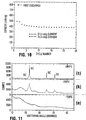
- Figures 11a, b, and c show a comparison of the powder x-ray diffraction patterns of the samples V, Va, and Vb of Inventive Example 1.
- Figures 12a, b, and c compare the voltage versus capacity profiles for the batteries comprising samples V, Va, and Vb respectively.
- Figure 13 shows the powder x-ray diffraction patterns of samples VI and IV of the Inventive Examples.
- Figure 14 shows the weight loss versus temperature curve for polyphenylsesquisiloxane as determined by TGA in Inventive Example 2.
- Figure 15 shows a comparison of the voltage versus capacity profiles for the batteries comprising comparative sample I and inventive samples III and VI.
- the carbonaceous insertion compounds of the invention comprise a pre-graphitic carbonaceous host C, atoms of an alkali metal A inserted into the host, and atoms of an element B incorporated into the host, wherein B is capable of forming alloys with A.
- the atoms of alloying element B are incorporated predominantly as monodispersed atoms in the host wherein the term monodispersed is intended to include single atoms and/or small clusters of the alloying element such that the resulting compound exhibits properties more characteristic of single atoms of the alloying element than that of a bulk compound of the alloying element.
- the amount of alloying element B present must be greater than zero.
- the structure of the carbonaceous insertion compound can be predominantly disorganized resulting in an x-ray diffraction pattern of the compound that is very poorly developed or amorphous. This suggests that the compounds are not necessarily the same as those described in the aforementioned co-pending Canadian patent application filed May 3, 1994.
- the alloying element B might be selected from the group known in the literature to alloy with lithium which includes Al, Bi, Cd, Pb, Sb, and Sn. (Members in this group are additionally known to or can be expected to alloy with other alkali metals from the Group la elements of the periodic table.)
- the preferred theoretical (based on Table 1 data) alloying element is Si.
- the alkali metal A inserted into the host might be any alkali metal.
- Certain compounds of this invention are attractive for use as anode materials in lithium ion batteries.
- the alloying atoms are silicon
- the reversible capacity of the compound of the invention can be increased over that of the carbonaceous host alone while still maintaining cycling performance similar to the carbonaceous host.
- the compounds of the invention can combine to some extent the attractive features of the capacity of the alloying element with the cycling stability of a carbonaceous compound.
- compounds of the invention may exhibit characteristics or properties that are similar to those of the carbonaceous host and/or the alloying element, the compound is not however simply a mixture of a carbonaceous host and a bulk compound of the alloying element.
- the presence of a bulk compound of the alloying element is not indicated in x-ray diffraction measurements.
- other characteristics expected of a bulk compound of the alloying element are not evident in electrochemical cycling trials.
- alloying element B in the carbonaceous insertion compound.
- other elements might also be present while still enabling use of the compound as an electrode material.
- such possibilities include silicon containing compounds having the formula A x Si y C 1-y O z H n wherein O (oxygen) and H (hydrogen) are additionally present.
- the ranges for y, z, and n in silicon containing compounds of the invention may be such that y is greater than zero and less than about 0.3, the ratio z/y is greater than or equal to zero and less than or equal to about 1.5, and n is greater than or equal to zero and less than about 0.3.
- suitable precursor polymers may have to have greater than or equal to about 3 carbon atoms per Si atom to prevent formation of SiC and less than or equal to about 1.5 oxygen atoms per carbon atom to prevent formation of SiO2 during any high temperature synthesis step.
- polymers having the formula Si y' C 1-y' O z' H n' may be suitable as precursors if y' is in the range from greater than zero to less than about 0.3 and the ratio z'/y' is less than or equal to about 1.5. It is expected however that a precursor material may lose hydrogen, oxygen, or carbon in the early stages of any high temperature synthesis step, thus being unavailable for reaction later. Thus, suitable precursor materials may have significant hydrogen content and oxygen or carbon contents that initially exceed these anticipated limits since such loss may result in the limits being met prior to reaching critical reaction temperatures.
- Polymers comprising halide ligands may also be suitable precursor polymers. It is expected that halide ligands would be substantially eliminated during pyrolysis to temperatures similar to those used in the following examples.
- Polyvinylchloride or PVC for instance retains little or no chlorine when pyrolyzed under inert gas at a temperature near 1000°C. The product exhibits an x-ray diffraction pattern characteristic of a hard carbon prepared at that temperature.
- silicon has 14 electrons per atom and carbon has only 6 electrons per atom. Since the scattered x-ray intensity from an atom is roughly proportional to the square of the number of electrons it has, the x-ray pattern should be very sensitive to the silicon. Silicon-carbon-oxygen compounds of the invention have been prepared containing substantial amounts of Si yet with no evidence of crystalline Si nor SiC nor SiO2 in the x-ray patterns. (Amorphous silicon would have been expected to crystallize at the temperatures used in the preparation.) Thus, as in the aforementioned co-pending Canadian patent application filed May 3, 1994, the silicon atoms most likely are monodispersed along with oxygen within the host carbon.
- One method for making compounds of the invention is to pyrolyze a suitable precursor or mixture of precursors that contain both carbon and the desired alloying element.
- the pyrolysis should be performed under a controlled atmosphere to prevent the formation of oxides of carbon and/or the alloying element.
- a suitable reaction system could consist of a reaction tube (quartz for example) installed in a conventional tube furnace wherein the tube has sealed inlet and outlet connections for purposes of controlling the atmosphere therein.
- the precursor/s could thus be pyrolyzed in the reaction tube under an inert gas flow or even under reduced pressure. Additionally, controlled partial reduction or oxidation can be achieved by admitting controlled amounts of an appropriate gas.
- the precursor/s should substantially pyrolyze rather than simply evaporate.
- polymer precursors seem preferred.
- Such pyrolysis is performed at a temperature above the decomposition temperature of the polymer and below the minimum of the temperatures for forming a carbide or oxide of the alloying element B.
- oxygen may be present in the polymer itself and thus may react with B to form an oxide even in the absence of oxygen gas.
- the temperature for forming said carbide or oxide will be dependent on the polymer used and thus varies accordingly. It may be advantageous to incorporate soaking periods at several temperatures as part of the heat treatment.
- a low temperature soak below about 500°C could be used to gel a polymer (if it were a liquid initially) prior to a final heating to the pyrolysis temperature.
- the heating profile can be adjusted to maximize product yield and to control the product stoichiometry.
- a suitable silicon containing polymer is obviously used in the pyrolysis.
- a precursor might be selected from the group of siloxanes having formula: wherein R, R',R'', and R''' are alkyl, aryl, or general ligands.
- R, R',R'', and R''' are alkyl, aryl, or general ligands.
- Pyrolysis temperatures in this instance were above or equal to about 900°C and below or equal to about 1100°C. It is believed however that lower pyrolysis temperatures (eg. perhaps as low as 700°C) may also be suitable.
- a successful preparation involved use of polyphenylsesquisiloxane wherein the pyrolysis temperature in this instance was about 1000°C.
- other potentially suitable silicon containing precursors include members of the groups of poly(siloxanesilphenylenes), poly(silmethylenes), polysilanes, or poly(silphenylenes). Members in each group are commercially available but the products of pyrolysis may not have been considered to be insertion compounds previously.
- Figure 1 shows the chemical structures for each of these potential precursors along with that of the aforementioned group of siloxanes and of polyphenylsesquisiloxane.
- R, R', R'', R'' in this figure denote alkyl, aryl, or general ligands in the usual notation of organic chemistry.
- the specific ligands methyl and phenyl are denoted Me and Ph respectively where appropriate.
- the silicon containing product of the aforementioned process has no alkali metal inserted as prepared.
- Alkali metal atoms, in particular Li can be inserted thereafter via chemical or electrochemical means (such as in a lithium or lithium ion battery).
- a variety of battery embodiments are possible using anode material prepared by the method of the invention.
- Miniature laboratory batteries employing a lithium metal anode are described in the examples to follow.
- a preferred construction for a lithium ion type product is that depicted for a conventional spiral-wound type battery in the cross-sectional view of Figure 2.
- a jelly roll 4 is created by spirally winding a cathode foil (not shown), an anode foil (not shown), and two microporous polyolefin sheets (not shown) that act as separators.
- Cathode foils are prepared by applying a mixture of a suitable cathode material, such as a lithiated transition metal oxide, possibly other powdered cathode material if desired, a binder, and a conductive dilutant onto a thin aluminum foil.
- a suitable cathode material such as a lithiated transition metal oxide, possibly other powdered cathode material if desired, a binder, and a conductive dilutant onto a thin aluminum foil.
- the application method first involves dissolving the binder in a suitable liquid carrier. Then, a slurry is prepared using this solution plus the other powdered solid components. The slurry is then coated uniformly onto the substrate foil. Afterwards, the carrier solvent is evaporated away. Often, both sides of the aluminum foil substrate are coated in this manner and subsequently the cathode foil is calendered.
- Anode foils are prepared in a like manner except that a powdered carbonaceous compound of the invention is used instead of the cathode material and thin copper foil is usually used instead of aluminum.
- Anode foils are typically slightly wider than the cathode foils in order to ensure that anode foil is always opposite cathode foil. This feature is illustrated with the cathode upper edge 13, cathode lower edge 14, anode upper edge 12, and anode lower edge 15 depicted in Figure 2.
- the jelly roll 4 is inserted into a conventional battery can 3.
- a header 1 and gasket 10 are used to seal the battery 16.
- the header may include safety devices if desired.
- a combination safety vent and pressure operated disconnect device may be employed.
- Figure 2 shows one such combination that is described in detail in Canadian Patent Application No. 2,099,657.
- a positive thermal coefficient device PTC may be incorporated into the header to limit the short circuit current capability of the battery.
- the external surface of the header 1 is used as the positive terminal, while the external surface of the can 3 serves as the negative terminal.
- cathode tab 5 and anode tab 6 connections are made to connect the internal electrodes to the external terminals.
- Appropriate insulating pieces 2 and 7 may be inserted to prevent the possibility of internal shorting.
- electrolyte 8 is added prior to crimping the header 1 to the can 3 in order to seal the battery.
- the types of and amounts of the component materials must be chosen based on component material properties and the desired performance and safety requirements.
- the compounds prepared in the examples to follow have significantly increased irreversible capacity for lithium along with an increased reversible capacity over that of many typical commercial carbonaceous anode materials. This must be taken into account in the battery design. Alternately, compounds with reduced irreversible capacity must be employed.
- an electrical conditioning step involving at least the first recharge of the battery, is part of the assembly process. Again, the determination of an appropriate conditioning step along with the setting of the battery operating parameters (eg. voltage, current, and temperature limits) would be required of someone familiar with the field.
- batteries of the invention are possible for the batteries of the invention.
- a prismatic format is considered highly desirable and possible.
- a miniature embodiment, eg. coin cell, is also possible and the general construction of such cells is described in the laboratory coin cell examples to follow.
- powder x-ray diffraction was used to characterize samples.
- a Seimens D5000 diffractometer equipped with a copper target x-ray tube and a diffracted beam monochromator was used for these experiments.
- the samples were made by filling a 2mm deep well in a stainless steel block with powder and levelling the surface. The samples were sometimes loosely packed, and diffraction peaks from the stainless steel holder could occasionally be observed.
- LA Laser-ablation inductively coupled mass spectroscopy
- TGA thermal gravimetric analysis
- RAA residual gas analysis
- FIG. 3 shows an exploded view of the coin cell type battery.
- the samples were used as cathodes in these batteries opposite a lithium metal anode.
- a stainless steel cap 21 and special oxidation resistant case 30 comprise the container and also serve as negative and positive terminals respectively.
- a gasket 22 is used as a seal and also serves to separate the two terminals. Mechanical pressure is applied to the stack comprising lithium anode 25, separator 26, and sample cathode 27 by means of mild steel disc spring 23 and stainless disc 24.
- the disc spring was selected such that a pressure of about 15 bar was applied following closure of the battery.
- 125 ⁇ m thick metal foil was used as the lithium anode 25.
- Celgard® 2502 microporous polypropylene film was used as the separator 26.
- the electrolyte 28 was a solution of 1M LiN(CF3SO2)2 salt dissolved in a solvent mixture of ethylene carbonate and diethyl carbonate in a volume ratio of 50/50.
- Sample cathodes 27 were made using a mixture of powdered sample compound plus Super S (trademark of Ensagri) carbon black conductive dilutant and polyvinylidene fluoride (PVDF) binder (in amounts of about 5% and 10% by weight respectively to that of the sample) uniformly coated on thin copper foil.
- the powdered sample and the carbon black were initially added to a solution of 20% PVDF in N-methylpyrollidinone (NMP) to form a slurry such that 10% of the final electrode mass would be PVDF. Excess NMP was then added until the slurry reached a smooth syrupy viscosity.
- NMP N-methylpyrollidinone
- the slurry was then spread on small preweighed pieces of Cu foil (about 1.5 cm in area) using a spreader, and the NMP was evaporated off at about 90°C in air. Once the sample cathode stock was dried, it was compressed between flat plates at about 25 bar pressure. These electrodes were then weighed and the weight of the foil, the PVDF, and the carbon black were subtracted to obtain the active electrode mass.
- the coin cell batteries were removed from the glove box, thermostatted at 30 ⁇ 1°C, and then charged and discharged using constant current cyclers with ⁇ 1% current stability. Data was logged whenever the cell voltage changed by more than 0.005 V. Currents were adjusted according to the amount of active material, depending on the desired test.
- Benzene was pyrolyzed in a CVD reactor under argon flow at 950°C.
- the fine powder product, denoted sample I was recovered and analyzed by x-ray diffraction.
- Figure 4 shows the x-ray diffraction pattern for this material, which is typical of a soft carbon prepared at this temperature (see H. Shi et al., Journal of Applied Crystallography, 26 , 827, (1993)). Well developed Bragg Peaks are clearly observed.
- the chemical composition was estimated using CHN analysis results and the assumption that no oxygen nor silicon was present in the sample (since neither element should be present in the benzene precursor) .
- the results of the chemical analysis and estimated stoichiometry are shown in the following Table 2.
- a laboratory coin cell battery was prepared using this sample as described previously. The battery was then discharged, charged, and discharged again at currents corresponding to 3.7 mA/g of sample.
- sample II Benzene and dimethyldichlorosilane were co-pyrolyzed in a CVD reactor under argon flow at 950°C.
- Figure 5 shows the x-ray diffraction pattern for sample II and is similar to that of Figure 4. Silicon is incorporated within sample II (about 6 atomic percent silicon as shown later) yet it does not affect the diffraction pattern, strongly implying that the silicon is located within the disorganized regions of the host in this case.
- the chemical composition of this sample was estimated using a TGA method and results of the CHN analysis.
- the TGA method consists of heating a sample in air to 1100°C on the balance pan of a TGA instrument and measuring the weight loss.
- the sample consists mainly of carbon and silicon.
- the results of the chemical analysis and estimated stoichiometry are shown in the following Table 2.
- Polymethylphenylsiloxane polymer precursor (Dow 710 fluid product of Dow) was pyrolyzed under flowing argon in a tube furnace apparatus as mentioned in the Description.
- the sample temperature was ramped to the soaking temperature at a rate of about 20°C/min. Thereafter, the soaking temperature was maintained for 1 hour, followed by a cool down to room temperature. The argon flow was maintained until the sample temperature fell below 100°C.
- Alumina boats were used to contain the samples in a quartz reactor tube.
- the initial sample fluid mass was near 12 grams, while about 4 grams of solid black reaction product was obtained in each case after pyrolysis. About 30% of the liquid sample is estimated to have simply evaporated before actual pyrolysis occurred.
- Figures 6a, b, and c show the powder x-ray diffraction patterns of these samples III, IV, and V respectively.
- CHN and LA analyses were performed on these samples as described previously. Additionally, the stoichiometry was estimated for each sample using the results of these analyses and the assumption that neither silicon nor oxygen was lost during pyrolysis of the polymer precursor. Thus, the silicon:oxygen ratio in the samples will be the same as that of the polymer precursor, or 1:1. (This assumption seems reasonable based on an analysis of the gaseous decomposition products during the pyrolysis.
- a small sample of polymethylphenylsiloxane was pyrolyzed in a TGA apparatus coupled to an RGA instrument.
- Figures 8a, b, and c show the voltage versus capacity profiles for the batteries comprising inventive samples III, IV, and V respectively.
- the reversible capacity is approximately maintained at higher pyrolysis temperatures while the irreversible capacity is somewhat reduced.
- the battery comprising sample V was further cycled at currents corresponding to 74 mA/g.
- Figure 9 shows the voltage versus time plot of this battery over representative cycles 10-14. The cycling behaviour is very reproducible.
- Figure 10 shows the capacity versus cycle number data for this battery.
- some of sample V was used for pyrolysis experiments at higher temperatures. 1 gram amounts were heated under flowing argon for one hour at 1300°C and at 1500°C. These samples are denoted Va and Vb respectively.
- Figures 11a, b, and c compare the x-ray diffraction patterns for samples V, Va, and Vb respectively. Silicon carbide formation is clearly detected in samples Va and Vb.
- Polyphenylsesquisiloxane solid was obtained from United Chemical Technologies Inc. 3.66 grams of this solid was pyrolyzed under argon at 1000°C in the tube furnace apparatus used for Inventive Example 1. 2.86 grams of shiny grey-black material was recovered and there was no evidence of evaporation of polymer from the boat. This sample is denoted sample VI.
- Figure 13 shows the powder x-ray diffraction patterns of sample VI and that of sample IV of Inventive Example 1. The patterns of these materials are very similar.
- FIG. 15 shows a comparison between the voltage versus capacity profiles for the batteries made with comparative sample I, inventive sample III, and inventive sample VI.
- the two inventive samples are very similar electrochemically.
Landscapes
- Chemical & Material Sciences (AREA)
- Electrochemistry (AREA)
- General Chemical & Material Sciences (AREA)
- Chemical Kinetics & Catalysis (AREA)
- Composite Materials (AREA)
- Engineering & Computer Science (AREA)
- Materials Engineering (AREA)
- Manufacturing & Machinery (AREA)
- Inorganic Chemistry (AREA)
- Battery Electrode And Active Subsutance (AREA)
- Silicon Compounds (AREA)
- Carbon And Carbon Compounds (AREA)
- Secondary Cells (AREA)
Applications Claiming Priority (2)
| Application Number | Priority Date | Filing Date | Title |
|---|---|---|---|
| CA2127621 | 1994-07-08 | ||
| CA002127621A CA2127621C (fr) | 1994-07-08 | 1994-07-08 | Composes d'insertion carbones et leur utilisation comme anodes dans les piles rechargeables |
Publications (2)
| Publication Number | Publication Date |
|---|---|
| EP0692833A1 true EP0692833A1 (fr) | 1996-01-17 |
| EP0692833B1 EP0692833B1 (fr) | 2001-11-21 |
Family
ID=4153972
Family Applications (1)
| Application Number | Title | Priority Date | Filing Date |
|---|---|---|---|
| EP95304410A Expired - Lifetime EP0692833B1 (fr) | 1994-07-08 | 1995-06-23 | Composés d'insertion carbonés et leur utilisation comme anodes dans les piles rechargeables |
Country Status (5)
| Country | Link |
|---|---|
| US (1) | US5587256A (fr) |
| EP (1) | EP0692833B1 (fr) |
| JP (1) | JPH0840716A (fr) |
| CA (1) | CA2127621C (fr) |
| DE (1) | DE69523995T2 (fr) |
Cited By (10)
| Publication number | Priority date | Publication date | Assignee | Title |
|---|---|---|---|---|
| FR2731216A1 (fr) * | 1995-03-03 | 1996-09-06 | Moli Energy Ltd | Composes d'insertion carbones et leur utilisation en tant qu'anodes dans des batteries rechargeables |
| US5631106A (en) * | 1996-06-11 | 1997-05-20 | Dow Corning Corporation | Electrodes for lithium ion batteries using polysilazanes ceramic with lithium |
| EP0813258A1 (fr) * | 1996-06-11 | 1997-12-17 | Dow Corning Corporation | Electrodes pour batteries à ions lithium fabriquées à partir de polysiloxanes |
| EP0813260A1 (fr) * | 1996-06-11 | 1997-12-17 | Dow Corning Corporation | Electrodes pour batteries à ions lithium fabriquées à partir de polysilanes |
| EP0813259A1 (fr) * | 1996-06-11 | 1997-12-17 | Dow Corning Corporation | Electrodes pour batteries à ions lithium fabriquées à partir de polysilazanes |
| EP0813257A1 (fr) * | 1996-06-11 | 1997-12-17 | Dow Corning Corporation | Electrodes contenant des polycarbosilanes pour batteries à ions lithium |
| EP0872902A1 (fr) * | 1997-04-14 | 1998-10-21 | Hydro-Quebec | Feuillard d'anode alliée et dense à relaxation locale de stress |
| EP0903795A4 (fr) * | 1996-11-26 | 2005-03-16 | Kao Corp | Materiau d'electrode negative pour pile secondaire non aqueuse |
| EP1011160A4 (fr) * | 1998-05-25 | 2007-07-18 | Kao Corp | Procede de fabrication d'electrode negative pour accumulateur electrique |
| WO2010112580A1 (fr) | 2009-04-03 | 2010-10-07 | Basf Se | Matière électroactive et son utilisation dans des anodes pour des cellules aux ions lithium |
Families Citing this family (35)
| Publication number | Priority date | Publication date | Assignee | Title |
|---|---|---|---|---|
| GB2296125B (en) * | 1994-12-16 | 1998-04-29 | Moli Energy | Pre-graphitic carbonaceous insertion compounds and use as anodes in rechargeable batteries |
| EP0903797B1 (fr) * | 1996-11-26 | 2010-06-23 | Kao Corporation | Materiau pour une electrode negative pour une pile secondaire non aqueuse et pile secondaire non aqueuse |
| CA2231665A1 (fr) * | 1997-03-25 | 1998-09-25 | Dow Corning Corporation | Procede pour la production d'un materiau destine a la fabrication d'electrodes de batteries au lithium |
| US6824920B1 (en) | 1997-06-03 | 2004-11-30 | Matsushita Electric Industrial Co., Ltd. | Non-aqueous electrolyte secondary battery comprising composite particles |
| US6090505A (en) * | 1997-06-03 | 2000-07-18 | Matsushita Electric Industrial Co., Ltd. | Negative electrode materials for non-aqueous electrolyte secondary batteries and said batteries employing the same materials |
| US6143448A (en) * | 1997-10-20 | 2000-11-07 | Mitsubishi Chemical Corporation | Electrode materials having carbon particles with nano-sized inclusions therewithin and an associated electrolytic and fabrication process |
| US5965297A (en) * | 1997-10-20 | 1999-10-12 | Mitsubhish Chemical Corporation | Electrode materials having carbon particles with nano-sized inclusions therewithin and an associated electrochemical and fabrication process |
| US6653019B1 (en) | 1998-06-03 | 2003-11-25 | Matsushita Electric Industrial Co., Ltd. | Non-aqueous electrolyte secondary cell |
| US6821675B1 (en) | 1998-06-03 | 2004-11-23 | Matsushita Electric Industrial Co., Ltd. | Non-Aqueous electrolyte secondary battery comprising composite particles |
| WO2000033404A1 (fr) * | 1998-12-03 | 2000-06-08 | Kao Corporation | Pile secondaire au lithium et son procede de fabrication |
| US6485864B1 (en) | 1999-02-26 | 2002-11-26 | Adchemco Corporation | Production process of material for lithium-ion secondary batteries, material obtained by the process, and batteries |
| US6334939B1 (en) | 2000-06-15 | 2002-01-01 | The University Of North Carolina At Chapel Hill | Nanostructure-based high energy capacity material |
| US6706447B2 (en) | 2000-12-22 | 2004-03-16 | Fmc Corporation, Lithium Division | Lithium metal dispersion in secondary battery anodes |
| US7276314B2 (en) | 2000-12-22 | 2007-10-02 | Fmc Corporation | Lithium metal dispersion in secondary battery anodes |
| US20020155342A1 (en) * | 2001-04-06 | 2002-10-24 | Ballard Power Systems Inc. | High utilization supported catalyst compositions with improved resistance to poisoning and corrosion |
| US20050130043A1 (en) * | 2003-07-29 | 2005-06-16 | Yuan Gao | Lithium metal dispersion in electrodes |
| GB0318942D0 (en) * | 2003-08-13 | 2003-09-17 | Aea Technology Battery Systems | Process for producing an electrode |
| JP4920880B2 (ja) * | 2003-09-26 | 2012-04-18 | 三星エスディアイ株式会社 | リチウムイオン二次電池 |
| US8231810B2 (en) | 2004-04-15 | 2012-07-31 | Fmc Corporation | Composite materials of nano-dispersed silicon and tin and methods of making the same |
| GB0414161D0 (en) * | 2004-06-24 | 2004-07-28 | Aea Technology Battery Systems | Anode for lithium ion cell |
| US7771874B2 (en) | 2005-06-29 | 2010-08-10 | Fmc Corporation | Lithium manganese compounds and methods of making the same |
| US7588623B2 (en) * | 2005-07-05 | 2009-09-15 | Fmc Corporation Lithium Division | Stabilized lithium metal powder for li-ion application, composition and process |
| US20070077496A1 (en) * | 2005-10-05 | 2007-04-05 | Medtronic, Inc. | Lithium-ion battery |
| US7906238B2 (en) * | 2005-12-23 | 2011-03-15 | 3M Innovative Properties Company | Silicon-containing alloys useful as electrodes for lithium-ion batteries |
| US20070190422A1 (en) * | 2006-02-15 | 2007-08-16 | Fmc Corporation | Carbon nanotube lithium metal powder battery |
| JP5003877B2 (ja) * | 2006-03-27 | 2012-08-15 | 信越化学工業株式会社 | SiCO−Li系複合体の製造方法 |
| US20090035663A1 (en) | 2006-10-13 | 2009-02-05 | Fmc Corporation, Lithium Division | Stabilized lithium metal powder for li-ion application, composition and process |
| US8021496B2 (en) | 2007-05-16 | 2011-09-20 | Fmc Corporation | Stabilized lithium metal powder for Li-ion application, composition and process |
| US20090061321A1 (en) * | 2007-08-31 | 2009-03-05 | Fmc Corporation, Lithium Division | Stabilized lithium metal powder for li-ion application, composition and process |
| WO2009033015A1 (fr) * | 2007-09-07 | 2009-03-12 | Inorganic Specialists, Inc. | Papier nanofibre modifié au silicium comme matériau d'anode pour une batterie au lithium secondaire |
| US20110135810A1 (en) * | 2009-12-03 | 2011-06-09 | Marina Yakovleva | Finely deposited lithium metal powder |
| JP5411781B2 (ja) * | 2010-04-05 | 2014-02-12 | 信越化学工業株式会社 | 非水電解質二次電池用負極材及び非水電解質二次電池用負極材の製造方法並びにリチウムイオン二次電池 |
| JP5411780B2 (ja) * | 2010-04-05 | 2014-02-12 | 信越化学工業株式会社 | 非水電解質二次電池用負極材及び非水電解質二次電池用負極材の製造方法並びにリチウムイオン二次電池 |
| KR20150098610A (ko) | 2012-12-19 | 2015-08-28 | 디아이씨 가부시끼가이샤 | 비수성 이차 전지 부극용 활물질 및 비수성 이차 전지 |
| EP3089245B1 (fr) * | 2013-12-25 | 2019-01-30 | Shin-Etsu Chemical Co., Ltd. | Matériau actif d'électrode négative pour batteries secondaires à électrolyte non aqueux et son procédé de production |
Citations (10)
| Publication number | Priority date | Publication date | Assignee | Title |
|---|---|---|---|---|
| JPH03225750A (ja) * | 1990-01-30 | 1991-10-04 | Bridgestone Corp | リチウム電池用正極シート |
| JPH03245458A (ja) | 1990-02-21 | 1991-11-01 | Sony Corp | 電池用負極およびその製造方法ならびにこれを用いた非水電解液電池 |
| EP0460617A2 (fr) * | 1990-06-04 | 1991-12-11 | Mitsubishi Petrochemical Co., Ltd. | Electrode à base de métal alcalin pour une pile secondaire |
| EP0486950A1 (fr) | 1990-11-17 | 1992-05-27 | Sony Corporation | Batterie secondaire à électrolyte non aqueux |
| US5130211A (en) | 1990-10-24 | 1992-07-14 | Her Majesty The Queen In Right Of The Provence Of British Columbia | Electrolyte solution sequestering agents for electrochemical cells having carbonaceous electrodes |
| JPH0582130A (ja) * | 1991-09-24 | 1993-04-02 | Sanyo Electric Co Ltd | 非水系二次電池 |
| EP0549802A1 (fr) * | 1991-06-20 | 1993-07-07 | Mitsubishi Chemical Corporation | Electrode pour pile secondaire |
| JPH05182668A (ja) * | 1991-12-27 | 1993-07-23 | Sanyo Electric Co Ltd | 非水系電解質二次電池 |
| JPH0696759A (ja) * | 1992-08-26 | 1994-04-08 | Seiko Instr Inc | 非水電解質二次電池及びそれに用いる活物質の製造方法 |
| CA2098248A1 (fr) | 1993-06-11 | 1994-12-12 | Jeffrey Raymond Dahn | Materiau carbone dans lequel on a remplace des atomes de carbone par des atomes de bore, servant d'anodes dans des batteries rechargeables au lithium |
Family Cites Families (4)
| Publication number | Priority date | Publication date | Assignee | Title |
|---|---|---|---|---|
| JP2674793B2 (ja) * | 1988-08-31 | 1997-11-12 | ソニー 株式会社 | 非水電解液電池 |
| JP2997741B2 (ja) * | 1992-07-29 | 2000-01-11 | セイコーインスツルメンツ株式会社 | 非水電解質二次電池及びその製造方法 |
| JP3010226B2 (ja) * | 1993-03-10 | 2000-02-21 | セイコーインスツルメンツ株式会社 | 非水電解質二次電池及びその製造方法 |
| CA2122770C (fr) * | 1994-05-03 | 2000-10-03 | Moli Energy (1990) Limited | Substances carbonees hotes et leur utilisation comme anodes dans les piles rechargeables |
-
1994
- 1994-07-08 CA CA002127621A patent/CA2127621C/fr not_active Expired - Fee Related
-
1995
- 1995-04-25 US US08/428,042 patent/US5587256A/en not_active Expired - Lifetime
- 1995-06-23 EP EP95304410A patent/EP0692833B1/fr not_active Expired - Lifetime
- 1995-06-23 DE DE69523995T patent/DE69523995T2/de not_active Expired - Fee Related
- 1995-06-29 JP JP7164100A patent/JPH0840716A/ja active Pending
Patent Citations (11)
| Publication number | Priority date | Publication date | Assignee | Title |
|---|---|---|---|---|
| JPH03225750A (ja) * | 1990-01-30 | 1991-10-04 | Bridgestone Corp | リチウム電池用正極シート |
| JPH03245458A (ja) | 1990-02-21 | 1991-11-01 | Sony Corp | 電池用負極およびその製造方法ならびにこれを用いた非水電解液電池 |
| EP0460617A2 (fr) * | 1990-06-04 | 1991-12-11 | Mitsubishi Petrochemical Co., Ltd. | Electrode à base de métal alcalin pour une pile secondaire |
| US5130211A (en) | 1990-10-24 | 1992-07-14 | Her Majesty The Queen In Right Of The Provence Of British Columbia | Electrolyte solution sequestering agents for electrochemical cells having carbonaceous electrodes |
| EP0486950A1 (fr) | 1990-11-17 | 1992-05-27 | Sony Corporation | Batterie secondaire à électrolyte non aqueux |
| EP0549802A1 (fr) * | 1991-06-20 | 1993-07-07 | Mitsubishi Chemical Corporation | Electrode pour pile secondaire |
| JPH0582130A (ja) * | 1991-09-24 | 1993-04-02 | Sanyo Electric Co Ltd | 非水系二次電池 |
| JPH05182668A (ja) * | 1991-12-27 | 1993-07-23 | Sanyo Electric Co Ltd | 非水系電解質二次電池 |
| JPH0696759A (ja) * | 1992-08-26 | 1994-04-08 | Seiko Instr Inc | 非水電解質二次電池及びそれに用いる活物質の製造方法 |
| CA2098248A1 (fr) | 1993-06-11 | 1994-12-12 | Jeffrey Raymond Dahn | Materiau carbone dans lequel on a remplace des atomes de carbone par des atomes de bore, servant d'anodes dans des batteries rechargeables au lithium |
| EP0629012A2 (fr) * | 1993-06-11 | 1994-12-14 | Moli Energy (1990) Limited | Matériau en carbone présentant comme substituants des récepteurs d'électrons pour utilisation comme anodes dans des piles rechargeables au lithium |
Non-Patent Citations (10)
| Title |
|---|
| "6th International Lithium Battery Conference", 13 May 1992, article MATSUSHITA |
| CHEMICAL ABSTRACTS, vol. 119, no. 6, 9 August 1993, Columbus, Ohio, US; abstract no. 52913v * |
| J. R. DAHN ET AL.: "BORON SUBSTITUTED CARBONS AS ANODES FOR LITHIUM ION CELLS", EXTENDED ABSTRACTS, no. 20, October 1993 (1993-10-01), PRINCETON, NEW JERSEY US, pages 34, XP000422218 * |
| J. R. DAHN ET AL.: "THE EFFECT OF BORON SUBSTITUTION IN CARBON ON THE INTERCALATION OF LITHIUM IN LIx(BzC1-z)6", J. ELECTROCHEM. SOC., vol. 141, no. 4, April 1994 (1994-04-01), pages 907 - 912 * |
| K. SATO ET AL., SCIENCE, vol. 264, 1994, pages 556 |
| PATENT ABSTRACTS OF JAPAN vol. 15, no. 510 (E - 1149) 25 December 1991 (1991-12-25) * |
| PATENT ABSTRACTS OF JAPAN vol. 16, no. 37 (E - 1160) 29 January 1992 (1992-01-29) * |
| PATENT ABSTRACTS OF JAPAN vol. 17, no. 411 (E - 1406) * |
| PATENT ABSTRACTS OF JAPAN vol. 17, no. 593 (E - 1454) 28 October 1993 (1993-10-28) * |
| PATENT ABSTRACTS OF JAPAN vol. 18, no. 355 (E - 1573) 5 July 1994 (1994-07-05) * |
Cited By (14)
| Publication number | Priority date | Publication date | Assignee | Title |
|---|---|---|---|---|
| FR2731216A1 (fr) * | 1995-03-03 | 1996-09-06 | Moli Energy Ltd | Composes d'insertion carbones et leur utilisation en tant qu'anodes dans des batteries rechargeables |
| US5824280A (en) * | 1996-06-11 | 1998-10-20 | Dow Corning Corporation | Electrodes for lithium ion batteries using polysiloxanes |
| EP0813258A1 (fr) * | 1996-06-11 | 1997-12-17 | Dow Corning Corporation | Electrodes pour batteries à ions lithium fabriquées à partir de polysiloxanes |
| EP0813260A1 (fr) * | 1996-06-11 | 1997-12-17 | Dow Corning Corporation | Electrodes pour batteries à ions lithium fabriquées à partir de polysilanes |
| EP0813259A1 (fr) * | 1996-06-11 | 1997-12-17 | Dow Corning Corporation | Electrodes pour batteries à ions lithium fabriquées à partir de polysilazanes |
| EP0813257A1 (fr) * | 1996-06-11 | 1997-12-17 | Dow Corning Corporation | Electrodes contenant des polycarbosilanes pour batteries à ions lithium |
| US5631106A (en) * | 1996-06-11 | 1997-05-20 | Dow Corning Corporation | Electrodes for lithium ion batteries using polysilazanes ceramic with lithium |
| US5907899A (en) * | 1996-06-11 | 1999-06-01 | Dow Corning Corporation | Method of forming electrodes for lithium ion batteries using polycarbosilanes |
| US6306541B1 (en) | 1996-06-11 | 2001-10-23 | Dow Corning Corporation | Electrodes for lithium ion batteries using polysilanes |
| EP0903795A4 (fr) * | 1996-11-26 | 2005-03-16 | Kao Corp | Materiau d'electrode negative pour pile secondaire non aqueuse |
| EP0872902A1 (fr) * | 1997-04-14 | 1998-10-21 | Hydro-Quebec | Feuillard d'anode alliée et dense à relaxation locale de stress |
| EP1011160A4 (fr) * | 1998-05-25 | 2007-07-18 | Kao Corp | Procede de fabrication d'electrode negative pour accumulateur electrique |
| WO2010112580A1 (fr) | 2009-04-03 | 2010-10-07 | Basf Se | Matière électroactive et son utilisation dans des anodes pour des cellules aux ions lithium |
| US8992801B2 (en) | 2009-04-03 | 2015-03-31 | Basf Se | Electroactive material, and use thereof in anodes for lithium-ion cells |
Also Published As
| Publication number | Publication date |
|---|---|
| DE69523995T2 (de) | 2002-06-27 |
| EP0692833B1 (fr) | 2001-11-21 |
| US5587256A (en) | 1996-12-24 |
| JPH0840716A (ja) | 1996-02-13 |
| CA2127621C (fr) | 1999-12-07 |
| CA2127621A1 (fr) | 1996-01-09 |
| DE69523995D1 (de) | 2002-01-03 |
Similar Documents
| Publication | Publication Date | Title |
|---|---|---|
| US5587256A (en) | Carbonaceous insertion compounds and use as anodes in rechargeable batteries | |
| CA2122770C (fr) | Substances carbonees hotes et leur utilisation comme anodes dans les piles rechargeables | |
| US5698340A (en) | Carbonaceous insertion compounds and use as anodes in rechargeable batteries | |
| CA2098248C (fr) | Materiau carbone dans lequel on a remplace des atomes de carbone par des atomes de bore, servant d'anodes dans des batteries rechargeables au lithium | |
| Peled et al. | SEI: past, present and future | |
| US5882218A (en) | Lithium manganese oxide insertion compounds and use in rechargeable batteries | |
| US5631104A (en) | High voltage insertion compounds for lithium batteries | |
| Yoshio et al. | Carbon-coated Si as a lithium-ion battery anode material | |
| EP0856901B1 (fr) | Additifs pour améliorer la durée de vie cyclique de batteries rechargeables non aqueuses au lithium | |
| JP4511343B2 (ja) | リチウム電池用正極材料およびその製造法 | |
| EP0998763A1 (fr) | Cellule electrochimique a ion de lithium | |
| JP5172564B2 (ja) | 非水電解質二次電池 | |
| EP0867958A1 (fr) | Procédé pour la fabrication d'une éléctrode céramique à base de SiOC et batterie rechargeable à ions lithium la contenant comme anode | |
| JP4519956B2 (ja) | 有機電解液及びこれを採用したリチウム2次電池 | |
| Yang et al. | Tin‐Containing Anode Materials in Combination with Li2. 6Co0. 4 N for Irreversibility Compensation | |
| JPH09245830A (ja) | 非水電解液二次電池 | |
| Wakihara et al. | A rechargeable lithium battery employing a porous thin film of Cu3+ δMo6S7. 9 | |
| KR20260029290A (ko) | 양극 조성물 | |
| CA2138360A1 (fr) | Composes d'insertion carbonaces pre-graphitiques et utilisation comme anodes dans des piles rechargeables |
Legal Events
| Date | Code | Title | Description |
|---|---|---|---|
| PUAI | Public reference made under article 153(3) epc to a published international application that has entered the european phase |
Free format text: ORIGINAL CODE: 0009012 |
|
| AK | Designated contracting states |
Kind code of ref document: A1 Designated state(s): DE FR GB |
|
| 17P | Request for examination filed |
Effective date: 19960627 |
|
| 17Q | First examination report despatched |
Effective date: 19970418 |
|
| GRAG | Despatch of communication of intention to grant |
Free format text: ORIGINAL CODE: EPIDOS AGRA |
|
| GRAG | Despatch of communication of intention to grant |
Free format text: ORIGINAL CODE: EPIDOS AGRA |
|
| GRAH | Despatch of communication of intention to grant a patent |
Free format text: ORIGINAL CODE: EPIDOS IGRA |
|
| GRAH | Despatch of communication of intention to grant a patent |
Free format text: ORIGINAL CODE: EPIDOS IGRA |
|
| GRAA | (expected) grant |
Free format text: ORIGINAL CODE: 0009210 |
|
| AK | Designated contracting states |
Kind code of ref document: B1 Designated state(s): DE FR GB |
|
| REG | Reference to a national code |
Ref country code: GB Ref legal event code: IF02 |
|
| REF | Corresponds to: |
Ref document number: 69523995 Country of ref document: DE Date of ref document: 20020103 |
|
| PG25 | Lapsed in a contracting state [announced via postgrant information from national office to epo] |
Ref country code: GB Free format text: LAPSE BECAUSE OF NON-PAYMENT OF DUE FEES Effective date: 20020623 |
|
| PLBE | No opposition filed within time limit |
Free format text: ORIGINAL CODE: 0009261 |
|
| STAA | Information on the status of an ep patent application or granted ep patent |
Free format text: STATUS: NO OPPOSITION FILED WITHIN TIME LIMIT |
|
| 26N | No opposition filed | ||
| PG25 | Lapsed in a contracting state [announced via postgrant information from national office to epo] |
Ref country code: DE Free format text: LAPSE BECAUSE OF NON-PAYMENT OF DUE FEES Effective date: 20030101 |
|
| GBPC | Gb: european patent ceased through non-payment of renewal fee |
Effective date: 20020623 |
|
| PG25 | Lapsed in a contracting state [announced via postgrant information from national office to epo] |
Ref country code: FR Free format text: LAPSE BECAUSE OF NON-PAYMENT OF DUE FEES Effective date: 20030228 |
|
| REG | Reference to a national code |
Ref country code: FR Ref legal event code: ST |