EP0693652A2 - Elektroschweissmuffe - Google Patents
Elektroschweissmuffe Download PDFInfo
- Publication number
- EP0693652A2 EP0693652A2 EP95111534A EP95111534A EP0693652A2 EP 0693652 A2 EP0693652 A2 EP 0693652A2 EP 95111534 A EP95111534 A EP 95111534A EP 95111534 A EP95111534 A EP 95111534A EP 0693652 A2 EP0693652 A2 EP 0693652A2
- Authority
- EP
- European Patent Office
- Prior art keywords
- cylindrical member
- outer cylindrical
- pipe joint
- thermoplastic resin
- inner cylindrical
- Prior art date
- Legal status (The legal status is an assumption and is not a legal conclusion. Google has not performed a legal analysis and makes no representation as to the accuracy of the status listed.)
- Granted
Links
- 238000003466 welding Methods 0.000 title claims abstract description 70
- 238000001746 injection moulding Methods 0.000 claims abstract description 60
- 229920005992 thermoplastic resin Polymers 0.000 claims abstract description 58
- 238000010438 heat treatment Methods 0.000 claims abstract description 32
- 238000004804 winding Methods 0.000 claims abstract description 5
- 229920005989 resin Polymers 0.000 claims description 37
- 239000011347 resin Substances 0.000 claims description 37
- 238000000034 method Methods 0.000 claims description 25
- 230000001360 synchronised effect Effects 0.000 claims description 10
- 238000004519 manufacturing process Methods 0.000 claims description 6
- 238000001816 cooling Methods 0.000 description 14
- 238000002347 injection Methods 0.000 description 13
- 239000007924 injection Substances 0.000 description 13
- -1 polyethylene Polymers 0.000 description 7
- 238000000465 moulding Methods 0.000 description 6
- 239000004033 plastic Substances 0.000 description 6
- 229920003023 plastic Polymers 0.000 description 6
- 239000004698 Polyethylene Substances 0.000 description 5
- 230000007547 defect Effects 0.000 description 5
- 229920000573 polyethylene Polymers 0.000 description 5
- 238000007796 conventional method Methods 0.000 description 3
- 238000007711 solidification Methods 0.000 description 3
- 230000008023 solidification Effects 0.000 description 3
- 230000004927 fusion Effects 0.000 description 2
- 239000004743 Polypropylene Substances 0.000 description 1
- 230000015572 biosynthetic process Effects 0.000 description 1
- 239000006229 carbon black Substances 0.000 description 1
- 230000003247 decreasing effect Effects 0.000 description 1
- 238000006073 displacement reaction Methods 0.000 description 1
- 230000001788 irregular Effects 0.000 description 1
- 238000005259 measurement Methods 0.000 description 1
- 238000002844 melting Methods 0.000 description 1
- 230000008018 melting Effects 0.000 description 1
- 229920001748 polybutylene Polymers 0.000 description 1
- 229920013716 polyethylene resin Polymers 0.000 description 1
- 229920001155 polypropylene Polymers 0.000 description 1
- 229920000915 polyvinyl chloride Polymers 0.000 description 1
- 239000004800 polyvinyl chloride Substances 0.000 description 1
- 229920001169 thermoplastic Polymers 0.000 description 1
- 239000004416 thermosoftening plastic Substances 0.000 description 1
- XLYOFNOQVPJJNP-UHFFFAOYSA-N water Substances O XLYOFNOQVPJJNP-UHFFFAOYSA-N 0.000 description 1
Images


Classifications
-
- B—PERFORMING OPERATIONS; TRANSPORTING
- B29—WORKING OF PLASTICS; WORKING OF SUBSTANCES IN A PLASTIC STATE IN GENERAL
- B29D—PRODUCING PARTICULAR ARTICLES FROM PLASTICS OR FROM SUBSTANCES IN A PLASTIC STATE
- B29D23/00—Producing tubular articles
- B29D23/001—Pipes; Pipe joints
- B29D23/003—Pipe joints, e.g. straight joints
- B29D23/005—Pipe joints, e.g. straight joints provided with electrical wiring
-
- B—PERFORMING OPERATIONS; TRANSPORTING
- B29—WORKING OF PLASTICS; WORKING OF SUBSTANCES IN A PLASTIC STATE IN GENERAL
- B29C—SHAPING OR JOINING OF PLASTICS; SHAPING OF MATERIAL IN A PLASTIC STATE, NOT OTHERWISE PROVIDED FOR; AFTER-TREATMENT OF THE SHAPED PRODUCTS, e.g. REPAIRING
- B29C45/00—Injection moulding, i.e. forcing the required volume of moulding material through a nozzle into a closed mould; Apparatus therefor
- B29C45/16—Making multilayered or multicoloured articles
- B29C45/1671—Making multilayered or multicoloured articles with an insert
-
- B—PERFORMING OPERATIONS; TRANSPORTING
- B29—WORKING OF PLASTICS; WORKING OF SUBSTANCES IN A PLASTIC STATE IN GENERAL
- B29C—SHAPING OR JOINING OF PLASTICS; SHAPING OF MATERIAL IN A PLASTIC STATE, NOT OTHERWISE PROVIDED FOR; AFTER-TREATMENT OF THE SHAPED PRODUCTS, e.g. REPAIRING
- B29C65/00—Joining or sealing of preformed parts, e.g. welding of plastics materials; Apparatus therefor
- B29C65/02—Joining or sealing of preformed parts, e.g. welding of plastics materials; Apparatus therefor by heating, with or without pressure
- B29C65/34—Joining or sealing of preformed parts, e.g. welding of plastics materials; Apparatus therefor by heating, with or without pressure using heated elements which remain in the joint, e.g. "verlorenes Schweisselement"
- B29C65/3404—Joining or sealing of preformed parts, e.g. welding of plastics materials; Apparatus therefor by heating, with or without pressure using heated elements which remain in the joint, e.g. "verlorenes Schweisselement" characterised by the type of heated elements which remain in the joint
- B29C65/342—Joining or sealing of preformed parts, e.g. welding of plastics materials; Apparatus therefor by heating, with or without pressure using heated elements which remain in the joint, e.g. "verlorenes Schweisselement" characterised by the type of heated elements which remain in the joint comprising at least a single wire, e.g. in the form of a winding
-
- B—PERFORMING OPERATIONS; TRANSPORTING
- B29—WORKING OF PLASTICS; WORKING OF SUBSTANCES IN A PLASTIC STATE IN GENERAL
- B29C—SHAPING OR JOINING OF PLASTICS; SHAPING OF MATERIAL IN A PLASTIC STATE, NOT OTHERWISE PROVIDED FOR; AFTER-TREATMENT OF THE SHAPED PRODUCTS, e.g. REPAIRING
- B29C65/00—Joining or sealing of preformed parts, e.g. welding of plastics materials; Apparatus therefor
- B29C65/02—Joining or sealing of preformed parts, e.g. welding of plastics materials; Apparatus therefor by heating, with or without pressure
- B29C65/34—Joining or sealing of preformed parts, e.g. welding of plastics materials; Apparatus therefor by heating, with or without pressure using heated elements which remain in the joint, e.g. "verlorenes Schweisselement"
- B29C65/3468—Joining or sealing of preformed parts, e.g. welding of plastics materials; Apparatus therefor by heating, with or without pressure using heated elements which remain in the joint, e.g. "verlorenes Schweisselement" characterised by the means for supplying heat to said heated elements which remain in the join, e.g. special electrical connectors of windings
-
- B—PERFORMING OPERATIONS; TRANSPORTING
- B29—WORKING OF PLASTICS; WORKING OF SUBSTANCES IN A PLASTIC STATE IN GENERAL
- B29C—SHAPING OR JOINING OF PLASTICS; SHAPING OF MATERIAL IN A PLASTIC STATE, NOT OTHERWISE PROVIDED FOR; AFTER-TREATMENT OF THE SHAPED PRODUCTS, e.g. REPAIRING
- B29C65/00—Joining or sealing of preformed parts, e.g. welding of plastics materials; Apparatus therefor
- B29C65/02—Joining or sealing of preformed parts, e.g. welding of plastics materials; Apparatus therefor by heating, with or without pressure
- B29C65/34—Joining or sealing of preformed parts, e.g. welding of plastics materials; Apparatus therefor by heating, with or without pressure using heated elements which remain in the joint, e.g. "verlorenes Schweisselement"
- B29C65/3472—Joining or sealing of preformed parts, e.g. welding of plastics materials; Apparatus therefor by heating, with or without pressure using heated elements which remain in the joint, e.g. "verlorenes Schweisselement" characterised by the composition of the heated elements which remain in the joint
- B29C65/3476—Joining or sealing of preformed parts, e.g. welding of plastics materials; Apparatus therefor by heating, with or without pressure using heated elements which remain in the joint, e.g. "verlorenes Schweisselement" characterised by the composition of the heated elements which remain in the joint being metallic
-
- B—PERFORMING OPERATIONS; TRANSPORTING
- B29—WORKING OF PLASTICS; WORKING OF SUBSTANCES IN A PLASTIC STATE IN GENERAL
- B29C—SHAPING OR JOINING OF PLASTICS; SHAPING OF MATERIAL IN A PLASTIC STATE, NOT OTHERWISE PROVIDED FOR; AFTER-TREATMENT OF THE SHAPED PRODUCTS, e.g. REPAIRING
- B29C66/00—General aspects of processes or apparatus for joining preformed parts
- B29C66/01—General aspects dealing with the joint area or with the area to be joined
- B29C66/05—Particular design of joint configurations
- B29C66/10—Particular design of joint configurations particular design of the joint cross-sections
- B29C66/11—Joint cross-sections comprising a single joint-segment, i.e. one of the parts to be joined comprising a single joint-segment in the joint cross-section
- B29C66/112—Single lapped joints
- B29C66/1122—Single lap to lap joints, i.e. overlap joints
-
- B—PERFORMING OPERATIONS; TRANSPORTING
- B29—WORKING OF PLASTICS; WORKING OF SUBSTANCES IN A PLASTIC STATE IN GENERAL
- B29C—SHAPING OR JOINING OF PLASTICS; SHAPING OF MATERIAL IN A PLASTIC STATE, NOT OTHERWISE PROVIDED FOR; AFTER-TREATMENT OF THE SHAPED PRODUCTS, e.g. REPAIRING
- B29C66/00—General aspects of processes or apparatus for joining preformed parts
- B29C66/50—General aspects of joining tubular articles; General aspects of joining long products, i.e. bars or profiled elements; General aspects of joining single elements to tubular articles, hollow articles or bars; General aspects of joining several hollow-preforms to form hollow or tubular articles
- B29C66/51—Joining tubular articles, profiled elements or bars; Joining single elements to tubular articles, hollow articles or bars; Joining several hollow-preforms to form hollow or tubular articles
- B29C66/52—Joining tubular articles, bars or profiled elements
- B29C66/522—Joining tubular articles
- B29C66/5221—Joining tubular articles for forming coaxial connections, i.e. the tubular articles to be joined forming a zero angle relative to each other
-
- B—PERFORMING OPERATIONS; TRANSPORTING
- B29—WORKING OF PLASTICS; WORKING OF SUBSTANCES IN A PLASTIC STATE IN GENERAL
- B29C—SHAPING OR JOINING OF PLASTICS; SHAPING OF MATERIAL IN A PLASTIC STATE, NOT OTHERWISE PROVIDED FOR; AFTER-TREATMENT OF THE SHAPED PRODUCTS, e.g. REPAIRING
- B29C66/00—General aspects of processes or apparatus for joining preformed parts
- B29C66/50—General aspects of joining tubular articles; General aspects of joining long products, i.e. bars or profiled elements; General aspects of joining single elements to tubular articles, hollow articles or bars; General aspects of joining several hollow-preforms to form hollow or tubular articles
- B29C66/51—Joining tubular articles, profiled elements or bars; Joining single elements to tubular articles, hollow articles or bars; Joining several hollow-preforms to form hollow or tubular articles
- B29C66/52—Joining tubular articles, bars or profiled elements
- B29C66/522—Joining tubular articles
- B29C66/5229—Joining tubular articles involving the use of a socket
-
- B—PERFORMING OPERATIONS; TRANSPORTING
- B29—WORKING OF PLASTICS; WORKING OF SUBSTANCES IN A PLASTIC STATE IN GENERAL
- B29C—SHAPING OR JOINING OF PLASTICS; SHAPING OF MATERIAL IN A PLASTIC STATE, NOT OTHERWISE PROVIDED FOR; AFTER-TREATMENT OF THE SHAPED PRODUCTS, e.g. REPAIRING
- B29C66/00—General aspects of processes or apparatus for joining preformed parts
- B29C66/70—General aspects of processes or apparatus for joining preformed parts characterised by the composition, physical properties or the structure of the material of the parts to be joined; Joining with non-plastics material
- B29C66/72—General aspects of processes or apparatus for joining preformed parts characterised by the composition, physical properties or the structure of the material of the parts to be joined; Joining with non-plastics material characterised by the structure of the material of the parts to be joined
- B29C66/723—General aspects of processes or apparatus for joining preformed parts characterised by the composition, physical properties or the structure of the material of the parts to be joined; Joining with non-plastics material characterised by the structure of the material of the parts to be joined being multi-layered
-
- F—MECHANICAL ENGINEERING; LIGHTING; HEATING; WEAPONS; BLASTING
- F16—ENGINEERING ELEMENTS AND UNITS; GENERAL MEASURES FOR PRODUCING AND MAINTAINING EFFECTIVE FUNCTIONING OF MACHINES OR INSTALLATIONS; THERMAL INSULATION IN GENERAL
- F16L—PIPES; JOINTS OR FITTINGS FOR PIPES; SUPPORTS FOR PIPES, CABLES OR PROTECTIVE TUBING; MEANS FOR THERMAL INSULATION IN GENERAL
- F16L47/00—Connecting arrangements or other fittings specially adapted to be made of plastics or to be used with pipes made of plastics
- F16L47/02—Welded joints; Adhesive joints
- F16L47/03—Welded joints with an electrical resistance incorporated in the joint
-
- B—PERFORMING OPERATIONS; TRANSPORTING
- B29—WORKING OF PLASTICS; WORKING OF SUBSTANCES IN A PLASTIC STATE IN GENERAL
- B29C—SHAPING OR JOINING OF PLASTICS; SHAPING OF MATERIAL IN A PLASTIC STATE, NOT OTHERWISE PROVIDED FOR; AFTER-TREATMENT OF THE SHAPED PRODUCTS, e.g. REPAIRING
- B29C65/00—Joining or sealing of preformed parts, e.g. welding of plastics materials; Apparatus therefor
- B29C65/02—Joining or sealing of preformed parts, e.g. welding of plastics materials; Apparatus therefor by heating, with or without pressure
- B29C65/34—Joining or sealing of preformed parts, e.g. welding of plastics materials; Apparatus therefor by heating, with or without pressure using heated elements which remain in the joint, e.g. "verlorenes Schweisselement"
- B29C65/3472—Joining or sealing of preformed parts, e.g. welding of plastics materials; Apparatus therefor by heating, with or without pressure using heated elements which remain in the joint, e.g. "verlorenes Schweisselement" characterised by the composition of the heated elements which remain in the joint
- B29C65/3476—Joining or sealing of preformed parts, e.g. welding of plastics materials; Apparatus therefor by heating, with or without pressure using heated elements which remain in the joint, e.g. "verlorenes Schweisselement" characterised by the composition of the heated elements which remain in the joint being metallic
- B29C65/348—Joining or sealing of preformed parts, e.g. welding of plastics materials; Apparatus therefor by heating, with or without pressure using heated elements which remain in the joint, e.g. "verlorenes Schweisselement" characterised by the composition of the heated elements which remain in the joint being metallic with a polymer coating
-
- B—PERFORMING OPERATIONS; TRANSPORTING
- B29—WORKING OF PLASTICS; WORKING OF SUBSTANCES IN A PLASTIC STATE IN GENERAL
- B29C—SHAPING OR JOINING OF PLASTICS; SHAPING OF MATERIAL IN A PLASTIC STATE, NOT OTHERWISE PROVIDED FOR; AFTER-TREATMENT OF THE SHAPED PRODUCTS, e.g. REPAIRING
- B29C66/00—General aspects of processes or apparatus for joining preformed parts
- B29C66/70—General aspects of processes or apparatus for joining preformed parts characterised by the composition, physical properties or the structure of the material of the parts to be joined; Joining with non-plastics material
- B29C66/72—General aspects of processes or apparatus for joining preformed parts characterised by the composition, physical properties or the structure of the material of the parts to be joined; Joining with non-plastics material characterised by the structure of the material of the parts to be joined
- B29C66/723—General aspects of processes or apparatus for joining preformed parts characterised by the composition, physical properties or the structure of the material of the parts to be joined; Joining with non-plastics material characterised by the structure of the material of the parts to be joined being multi-layered
- B29C66/7234—General aspects of processes or apparatus for joining preformed parts characterised by the composition, physical properties or the structure of the material of the parts to be joined; Joining with non-plastics material characterised by the structure of the material of the parts to be joined being multi-layered comprising a barrier layer
- B29C66/72341—General aspects of processes or apparatus for joining preformed parts characterised by the composition, physical properties or the structure of the material of the parts to be joined; Joining with non-plastics material characterised by the structure of the material of the parts to be joined being multi-layered comprising a barrier layer for gases
Definitions
- the present invention relates to an electric welding pipe joint made of a thermoplastic resin for connecting thermoplastic resin pipes by electric welding, and a method for efficiently producing a thick electric welding pipe joint of a large bore diameter without internal defects.
- this electric welding plastic pipe joint comprises an inner cylindrical member 31 made of a thermoplastic resin and having grooves 34 extending from one end to the other of the pipe joint, a heating resistance wire 33 wound around the inner cylindrical member 31 in the grooves 34, and an outer cylindrical member 32 made of the same thermoplastic resin as that of the inner cylindrical member 31 integrally molded around the outer surface of the inner cylindrical member 31.
- the electric welding pipe joint is integrally fused with the resin pipes inserted into the pipe joint.
- the above plastic pipe joint is produced by integrally forming an outer cylindrical thermoplastic resin member 32 around the inner cylindrical member 31 provided with the heating resistance wire 33 by injection molding. Since the heating resistance wire 33 serves to heat the inner surface of the inner cylindrical member 31 and plastic pipes inserted into the pipe joint for heat fusion therebetween, the heating resistance wire 33 should be mounted as close to the inner surface of the inner cylindrical member 31 as possible. For this reason, the inner cylindrical member 31 should have a thickness T in of 1 mm or less in a flat portion located at the bottom of the grooves 34, even though the pipe joint has a large nominal bore diameter. However, as the nominal bore diameter increases, the thickness of the pipe joint itself increases, leading to an increase in the thickness T out of the outer cylindrical member 32.
- a pipe joint for connecting gas pipes made of polyethylene has thicknesses of an inner cylindrical member and an outer cylindrical member at each nominal bore diameter as shown below.
- the thermoplastic resin generally has an extremely low heat conductivity and suffers from a considerable shrinkage in the course of solidification from a molten state.
- the shrinkage rate of the thermoplastic resin is as large as 4% to 10%, though it may change depending on the types of thermoplastic resins. Accordingly, some injection molding dies suffer from the following problems: If a resin remains partially unsolidified in a cavity after the solidification of a resin in a gate and a runner, a molten resin cannot be supplied to the partially unsolidified region of the resin in the cavity even though injection pressure is increased, resulting in the formation of voids in a resin layer by shrinkage in the course of solidification.
- the voids may be prevented by applying large injection pressure for a long period of time by making the gate and the runner thicker. In this case, however, the thin inner cylindrical member 31 is melted causing the heating resistance wire 33 to move, and it takes long time until a resin is completely solidified in a thick portion T out , leading to poor production efficiency because of elongated molding cycle.
- an object of the present invention is to provide an electric welding pipe joint without the above problems, which does not suffer from short circuiting of a heating resistance wire, voids in resin layers or other internal defects even if it has a nominal bore diameter of 75 mm or more.
- the electric welding pipe joint comprises (a) a joint body composed of an inner cylindrical member made of a thermoplastic resin, and an outer cylindrical member formed around the inner cylindrical member and constituted by 2 or more thermoplastic resin layers, and (b) a wound heating resistance wire disposed in the joint body.
- the method for producing an electric welding pipe joint made of a thermoplastic resin and comprising a heating resistance wire therein comprises the steps of:
- the method for successively producing a plurality of electric welding pipe joints each made of a thermoplastic resin and comprising a heating resistance wire therein comprises:
- the electric welding pipe joint of the present invention comprises an inner cylindrical thermoplastic resin member, and an outer cylindrical thermoplastic resin member, and a heating resistance wire.
- the electric welding pipe joint preferably has an inner cylindrical member and an outer cylindrical member each constituted by two or more resin layers having a thickness of 15 mm or less, preferably 10 mm or less.
- the quality of the injection-molded pipe joint is greatly affected by the injection molding conditions such as the amount of an injected resin, injection temperature, etc., such influence on the quality of the injection-molded pipe joint can be minimized if each injected resin layer is as thin as 15 mm or less.
- the electric welding pipe joint typically has an outer cylindrical member constituted by two or three resin layers, and layers constituting the inner cylindrical member and the outer cylindrical member may be made of different thermoplastic resins.
- the inner cylindrical member may be formed by winding resin-coated resistance wire around a mandrel with or without a resin layer.
- thermoplastic resin for the inner and outer cylindrical members may be polyethylene, polypropylene, polyvinyl chloride, polybutylene or other suitable thermoplastics having good weathering resistance, water resistance, gas impermeability, durability, etc.
- the step of forming an inner cylindrical member for one joint by injection molding and the step of forming two or more outer cylindrical member layers for other joints by injection molding may be conducted synchronously.
- the outer cylindrical member is constituted by two layers (a first outer cylindrical member and a second outer cylindrical member)
- the injection molding of the inner cylindrical member for one joint, the injection molding of the first outer cylindrical member for another joint and the injection molding of the second outer cylindrical member for a further joint may be conducted at the same time.
- the longest molding time among the three steps corresponds to the overall injection molding cycle. Accordingly, this overall injection molding cycle is drastically shorter than that of a successive process in which the injection molding of each layer is conducted in a successive manner.
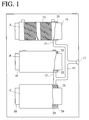
- the cavity A is smallest while the cavity C is largest.
- a common mandrel 10 may be inserted into each cavity A, B, C.
- a molten resin supplied through an inlet 11 of the die is injected into each cavity A, B, C through runners 12 and gates 13.
- a thin inner cylindrical member 21 is formed as shown in Figs. 1-3.
- the mandrel 10 formed with the inner cylindrical thermoplastic resin member 21 having a spiral groove 23 on an outer surface is discharged from the die.
- a heating resistance wire 22 is wound around the thin inner cylindrical thermoplastic resin member 21 in the groove 23.
- the heating resistance wire 22 may be coated with a thermoplastic resin.
- the heating resistance wire 22 is connected to pins 24, 24 fixed to the inner cylindrical member 21 at both ends.
- the injection-molded product 27 is discharged from the cavity B in a state in which the mandrel 10 is attached to the inner cylindrical member 21.
- the injection-molded product 27 is inserted into the cavity C, and a molten resin is injected into the cavity C to form a second outer cylindrical member 26 around the injection-molded product 27.
- the mandrel 10 is removed from the molded product to obtain the electric welding pipe joint 28 as shown in Figs. 2 and 3.
- the inner cylindrical member 21, the first outer cylindrical member 25 and the second outer cylindrical member 26 each made of a thermoplastic resin are fused integrally to each other by heat of the injected molten resin.
- a thin inner cylindrical member 21 for another joint may be formed in the cavity A, and an injection-molded product 27 for a further joint may be formed in the cavity B.
- a mandrel 10 is inserted into the cavity A, an inner cylindrical member 21 which is formed around the mandrel 10 in the cavity A and is provided with a heating resistance wire 21 in a groove 23 on an outer surface is inserted into the cavity B, and an injection-molded product 27 (formed in the cavity B) consisting of the mandrel 10, the inner cylindrical member 21 formed around the mandrel 10 and the first outer cylindrical member 25 integrally formed around the inner cylindrical member 21 is positioned in the cavity C simultaneously.
- a molten resin is charged into the die through an inlet 11 to carry out injection molding simultaneously in the cavities A, B and C.
- the injection time corresponds to the longest cooling time among the cavities A, B and C, the injection time can be reduced by decreasing the longest cooling time in the overall injection molding cycle.
- the inner cylindrical member 21 and the first outer cylindrical member 25 may be formed from a resin (natural) such as polyethylene, while the second outer cylindrical member 26 may be formed from a weather-proofed resin such as carbon black-containing polyethylene.
- the electric welding pipe joint shown in Figs. 2 and 3 differ from each other in a structure at both ends. Specifically, in the electric welding pipe joint shown in Fig. 2, the inner cylindrical member 21, the first outer cylindrical member 25 and the second outer cylindrical member 26 have the same length in the longitudinal direction, the first outer cylindrical member 25 being exposed at both ends. On the other hand, in the electric welding pipe joint shown in Fig. 3, the first outer cylindrical member 25 is shorter than the inner cylindrical member 21 and the second outer cylindrical member 26, both ends of the first outer cylindrical member 25 being covered by the second outer cylindrical member 26. In this structure, the second outer cylindrical member 26 is fused to both the inner cylindrical member 21 and the first outer cylindrical member 25, increasing the adhesion of these three thermoplastic resin layers.
- Fig. 4 shows the steps of producing a socket-type electric welding pipe joint having a nominal bore diameter of 150 mm (6 inches), an outer diameter of 207 mm and a length of 248 mm, whose outer cylindrical member 32 has a thickness of 22 mm, by a conventional method.
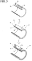
- Fig. 5 shows the steps of producing a socket-type electric welding pipe joint having a nominal bore diameter of 150 mm (6 inches), an outer diameter of 207 mm and a length of 248 mm, whose second outer cylindrical member 26 has a thickness of 11 mm, by the method of the present invention.
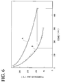
- Fig. 6 shows how fast the outer cylindrical member 32 and the second outer cylindrical member 26 are cooled in a die.
- Fig. 4 shows the steps of producing a socket-type electric welding pipe joint having a nominal bore diameter of 150 mm (6 inches), an outer diameter of 207 mm and a length of 248 mm, whose second outer cylindrical member 26 has a thickness of 11 mm, by the method of the present invention.
- A denotes the temperature change with time of the 22-mm-thick outer cylindrical member 32 in the conventional electric welding pipe joint
- B denotes the temperature change with time of the 11-mm-thick second outer cylindrical member 26 in the electric welding pipe joint of the present invention.
- Fig. 7 showing the relation between the injection molding time (cooling time) and the thickness of a resin layer at a temperature at which the electric welding pipe joint is discharged from the die.
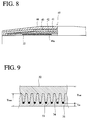
- the inner cylindrical member 31 has a smallest thickness T in 0.6 mm at a bottom of a spiral groove and a largest thickness T max of 5.5 mm in a spiral ridge as shown in Fig. 9, and the outer cylindrical member 32 formed around the inner cylindrical member 31 has a thickness T out of 22 mm.
- the cooling time of the inner cylindrical member 31 after injection molding is 90 seconds, and the cooling time of the outer cylindrical member 32 after injection molding is 360 seconds.
- the injection-molded pipe joint is discharged from the die at 135°C.
- the injection molding conditions of the outer cylindrical member 32 are plotted as a point E in Fig. 7.
- the inner cylindrical member 21 has the same size as that of the inner cylindrical member 31 of the above conventional electric welding pipe joint, and an outer cylindrical member (corresponding to the outer cylindrical member 32 of the conventional pipe joint) is constituted by an intermediate cylindrical member (first outer cylindrical member) 25 and a final outer cylindrical member (second outer cylindrical member) 26 each having a thickness of 11 mm, half of the thickness of the outer cylindrical member 32 of the above conventional electric welding pipe joint.
- the injection molding time is 100 seconds for each intermediate cylindrical member 25 and final outer cylindrical member 26.
- the injection-molded pipe joint is discharged from the die at 130°C. An electric welding pipe joint free from defects such as voids is thus obtained by this method.
- the injection molding conditions for the first and second outer cylindrical members 25, 26 are plotted as a point F in Fig. 7.
- the inner cylindrical member 31 has a smallest thickness T in of 0.8 mm at a bottom of a spiral groove and a largest thickness T max of 5.5 mm at a top of a spiral ridge, and the outer cylindrical member 32 formed around the inner cylindrical member 31 has a thickness T out of 28 mm.
- the cooling time of the inner cylindrical member 31 after injection molding is 100 seconds, and the cooling time of the outer cylindrical member 32 after injection molding is 900 seconds as shown by a point J in Fig. 7.
- the injection-molded pipe joint is discharged from the die at 120°C.
- the inner cylindrical member 21 has the same size as that of the inner cylindrical member 31 of the above conventional electric welding pipe joint, and an outer cylindrical member (corresponding to the outer cylindrical member 32) is constituted by an intermediate cylindrical member (first outer cylindrical member) 25 and a final outer cylindrical member (second outer cylindrical member) 26 each having a thickness of 14 mm, half of the thickness of the outer cylindrical member of the above conventional electric welding pipe joint.
- the injection molding time is 150 seconds for each of the intermediate cylindrical member 25 and the final outer cylindrical member 26 as shown by a point K in Fig. 7.
- the injection-molded pipe joint is discharged from the die at 115°C, lower than the temperature for the conventional electric welding pipe joint. An electric welding pipe joint free from defects such as voids is thus obtained by this method.
- Fig. 8 shows a socket-type electric welding pipe joint having a nominal bore diameter of 200 mm (8 inches) according to the third embodiment of the present invention which comprises an inner cylindrical member and an outer cylindrical member constituted by three layers to reduce the injection molding time.
- the inner cylindrical member 41 is wound with a heating resistance wire 22 in a spiral groove 41a on an outer surface, and first, second and third outer cylindrical members 42, 43 and 44 are injection-molded in this order around the outer surface of the inner cylindrical member 41 to form an integral electric welding pipe joint 45.
- Each of the first, second and third outer cylindrical members 42, 43 and 44 has a thickness of 9.5 mm, about one-third of the thickness (28 mm) of the outer cylindrical member 32 of the conventional electric welding pipe joint.
- both of the first outer cylindrical member 42 and the second outer cylindrical member 43 have grooves on their outer surfaces to increase their surface areas which are brought into contact with an inner surface of the die cavity, thereby increasing cooling efficiency of the injected thermoplastic resin, leading to reduction of cooling time. Further, since a contact area increases between adjacent injected resin layers, their adhesion strength increases.
- the time interval between the injection of a molten resin and the discharge of the injection-molded product which may be called "cooling time,” was 115 seconds for the first outer cylindrical member 42 whose cooling time is longest, and the discharge temperature was 100°C. Accordingly, the electric welding pipe joint comprising four cylindrical members enjoys an injection molding cycle drastically reduced from 900 seconds to 115 seconds at a lower discharge temperature.
- This four-layer pipe joint also has an injection molding cycle reduced by 35 seconds from 150 seconds to 115 seconds, comparing with the above three-layer pipe joint.
- the outer cylindrical member may be constituted by four or more thermoplastic resin layers depending on the shape and size of the electric welding pipe joint and the specification of a molding die. However, considering the shape of a joint and the easiness and time of forming each layer, the outer cylindrical member may preferably be constituted by two to four thermoplastic resin layers.
- the outer cylindrical member may be divided to three to five layers not only in a radial direction but also in a longitudinal direction.
- the injection molding die it is not restricted to the die having three cavities A, B and C as described above, and a plurality of dies each having one or more cavities may be used to form multi-layered outer cylindrical members successively or simultaneously.
- each thermoplastic resin layer constituting the outer cylindrical member is thin, the injection pressure of a molten resin may be low. Accordingly, it is possible to prevent the thin inner cylindrical thermoplastic resin member from melting at the time of injection molding of the outer cylindrical member, thereby avoiding the irregular displacement of a heating resistance wire in the joint. Thus, the short circuiting of the heating resistance wire can be prevented in the pipe-connecting operation. Further, since each layer of the outer cylindrical member is quickly cooled after the injection molding, it does not suffer from internal defects such as voids, and the injection molding operation can be completed in a short period of time.
- the electric welding pipe joint of the present invention can have a nominal bore diameter of 75 mm (3 inches) or more, particularly 100 mm (4 inches) or more.
- Such electric welding pipe joint preferably has an inner cylindrical member and an outer cylindrical member each constituted by two or more resin layers having a thickness of 15 mm or less, preferably 10 mm or less.
- a large injection pressure or a long injection time is not required to prevent voids, etc.
- a smaller injection molding machine can be used for the production of large-diameter pipe joint.
Landscapes
- Engineering & Computer Science (AREA)
- Mechanical Engineering (AREA)
- General Engineering & Computer Science (AREA)
- Manufacturing & Machinery (AREA)
- Injection Moulding Of Plastics Or The Like (AREA)
- Branch Pipes, Bends, And The Like (AREA)
- Lining Or Joining Of Plastics Or The Like (AREA)
Applications Claiming Priority (6)
| Application Number | Priority Date | Filing Date | Title |
|---|---|---|---|
| JP16925394 | 1994-07-21 | ||
| JP169253/94 | 1994-07-21 | ||
| JP16925394 | 1994-07-21 | ||
| JP7063783A JP2849349B2 (ja) | 1994-03-25 | 1995-03-23 | 電気融着継手とその製造方法及びその射出成形用金型 |
| JP63783/95 | 1995-03-23 | ||
| JP6378395 | 1995-03-23 |
Publications (3)
| Publication Number | Publication Date |
|---|---|
| EP0693652A2 true EP0693652A2 (de) | 1996-01-24 |
| EP0693652A3 EP0693652A3 (de) | 1996-10-23 |
| EP0693652B1 EP0693652B1 (de) | 2001-01-10 |
Family
ID=26404908
Family Applications (1)
| Application Number | Title | Priority Date | Filing Date |
|---|---|---|---|
| EP95111534A Expired - Lifetime EP0693652B1 (de) | 1994-07-21 | 1995-07-21 | Elektroschweissmuffe |
Country Status (3)
| Country | Link |
|---|---|
| US (1) | US5618065A (de) |
| EP (1) | EP0693652B1 (de) |
| DE (1) | DE69519833T2 (de) |
Cited By (5)
| Publication number | Priority date | Publication date | Assignee | Title |
|---|---|---|---|---|
| NL1009169C2 (nl) * | 1998-05-14 | 1999-11-16 | Polva Pipelife Bv | Lasmofverbinding voor hogedrukleiding. |
| WO2001006168A1 (en) * | 1999-07-16 | 2001-01-25 | Atofina Research | Reinforced electro-welding sleeve for plastic pipes |
| RU2272214C1 (ru) * | 2004-07-13 | 2006-03-20 | Олег Витальевич Шаклеин | Способ изготовления трубопровода |
| US11543064B2 (en) * | 2017-10-31 | 2023-01-03 | Trelleborg Sealing Solutions Germany Gmbh | Continuous fiber reinforced composite and metal electrofusion coupler |
| WO2025049175A1 (en) * | 2023-08-28 | 2025-03-06 | Jones Iii Robert David | Method and apparatus for bonding reinforced hdpe pipes |
Families Citing this family (25)
| Publication number | Priority date | Publication date | Assignee | Title |
|---|---|---|---|---|
| US5835679A (en) | 1994-12-29 | 1998-11-10 | Energy Converters, Inc. | Polymeric immersion heating element with skeletal support and optional heat transfer fins |
| US5690148A (en) * | 1996-06-21 | 1997-11-25 | Ziu; Christopher G. | Closure fitting and flexibility support assembly for double-containment piping systems |
| US5916468A (en) * | 1996-07-08 | 1999-06-29 | Hitachi Metals Ltd. | Electrically weldable pipe joint and production method thereof |
| US6263158B1 (en) | 1999-05-11 | 2001-07-17 | Watlow Polymer Technologies | Fibrous supported polymer encapsulated electrical component |
| US6392208B1 (en) * | 1999-08-06 | 2002-05-21 | Watlow Polymer Technologies | Electrofusing of thermoplastic heating elements and elements made thereby |
| AU780812B2 (en) * | 1999-09-14 | 2005-04-21 | Georg Fischer Wavin Ag | Improved welding socket |
| US6392206B1 (en) | 2000-04-07 | 2002-05-21 | Waltow Polymer Technologies | Modular heat exchanger |
| US6433317B1 (en) | 2000-04-07 | 2002-08-13 | Watlow Polymer Technologies | Molded assembly with heating element captured therein |
| US6519835B1 (en) | 2000-08-18 | 2003-02-18 | Watlow Polymer Technologies | Method of formable thermoplastic laminate heated element assembly |
| US20020058122A1 (en) * | 2000-11-06 | 2002-05-16 | Tsuyoshi Arai | Insert molded product |
| US6539171B2 (en) | 2001-01-08 | 2003-03-25 | Watlow Polymer Technologies | Flexible spirally shaped heating element |
| US6719018B2 (en) | 2001-05-08 | 2004-04-13 | Henry Colombo | Underground beverage conduit system |
| JP2005151676A (ja) * | 2003-11-14 | 2005-06-09 | Mitsubishi Fuso Truck & Bus Corp | センサハーネスの固定構造 |
| GB2421469B (en) * | 2004-12-23 | 2010-03-03 | Uponor Innovation Ab | Plastic pipe |
| GB2425337A (en) * | 2005-04-22 | 2006-10-25 | Uponor Innovation Ab | Electrofusion fitting to seal barrier layer of composite pipe |
| JP2009536222A (ja) * | 2006-05-05 | 2009-10-08 | アイシス ファーマシューティカルズ, インコーポレーテッド | Pcsk9の発現を調節するための化合物および方法 |
| ITMI20062503A1 (it) * | 2006-12-22 | 2008-06-23 | Geco System Spa | Metodo e assieme per riparare giuntare o irrobustire tubi in materiale plastico |
| WO2012177758A1 (en) * | 2011-06-21 | 2012-12-27 | United Pipeline Systems, Inc. | Connections of lined pipe |
| JP5812486B2 (ja) * | 2011-10-06 | 2015-11-11 | 国立研究開発法人海洋研究開発機構 | 溶断装置 |
| EP2780159B1 (de) | 2011-11-16 | 2019-01-09 | Shawcor Ltd. | Flexibles, verstärktes rohr und verstärkungsband dafür |
| WO2013071448A1 (en) * | 2011-11-16 | 2013-05-23 | Flexpipe Systems Inc. | Connection for a thermoplastic pipe, assembly and method |
| AT516393B1 (de) | 2015-03-18 | 2016-05-15 | Agru Kunststofftechnik Ges M B H | Induktionsverbindungsmuffe |
| EP3434454B1 (de) * | 2017-07-26 | 2023-03-01 | Georg Fischer Wavin AG | Elastische elektroschweissverbindung |
| CN107588268B (zh) * | 2017-11-08 | 2019-05-03 | 宁波市宇华电器有限公司 | 一种双层电熔管件 |
| US11725755B2 (en) | 2020-10-29 | 2023-08-15 | United Pipeline Systems, Inc. | Connections of lined pipe |
Citations (1)
| Publication number | Priority date | Publication date | Assignee | Title |
|---|---|---|---|---|
| JPS5769010A (en) | 1980-08-29 | 1982-04-27 | Sturm Werner | Thermoplastic welded sleeve and assembled body of mold for manufacture of said sleeve |
Family Cites Families (17)
| Publication number | Priority date | Publication date | Assignee | Title |
|---|---|---|---|---|
| CH622870A5 (de) * | 1977-06-03 | 1981-04-30 | Werner Sturm | |
| SU1393983A1 (ru) * | 1986-08-08 | 1988-05-07 | Предприятие П/Я Р-6594 | Способ изготовлени муфты из термопласта |
| GB2194749A (en) * | 1986-09-09 | 1988-03-16 | Du Pont | Method of manufacturing heat-weldable thermoplastic fittings |
| US4784285A (en) * | 1987-08-03 | 1988-11-15 | Chemcast Corporation | Dual durometer self locking and sealing plugs and method for making same |
| US5150922A (en) * | 1989-01-11 | 1992-09-29 | Osaka Gas Co., Ltd. | Electrofusion joint and hot water supply header using the same |
| GB8910070D0 (en) * | 1989-05-03 | 1989-06-21 | Fusion Plastics Ltd | Electro-fusion fittings |
| JP2875021B2 (ja) * | 1989-08-14 | 1999-03-24 | オーリー ソーレンセン,ジェンス | 逐次射出する多成分射出成形法 |
| SU1737216A1 (ru) * | 1989-09-12 | 1992-05-30 | Уральский Филиал Центрального Научно-Исследовательского Института Материаловедения | Способ соединени труб с внутренней облицовкой |
| JPH03129195A (ja) * | 1989-10-13 | 1991-06-03 | Sumitomo Metal Ind Ltd | プラスチック管用継手およびプラスチック管の接合方法 |
| US5125690A (en) * | 1989-12-15 | 1992-06-30 | Metcal, Inc. | Pipe joining system and method |
| FR2664531A1 (fr) * | 1990-07-11 | 1992-01-17 | Brun Pierre | Piece multi-matiere, et son procede d'obtention. |
| DE9103254U1 (de) * | 1991-03-16 | 1992-07-16 | KHS ETI-TEC Maschinenbau GmbH, 4006 Erkrath | Flaschendrehteller |
| EP0535247B1 (de) * | 1991-04-19 | 1997-07-09 | Sekisui Kagaku Kogyo Kabushiki Kaisha | Kupplung für rohrleitungen |
| CH683026A5 (de) * | 1991-06-18 | 1993-12-31 | Gunzenhauser Ag J & R | Schweissmuffe für Kunststoffrohre. |
| DE4203626C2 (de) * | 1992-02-08 | 1993-11-04 | Fischer Georg Rohrleitung | Schweissmuffe und verfahren zu deren herstellung |
| JPH0627796A (ja) * | 1992-07-08 | 1994-02-04 | Konica Corp | 現像器 |
| EP0612953A1 (de) * | 1993-02-22 | 1994-08-31 | Streng Plastic AG | Verbindung rohrförmiger Kunststoffteile |
-
1995
- 1995-07-20 US US08/504,866 patent/US5618065A/en not_active Expired - Lifetime
- 1995-07-21 DE DE69519833T patent/DE69519833T2/de not_active Expired - Fee Related
- 1995-07-21 EP EP95111534A patent/EP0693652B1/de not_active Expired - Lifetime
Patent Citations (1)
| Publication number | Priority date | Publication date | Assignee | Title |
|---|---|---|---|---|
| JPS5769010A (en) | 1980-08-29 | 1982-04-27 | Sturm Werner | Thermoplastic welded sleeve and assembled body of mold for manufacture of said sleeve |
Cited By (9)
| Publication number | Priority date | Publication date | Assignee | Title |
|---|---|---|---|---|
| NL1009169C2 (nl) * | 1998-05-14 | 1999-11-16 | Polva Pipelife Bv | Lasmofverbinding voor hogedrukleiding. |
| WO1999058894A1 (en) | 1998-05-14 | 1999-11-18 | Pipelife Nederland B.V. | Coupling sleeve for high-pressure pipe |
| US6478338B1 (en) | 1998-05-14 | 2002-11-12 | Pipelife Nederland B.V. | Coupling sleeve for high-pressure pipe |
| AU759659B2 (en) * | 1998-05-14 | 2003-04-17 | Pipelife Nederland B.V. | Coupling sleeve for high-pressure pipe |
| WO2001006168A1 (en) * | 1999-07-16 | 2001-01-25 | Atofina Research | Reinforced electro-welding sleeve for plastic pipes |
| US6406063B1 (en) | 1999-07-16 | 2002-06-18 | Fina Research, S.A. | Pipe fittings |
| RU2272214C1 (ru) * | 2004-07-13 | 2006-03-20 | Олег Витальевич Шаклеин | Способ изготовления трубопровода |
| US11543064B2 (en) * | 2017-10-31 | 2023-01-03 | Trelleborg Sealing Solutions Germany Gmbh | Continuous fiber reinforced composite and metal electrofusion coupler |
| WO2025049175A1 (en) * | 2023-08-28 | 2025-03-06 | Jones Iii Robert David | Method and apparatus for bonding reinforced hdpe pipes |
Also Published As
| Publication number | Publication date |
|---|---|
| US5618065A (en) | 1997-04-08 |
| DE69519833T2 (de) | 2001-08-02 |
| EP0693652A3 (de) | 1996-10-23 |
| DE69519833D1 (de) | 2001-02-15 |
| EP0693652B1 (de) | 2001-01-10 |
Similar Documents
| Publication | Publication Date | Title |
|---|---|---|
| EP0693652A2 (de) | Elektroschweissmuffe | |
| EP0396273B1 (de) | Elektroschweissmuffen | |
| US5228186A (en) | Method of manufacturing electro-fusion fittings | |
| JP2729900B2 (ja) | 中空体製品の成形方法および成形用金型 | |
| US6547551B2 (en) | Multilayer crosshead | |
| JP2849349B2 (ja) | 電気融着継手とその製造方法及びその射出成形用金型 | |
| JPH10315266A (ja) | 樹脂成形中空体 | |
| JPH08296785A (ja) | 電気融着継手及びその製造方法 | |
| JPH09207224A (ja) | 電気融着式管継手およびその製造方法 | |
| JP2939032B2 (ja) | 電気融着式プラスチック管継手の製造方法 | |
| JPH0968295A (ja) | 電気融着継手の製造方法 | |
| JP2001047464A (ja) | 電気融着継手の製造方法 | |
| JP4204960B2 (ja) | 射出成形金型と射出成形方法 | |
| JPH1038175A (ja) | 電気融着式管継手およびその製造方法 | |
| JPH09277313A (ja) | 筒状成形品用金型とその成形方法 | |
| JPH08244065A (ja) | 電気融着継手の製造方法 | |
| JPH0811155A (ja) | 中空成形品の成形方法 | |
| JPH1034719A (ja) | 電気融着式管継手の製造方法 | |
| JPH05256392A (ja) | 電気融着式プラスチック管継手 | |
| JPH0780933A (ja) | フランジ付樹脂ライニング鋼管の製造方法 | |
| JPS59143627A (ja) | 樹脂製油圧シリンダの製造方法 | |
| KR200213965Y1 (ko) | 나선형 중공관 제조장치 | |
| JPH1016000A (ja) | 電気融着継手の製造方法 | |
| JPH08219358A (ja) | 電気融着継手の製造方法 | |
| JPH07100890A (ja) | 樹脂射出成形品の製造方法および製造装置 |
Legal Events
| Date | Code | Title | Description |
|---|---|---|---|
| PUAI | Public reference made under article 153(3) epc to a published international application that has entered the european phase |
Free format text: ORIGINAL CODE: 0009012 |
|
| AK | Designated contracting states |
Kind code of ref document: A2 Designated state(s): CH DE GB LI MC |
|
| PUAL | Search report despatched |
Free format text: ORIGINAL CODE: 0009013 |
|
| AK | Designated contracting states |
Kind code of ref document: A3 Designated state(s): CH DE GB LI MC |
|
| 17P | Request for examination filed |
Effective date: 19960930 |
|
| 17Q | First examination report despatched |
Effective date: 19990127 |
|
| GRAG | Despatch of communication of intention to grant |
Free format text: ORIGINAL CODE: EPIDOS AGRA |
|
| GRAG | Despatch of communication of intention to grant |
Free format text: ORIGINAL CODE: EPIDOS AGRA |
|
| GRAH | Despatch of communication of intention to grant a patent |
Free format text: ORIGINAL CODE: EPIDOS IGRA |
|
| GRAH | Despatch of communication of intention to grant a patent |
Free format text: ORIGINAL CODE: EPIDOS IGRA |
|
| GRAA | (expected) grant |
Free format text: ORIGINAL CODE: 0009210 |
|
| AK | Designated contracting states |
Kind code of ref document: B1 Designated state(s): CH DE GB LI MC |
|
| REG | Reference to a national code |
Ref country code: CH Ref legal event code: EP |
|
| REF | Corresponds to: |
Ref document number: 69519833 Country of ref document: DE Date of ref document: 20010215 |
|
| REG | Reference to a national code |
Ref country code: CH Ref legal event code: NV Representative=s name: MICHELI & CIE INGENIEURS-CONSEILS |
|
| EN | Fr: translation not filed | ||
| PLBE | No opposition filed within time limit |
Free format text: ORIGINAL CODE: 0009261 |
|
| STAA | Information on the status of an ep patent application or granted ep patent |
Free format text: STATUS: NO OPPOSITION FILED WITHIN TIME LIMIT |
|
| REG | Reference to a national code |
Ref country code: GB Ref legal event code: IF02 |
|
| 26N | No opposition filed | ||
| PGFP | Annual fee paid to national office [announced via postgrant information from national office to epo] |
Ref country code: DE Payment date: 20080724 Year of fee payment: 14 Ref country code: CH Payment date: 20080815 Year of fee payment: 14 |
|
| PGFP | Annual fee paid to national office [announced via postgrant information from national office to epo] |
Ref country code: MC Payment date: 20080721 Year of fee payment: 14 |
|
| PGFP | Annual fee paid to national office [announced via postgrant information from national office to epo] |
Ref country code: GB Payment date: 20080723 Year of fee payment: 14 |
|
| PG25 | Lapsed in a contracting state [announced via postgrant information from national office to epo] |
Ref country code: MC Free format text: LAPSE BECAUSE OF NON-PAYMENT OF DUE FEES Effective date: 20090731 |
|
| REG | Reference to a national code |
Ref country code: CH Ref legal event code: PL |
|
| GBPC | Gb: european patent ceased through non-payment of renewal fee |
Effective date: 20090721 |
|
| PG25 | Lapsed in a contracting state [announced via postgrant information from national office to epo] |
Ref country code: LI Free format text: LAPSE BECAUSE OF NON-PAYMENT OF DUE FEES Effective date: 20090731 Ref country code: CH Free format text: LAPSE BECAUSE OF NON-PAYMENT OF DUE FEES Effective date: 20090731 |
|
| PG25 | Lapsed in a contracting state [announced via postgrant information from national office to epo] |
Ref country code: GB Free format text: LAPSE BECAUSE OF NON-PAYMENT OF DUE FEES Effective date: 20090721 |
|
| PG25 | Lapsed in a contracting state [announced via postgrant information from national office to epo] |
Ref country code: DE Free format text: LAPSE BECAUSE OF NON-PAYMENT OF DUE FEES Effective date: 20100202 |