EP0694821B1 - Selbstpolarisierendes Übertragungselement - Google Patents
Selbstpolarisierendes Übertragungselement Download PDFInfo
- Publication number
- EP0694821B1 EP0694821B1 EP95305124A EP95305124A EP0694821B1 EP 0694821 B1 EP0694821 B1 EP 0694821B1 EP 95305124 A EP95305124 A EP 95305124A EP 95305124 A EP95305124 A EP 95305124A EP 0694821 B1 EP0694821 B1 EP 0694821B1
- Authority
- EP
- European Patent Office
- Prior art keywords
- transfer member
- layer
- piezoelectric
- roll
- piezoelectric material
- Prior art date
- Legal status (The legal status is an assumption and is not a legal conclusion. Google has not performed a legal analysis and makes no representation as to the accuracy of the status listed.)
- Expired - Lifetime
Links
- 238000012546 transfer Methods 0.000 title claims description 33
- 239000000463 material Substances 0.000 claims description 32
- 230000005684 electric field Effects 0.000 claims description 6
- 238000003384 imaging method Methods 0.000 claims description 5
- 230000010287 polarization Effects 0.000 claims description 4
- 229920006254 polymer film Polymers 0.000 claims description 4
- 239000010410 layer Substances 0.000 description 10
- 238000000034 method Methods 0.000 description 7
- 239000000843 powder Substances 0.000 description 6
- 239000002344 surface layer Substances 0.000 description 6
- 239000002033 PVDF binder Substances 0.000 description 4
- 229920002981 polyvinylidene fluoride Polymers 0.000 description 4
- 239000000758 substrate Substances 0.000 description 3
- 238000009472 formulation Methods 0.000 description 2
- 239000000203 mixture Substances 0.000 description 2
- 230000002093 peripheral effect Effects 0.000 description 2
- 241001354243 Corona Species 0.000 description 1
- 229920006370 Kynar Polymers 0.000 description 1
- 229920009405 Polyvinylidenefluoride (PVDF) Film Polymers 0.000 description 1
- 230000001154 acute effect Effects 0.000 description 1
- 238000013459 approach Methods 0.000 description 1
- 238000004140 cleaning Methods 0.000 description 1
- 238000005056 compaction Methods 0.000 description 1
- 230000000994 depressogenic effect Effects 0.000 description 1
- 238000013461 design Methods 0.000 description 1
- 238000011161 development Methods 0.000 description 1
- 230000005686 electrostatic field Effects 0.000 description 1
- 239000006261 foam material Substances 0.000 description 1
- 238000004519 manufacturing process Methods 0.000 description 1
- 238000006386 neutralization reaction Methods 0.000 description 1
- 239000002245 particle Substances 0.000 description 1
- 229920002635 polyurethane Polymers 0.000 description 1
- 239000004814 polyurethane Substances 0.000 description 1
- 230000001360 synchronised effect Effects 0.000 description 1
Images


Classifications
-
- G—PHYSICS
- G03—PHOTOGRAPHY; CINEMATOGRAPHY; ANALOGOUS TECHNIQUES USING WAVES OTHER THAN OPTICAL WAVES; ELECTROGRAPHY; HOLOGRAPHY
- G03G—ELECTROGRAPHY; ELECTROPHOTOGRAPHY; MAGNETOGRAPHY
- G03G15/00—Apparatus for electrographic processes using a charge pattern
- G03G15/14—Apparatus for electrographic processes using a charge pattern for transferring a pattern to a second base
- G03G15/16—Apparatus for electrographic processes using a charge pattern for transferring a pattern to a second base of a toner pattern, e.g. a powder pattern, e.g. magnetic transfer
- G03G15/1665—Apparatus for electrographic processes using a charge pattern for transferring a pattern to a second base of a toner pattern, e.g. a powder pattern, e.g. magnetic transfer by introducing the second base in the nip formed by the recording member and at least one transfer member, e.g. in combination with bias or heat
- G03G15/167—Apparatus for electrographic processes using a charge pattern for transferring a pattern to a second base of a toner pattern, e.g. a powder pattern, e.g. magnetic transfer by introducing the second base in the nip formed by the recording member and at least one transfer member, e.g. in combination with bias or heat at least one of the recording member or the transfer member being rotatable during the transfer
- G03G15/1685—Structure, details of the transfer member, e.g. chemical composition
-
- Y—GENERAL TAGGING OF NEW TECHNOLOGICAL DEVELOPMENTS; GENERAL TAGGING OF CROSS-SECTIONAL TECHNOLOGIES SPANNING OVER SEVERAL SECTIONS OF THE IPC; TECHNICAL SUBJECTS COVERED BY FORMER USPC CROSS-REFERENCE ART COLLECTIONS [XRACs] AND DIGESTS
- Y10—TECHNICAL SUBJECTS COVERED BY FORMER USPC
- Y10T—TECHNICAL SUBJECTS COVERED BY FORMER US CLASSIFICATION
- Y10T428/00—Stock material or miscellaneous articles
- Y10T428/13—Hollow or container type article [e.g., tube, vase, etc.]
- Y10T428/1352—Polymer or resin containing [i.e., natural or synthetic]
- Y10T428/1355—Elemental metal containing [e.g., substrate, foil, film, coating, etc.]
-
- Y—GENERAL TAGGING OF NEW TECHNOLOGICAL DEVELOPMENTS; GENERAL TAGGING OF CROSS-SECTIONAL TECHNOLOGIES SPANNING OVER SEVERAL SECTIONS OF THE IPC; TECHNICAL SUBJECTS COVERED BY FORMER USPC CROSS-REFERENCE ART COLLECTIONS [XRACs] AND DIGESTS
- Y10—TECHNICAL SUBJECTS COVERED BY FORMER USPC
- Y10T—TECHNICAL SUBJECTS COVERED BY FORMER US CLASSIFICATION
- Y10T428/00—Stock material or miscellaneous articles
- Y10T428/13—Hollow or container type article [e.g., tube, vase, etc.]
- Y10T428/1352—Polymer or resin containing [i.e., natural or synthetic]
- Y10T428/1376—Foam or porous material containing
-
- Y—GENERAL TAGGING OF NEW TECHNOLOGICAL DEVELOPMENTS; GENERAL TAGGING OF CROSS-SECTIONAL TECHNOLOGIES SPANNING OVER SEVERAL SECTIONS OF THE IPC; TECHNICAL SUBJECTS COVERED BY FORMER USPC CROSS-REFERENCE ART COLLECTIONS [XRACs] AND DIGESTS
- Y10—TECHNICAL SUBJECTS COVERED BY FORMER USPC
- Y10T—TECHNICAL SUBJECTS COVERED BY FORMER US CLASSIFICATION
- Y10T428/00—Stock material or miscellaneous articles
- Y10T428/13—Hollow or container type article [e.g., tube, vase, etc.]
- Y10T428/1352—Polymer or resin containing [i.e., natural or synthetic]
- Y10T428/139—Open-ended, self-supporting conduit, cylinder, or tube-type article
-
- Y—GENERAL TAGGING OF NEW TECHNOLOGICAL DEVELOPMENTS; GENERAL TAGGING OF CROSS-SECTIONAL TECHNOLOGIES SPANNING OVER SEVERAL SECTIONS OF THE IPC; TECHNICAL SUBJECTS COVERED BY FORMER USPC CROSS-REFERENCE ART COLLECTIONS [XRACs] AND DIGESTS
- Y10—TECHNICAL SUBJECTS COVERED BY FORMER USPC
- Y10T—TECHNICAL SUBJECTS COVERED BY FORMER US CLASSIFICATION
- Y10T428/00—Stock material or miscellaneous articles
- Y10T428/31504—Composite [nonstructural laminate]
- Y10T428/3154—Of fluorinated addition polymer from unsaturated monomers
-
- Y—GENERAL TAGGING OF NEW TECHNOLOGICAL DEVELOPMENTS; GENERAL TAGGING OF CROSS-SECTIONAL TECHNOLOGIES SPANNING OVER SEVERAL SECTIONS OF THE IPC; TECHNICAL SUBJECTS COVERED BY FORMER USPC CROSS-REFERENCE ART COLLECTIONS [XRACs] AND DIGESTS
- Y10—TECHNICAL SUBJECTS COVERED BY FORMER USPC
- Y10T—TECHNICAL SUBJECTS COVERED BY FORMER US CLASSIFICATION
- Y10T428/00—Stock material or miscellaneous articles
- Y10T428/31504—Composite [nonstructural laminate]
- Y10T428/31678—Of metal
Definitions
- the present invention relates generally to an apparatus for transfer of charged toner particles in an electrostatographic printing machine, and more particularly, concerns a transfer member for use in electrostatographic printers.
- US-A-4106933 to Taylor teaches a method for printing using photoconductor with piezoelectric material having dipoles that are permanently poled to form a permanent pattern corresponding to a graphic representation. Subsequently, the permanently poled material can be used by straining the material to produce a charge pattern representative of the graphic representation, which can then be developed with toner powder, transferred to a sheet of paper, and fused to form a printed page. The straining, toning and fusing process may be repeated, thereby producing multiple copies.
- An object of the present invention is to strive to meet the above need.
- the present invention provides a self-biasing transfer member for use in electrostatographic printers, comprises:
- a roll member comprising an interior layer of compressible material, and an exterior surface layer comprising piezoelectric material positioned about said exterior layer for generating an electric field in response to being deformed.
- an electrostatographic printer in accordance with the invention and an imaging support surface, wherein said transfer member is urged into contact with the imaging support surface to form a nip region therebetween; and wherein the compressible material is compressed by the support surface under said urging of the transfer member and said piezoelectric material is deformed thereby.
- a conformable, self biasing roll member 10 in accordance with the present invention is shown in the configuration of a transfer system of a typical electrostatographic printing machine.
- a drum-type photoconductive insulating surface 15 is shown in operative engagement with the self biasing roll 10, forming a nip 22 therebetween.
- a powder toner image 17 previously formed and developed in accordance with conventional electrostatographic copying processes is present on the surface of the photoconductive insulating drum.
- a copy sheet 16 or other support substrate travels through the nip 22 formed in the area of contact between the self biasing roll 10 and the photoconductive insulating surface 15 for receiving the powder toner image 17 from drum 15.
- the powder toner image is transferred to the support sheet 16, appearing as a transferred image 18 thereon.
- the physics involved in using a conformable roll for the transferring process in such an electrostatographic printing apparatus is well known in the industry.
- the transferred image 18 on the support sheet 16 may be subsequently processed, for example, by fusing the image onto the support sheet.
- the conformable roll 10 comprises a layer of compressible material 13 coated onto core 12.
- the roll member 10 is normally cylindrical with the layer 13 uniformly surrounding the central core 12 in a coaxial manner.
- the layer 13 may be comprised of a polyurethane formulation or any other material capable of providing desirable compressibility characteristics. This formulation may be closed cell or open cell, i.e., a foam material, which is sufficiently compressible.
- a peripheral surface layer 14 comprises a piezoelectric polymer film, such as polyvinylidene fluoride (PVDF) film, preferably Kynar® piezo film manufactured by Pennwalt KTM.
- PVDF polyvinylidene fluoride
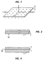
- Piezoelectric materials are formed by stretching PVDF film in one direction, and applying a large electric field to electrically polarize it in a direction perpendicular to the film. As shown in figure 1, the stretch direction is denoted by “T” and the polarization direction is denoted by “P”, or in the polar coordinates shown by “1” and “3” respectively. When a PVDF sheet is strained, it develops an internal electric field which is proportional to the deformation.
- the present invention utilizes either a bimorph or a unimorph structure referred to as a "Xeromorph".
- a bimorph Xeromorph consists of two PVDF sheets 6 laminated together with each sheet polarization direction opposed to each other having only a bottom electrode 7, as shown in Figure 2.
- An unimorph Xeromorph consists of a single PVDF sheet 6 laminated to a thick substrate 4 as shown in Figure 3.
- the substrate material may comprise materials which can be bent, and have no piezoelectric properties.
- Xeromorph surface layer 14 is sufficiently elastic and resilient to yield to the compressible characteristics of the conformable underlying layer 13.
- the conformable roll 10 is subjected to a compressive force in the nip 22 formed in the area of contact between the roll 10 and the photoconductive drum 15. As roll 10 is brought into much closer proximity to the photoconductive surface 15, upon which the powder toner image is located, the compressive force causes deformation of the piezoelectric layer such that an electric potential is generated on the surface of roll 10 in the nip region in order to induce transfer of the powder toner image to copy sheet 16.
- Conformable roll 10 is maintained in tension by a pair of springs (not shown) resiliently urging conformable roll 10 against drum with the desired spring force to deform conformable roll 10 to generate the desired electric potential.
- conformable roll surface 10 against drum 15
- neutralization and cleaning brush 30 cleans the surface of conformable roll 10 and eliminates residue charges thereon by being connected to ground, so that there is no electric field in the pre-nip region prior to deformation in the nip 22.
- Deformation of the peripheral surface layer 14 in the transfer nip 22 can be increased such that higher transfer fields can be applied to achieve high transfer efficiencies, if necessary.
- FIG. 5 Another embodiment of the present invention is illustrated in Figure 5.
- Conformable roll 10 is subjected to a compressive force applied by conductive blade 50.
- Blade 50 serves three functions: 1) deform Xeromorph surface layer to create a net charge and non-zero potential; 2) neutralize this non-zero surface potential by commutating this net charge to ground through the conductive blade; 3) clean debris from the surface of the Xeromorph surface layer.
- An advantageous feature of this specific embodiment is the independence from nip pressure to generate the desired electrical potential on the surface of the roll thereby eliminating the possibility of excess nip pressure which can result in hollow character images due to compaction of toner against the surface of the photoconductive member. It should be noted that sufficient nip pressure should be applied to minimize the transfer zone air gap.
- the roll member of the present invention is operated in a synchronous mode in which the roll rotates in the same direction as the photoconductive surface.
- the conformable roll member of the present invention can be operated in an asynchronous mode, in which the roll rotates in the opposite direction as the image receiver and the photoconductive surface.
- a self-biasing transfer member which is in the form of a roll member fully provides the advantages of the invention as described above. It is also evident to those of the ordinary skill in the art that the self-biasing transfer member could be in the form of an endless belt entrained over a pair of rollers, wherein, for example, one of the rollers performs the function of an incompressible material against which the conformable material of the endless belt is depressed to enable the piezoelectric material thereover to deform.
Landscapes
- Physics & Mathematics (AREA)
- General Physics & Mathematics (AREA)
- Electrostatic Charge, Transfer And Separation In Electrography (AREA)
Claims (9)
- Selbstvorspannendes Übertragungselement (10) zum Einsatz in elektrostatographischen Druckern, das umfaßt:eine Schicht aus zusammendrückbarem Material (13); undeine Schicht, die piezoelektrisches Material (14) umfaßt und auf der zusammendrückbaren Schicht angeordnet ist, wobei das piezoelektrische Material von dem Typ ist, der ein elektrisches Feld erzeugt, wenn er beim Zusammendrücken des zusammendrückbaren Materials (13) verformt wird.
- Übertragungselement nach Anspruch 1, wobei das Übertragungselement umfaßt:eine Walze (10), bei der das zusammendrückbare Material zylindrisch auf einem axial angeordneten Kern ausgebildet ist; undwobei die Walze um die Achse des Kerns herum gedreht werden kann.
- Übertragungselement nach Anspruch 1, wobei die Schicht aus zusammendrückbarem Material und die Schicht, die das piezoelektrische Material umfaßt, ein Endlosband bilden, und das Band um ein Paar Walzen herumläuft.
- Übertragungselement nach einem der vorangehenden Ansprüche, wobei das piezoelektrische Material eine Schicht aus piezoelektrischem Polymerfilm umfaßt.
- Übertragungselement nach einem der vorangehenden Ansprüche, wobei das piezoelektrische Material (14) umfaßt:eine erste Schicht aus piezoelektrischem Polymerfilm mit einer ersten Polarisierungsrichtung; undeine zweite Schicht aus piezoelektrischem Polymerfilm, die auf der ersten Schicht angeordnet ist und eine zweite Polarisationsrichtung entgegengesetzt zu der ersten Richtung hat.
- Elektrostatographischer Drucker, der ein Übertragungselement (10) gemäß einem der vorangehenden Ansprüche und eine Bildtragefläche (15) enthält, wobei das Übertragungselement (10) so mit der Bildtragefläche (15) in Kontakt gedrückt wird, daß ein Spaltbereich zwischen ihnen entsteht; undwobei das zusammendrückbare Material (13) durch den Druck auf das Übertragungselement (11) von der Tragefläche zusammengedrückt wird und das piezoelektrische Material (14) dadurch verformt wird.
- Elektrostatographischer Drucker nach Anspruch 6, wobei das Übertragungselement (10) durch Federn in die Bildtragefläche (15) hineingedrückt wird.
- Elektrostatographischer Drucker, der ein Übertragungselement (10) nach einem der Ansprüche 1 bis 5 und eine Klinge (50) enthält, wobei das Übertragungselement (10) durch die Klinge (50) verformt wird, die das zusammendrückbare Material (13) zusammendrückt.
- Elektrostatographischer Drucker nach Anspruch 6, 7 oder 8, wobei das Übertragungselement (10) mit einer Bürste (30) gereinigt wird, die gleichzeitig Restladungen auf der Oberfläche des piezoelektrischen Materials (14) auflöst.
Applications Claiming Priority (2)
| Application Number | Priority Date | Filing Date | Title |
|---|---|---|---|
| US08/282,588 US5520977A (en) | 1994-07-29 | 1994-07-29 | Self biasing transfer roll |
| US282588 | 1994-07-29 |
Publications (2)
| Publication Number | Publication Date |
|---|---|
| EP0694821A1 EP0694821A1 (de) | 1996-01-31 |
| EP0694821B1 true EP0694821B1 (de) | 1999-10-06 |
Family
ID=23082175
Family Applications (1)
| Application Number | Title | Priority Date | Filing Date |
|---|---|---|---|
| EP95305124A Expired - Lifetime EP0694821B1 (de) | 1994-07-29 | 1995-07-21 | Selbstpolarisierendes Übertragungselement |
Country Status (4)
| Country | Link |
|---|---|
| US (1) | US5520977A (de) |
| EP (1) | EP0694821B1 (de) |
| JP (1) | JPH0863008A (de) |
| DE (1) | DE69512583T2 (de) |
Families Citing this family (6)
| Publication number | Priority date | Publication date | Assignee | Title |
|---|---|---|---|---|
| US5671472A (en) * | 1996-06-24 | 1997-09-23 | Xerox Corporation | Xerographic systems using piezoelectric intermediate belt transfer |
| US5678145A (en) * | 1996-06-24 | 1997-10-14 | Xerox Corporation | Xerographic charging and transfer using the pyroelectric effect |
| US6085061A (en) * | 1998-12-22 | 2000-07-04 | Xerox Corporation | Active electrostatic cleaning brush |
| US6361483B1 (en) * | 1999-10-22 | 2002-03-26 | Morrison Berkshire, Inc. | System for controlling vibration of a dynamic surface |
| US6939279B2 (en) * | 2001-05-01 | 2005-09-06 | Ten Cate Enbi | Tire for skew reducing roller |
| CN104698688B (zh) * | 2015-04-03 | 2017-08-01 | 合肥京东方光电科技有限公司 | 摩擦辊及其使用方法 |
Family Cites Families (5)
| Publication number | Priority date | Publication date | Assignee | Title |
|---|---|---|---|---|
| US4106933A (en) | 1975-06-18 | 1978-08-15 | Minnesota Mining And Manufacturing Company | Piezoelectric method and medium for producing electrostatic charge patterns |
| SU699590A1 (ru) * | 1977-11-24 | 1979-11-25 | Киевский Ордена Ленина Политехнический Институт Им. 50-Летия Великой Октябрьской Социалистической Революции | Генератор посто нного тока |
| US5168313A (en) * | 1988-04-28 | 1992-12-01 | Kabushiki Kaisha Toshiba | Toner image transfer method and device for electrophotographic printing apparatus |
| US5065194A (en) * | 1990-05-29 | 1991-11-12 | Eastman Kodak Company | Piezo film cleaner |
| JP3086037B2 (ja) * | 1990-12-11 | 2000-09-11 | ゼロックス コーポレイション | 像形成装置及び像形成用シート |
-
1994
- 1994-07-29 US US08/282,588 patent/US5520977A/en not_active Expired - Fee Related
-
1995
- 1995-07-21 DE DE69512583T patent/DE69512583T2/de not_active Expired - Fee Related
- 1995-07-21 JP JP7185601A patent/JPH0863008A/ja not_active Withdrawn
- 1995-07-21 EP EP95305124A patent/EP0694821B1/de not_active Expired - Lifetime
Also Published As
| Publication number | Publication date |
|---|---|
| US5520977A (en) | 1996-05-28 |
| JPH0863008A (ja) | 1996-03-08 |
| EP0694821A1 (de) | 1996-01-31 |
| DE69512583T2 (de) | 2000-05-04 |
| DE69512583D1 (de) | 1999-11-11 |
Similar Documents
| Publication | Publication Date | Title |
|---|---|---|
| US3847478A (en) | Segmented bias roll | |
| EP0708385B1 (de) | Bilderzeugungsgerät | |
| EP0367157B1 (de) | Übertragungsvorrichtung und Bilderzeugungsgerät in einem | |
| US5185619A (en) | Electrostatic printing method and apparatus employing a pyroelectric imaging member | |
| EP0510963B1 (de) | Verfahren und Gerät zum Drucken | |
| EP0694821B1 (de) | Selbstpolarisierendes Übertragungselement | |
| EP0816941B1 (de) | Xerographische Systeme mit Bandzwischenübertragung | |
| US6016418A (en) | Image forming apparatus | |
| US5593151A (en) | Self biasing electrostatic paper transport | |
| EP0695975B1 (de) | Aufladeeinheit mit Selbstvorspannung | |
| US6144834A (en) | Self biasing, extended nip electrostatic cleaner | |
| US5929886A (en) | Ferroelectric polymer charge transfer imaging process | |
| US5678145A (en) | Xerographic charging and transfer using the pyroelectric effect | |
| US5668439A (en) | High voltage power supply | |
| US6006057A (en) | Piezoelectric imaging process | |
| JPH11249459A (ja) | 画像形成装置 | |
| JP4175714B2 (ja) | 中間転写体及び画像形成装置 | |
| JP2002182506A (ja) | 低荷重定着部材及び定着装置 | |
| JPH1145010A (ja) | 画像形成装置 | |
| JPH04318578A (ja) | 転写装置 | |
| JPH05232823A (ja) | 画像形成装置 | |
| JPH07287458A (ja) | 画像形成装置 | |
| JP2002099156A (ja) | 画像形成装置 | |
| JP2004226919A (ja) | 転写ベルトを用いた転写方法 | |
| JPH09218593A (ja) | 画像形成装置 |
Legal Events
| Date | Code | Title | Description |
|---|---|---|---|
| PUAI | Public reference made under article 153(3) epc to a published international application that has entered the european phase |
Free format text: ORIGINAL CODE: 0009012 |
|
| AK | Designated contracting states |
Kind code of ref document: A1 Designated state(s): DE FR GB |
|
| 17P | Request for examination filed |
Effective date: 19960731 |
|
| 17Q | First examination report despatched |
Effective date: 19980605 |
|
| GRAG | Despatch of communication of intention to grant |
Free format text: ORIGINAL CODE: EPIDOS AGRA |
|
| GRAG | Despatch of communication of intention to grant |
Free format text: ORIGINAL CODE: EPIDOS AGRA |
|
| GRAH | Despatch of communication of intention to grant a patent |
Free format text: ORIGINAL CODE: EPIDOS IGRA |
|
| GRAH | Despatch of communication of intention to grant a patent |
Free format text: ORIGINAL CODE: EPIDOS IGRA |
|
| GRAA | (expected) grant |
Free format text: ORIGINAL CODE: 0009210 |
|
| AK | Designated contracting states |
Kind code of ref document: B1 Designated state(s): DE FR GB |
|
| REF | Corresponds to: |
Ref document number: 69512583 Country of ref document: DE Date of ref document: 19991111 |
|
| ET | Fr: translation filed | ||
| PLBE | No opposition filed within time limit |
Free format text: ORIGINAL CODE: 0009261 |
|
| STAA | Information on the status of an ep patent application or granted ep patent |
Free format text: STATUS: NO OPPOSITION FILED WITHIN TIME LIMIT |
|
| 26N | No opposition filed | ||
| REG | Reference to a national code |
Ref country code: GB Ref legal event code: IF02 |
|
| PGFP | Annual fee paid to national office [announced via postgrant information from national office to epo] |
Ref country code: FR Payment date: 20020709 Year of fee payment: 8 |
|
| PGFP | Annual fee paid to national office [announced via postgrant information from national office to epo] |
Ref country code: GB Payment date: 20020717 Year of fee payment: 8 |
|
| PGFP | Annual fee paid to national office [announced via postgrant information from national office to epo] |
Ref country code: DE Payment date: 20020724 Year of fee payment: 8 |
|
| PG25 | Lapsed in a contracting state [announced via postgrant information from national office to epo] |
Ref country code: GB Free format text: LAPSE BECAUSE OF NON-PAYMENT OF DUE FEES Effective date: 20030721 |
|
| PG25 | Lapsed in a contracting state [announced via postgrant information from national office to epo] |
Ref country code: DE Free format text: LAPSE BECAUSE OF NON-PAYMENT OF DUE FEES Effective date: 20040203 |
|
| GBPC | Gb: european patent ceased through non-payment of renewal fee |
Effective date: 20030721 |
|
| PG25 | Lapsed in a contracting state [announced via postgrant information from national office to epo] |
Ref country code: FR Free format text: LAPSE BECAUSE OF NON-PAYMENT OF DUE FEES Effective date: 20040331 |
|
| REG | Reference to a national code |
Ref country code: FR Ref legal event code: ST |