EP0696823A1 - Wasserstoffabsorbierende elektrode und deren herstellung - Google Patents
Wasserstoffabsorbierende elektrode und deren herstellung Download PDFInfo
- Publication number
- EP0696823A1 EP0696823A1 EP95909963A EP95909963A EP0696823A1 EP 0696823 A1 EP0696823 A1 EP 0696823A1 EP 95909963 A EP95909963 A EP 95909963A EP 95909963 A EP95909963 A EP 95909963A EP 0696823 A1 EP0696823 A1 EP 0696823A1
- Authority
- EP
- European Patent Office
- Prior art keywords
- hydrogen absorbing
- acid
- electrode
- absorbing electrode
- alloy
- Prior art date
- Legal status (The legal status is an assumption and is not a legal conclusion. Google has not performed a legal analysis and makes no representation as to the accuracy of the status listed.)
- Granted
Links
Images


Classifications
-
- H—ELECTRICITY
- H01—ELECTRIC ELEMENTS
- H01M—PROCESSES OR MEANS, e.g. BATTERIES, FOR THE DIRECT CONVERSION OF CHEMICAL ENERGY INTO ELECTRICAL ENERGY
- H01M4/00—Electrodes
- H01M4/02—Electrodes composed of, or comprising, active material
- H01M4/36—Selection of substances as active materials, active masses, active liquids
- H01M4/38—Selection of substances as active materials, active masses, active liquids of elements or alloys
- H01M4/383—Hydrogen absorbing alloys
-
- B—PERFORMING OPERATIONS; TRANSPORTING
- B22—CASTING; POWDER METALLURGY
- B22F—WORKING METALLIC POWDER; MANUFACTURE OF ARTICLES FROM METALLIC POWDER; MAKING METALLIC POWDER; APPARATUS OR DEVICES SPECIALLY ADAPTED FOR METALLIC POWDER
- B22F1/00—Metallic powder; Treatment of metallic powder, e.g. to facilitate working or to improve properties
- B22F1/14—Treatment of metallic powder
- B22F1/145—Chemical treatment, e.g. passivation or decarburisation
-
- Y—GENERAL TAGGING OF NEW TECHNOLOGICAL DEVELOPMENTS; GENERAL TAGGING OF CROSS-SECTIONAL TECHNOLOGIES SPANNING OVER SEVERAL SECTIONS OF THE IPC; TECHNICAL SUBJECTS COVERED BY FORMER USPC CROSS-REFERENCE ART COLLECTIONS [XRACs] AND DIGESTS
- Y02—TECHNOLOGIES OR APPLICATIONS FOR MITIGATION OR ADAPTATION AGAINST CLIMATE CHANGE
- Y02E—REDUCTION OF GREENHOUSE GAS [GHG] EMISSIONS, RELATED TO ENERGY GENERATION, TRANSMISSION OR DISTRIBUTION
- Y02E60/00—Enabling technologies; Technologies with a potential or indirect contribution to GHG emissions mitigation
- Y02E60/10—Energy storage using batteries
-
- Y—GENERAL TAGGING OF NEW TECHNOLOGICAL DEVELOPMENTS; GENERAL TAGGING OF CROSS-SECTIONAL TECHNOLOGIES SPANNING OVER SEVERAL SECTIONS OF THE IPC; TECHNICAL SUBJECTS COVERED BY FORMER USPC CROSS-REFERENCE ART COLLECTIONS [XRACs] AND DIGESTS
- Y10—TECHNICAL SUBJECTS COVERED BY FORMER USPC
- Y10S—TECHNICAL SUBJECTS COVERED BY FORMER USPC CROSS-REFERENCE ART COLLECTIONS [XRACs] AND DIGESTS
- Y10S420/00—Alloys or metallic compositions
- Y10S420/90—Hydrogen storage
-
- Y—GENERAL TAGGING OF NEW TECHNOLOGICAL DEVELOPMENTS; GENERAL TAGGING OF CROSS-SECTIONAL TECHNOLOGIES SPANNING OVER SEVERAL SECTIONS OF THE IPC; TECHNICAL SUBJECTS COVERED BY FORMER USPC CROSS-REFERENCE ART COLLECTIONS [XRACs] AND DIGESTS
- Y10—TECHNICAL SUBJECTS COVERED BY FORMER USPC
- Y10T—TECHNICAL SUBJECTS COVERED BY FORMER US CLASSIFICATION
- Y10T29/00—Metal working
- Y10T29/49—Method of mechanical manufacture
- Y10T29/49002—Electrical device making
- Y10T29/49108—Electric battery cell making
- Y10T29/49115—Electric battery cell making including coating or impregnating
Definitions
- This invention relates to a hydrogen absorbing electrode using a hydrogen absorbing alloy and its manufacturing method.
- a nickel-hydride secondary battery using a hydrogen absorbing alloy, which can absorb and release hydrogen in a reversible manner, as an anode material has such features as low-pollution and high-energy density etc., so that it has been frequently used for power sources for portable equipment and electric motor etc., in place of a nickel-cadmium secondary battery and many studies and developments have been made thereon.
- the activation means that the oxide film is destroyed to acquire an aimed discharge capacity by carrying out several cycles of charge/discharge at the initial stage of charge/discharge.
- a discharge voltage and a battery capacity lower.
- a capacity balance between anode and cathode is lost at the initial stage of charge/discharge, an inside pressure rise etc. occurs and a cycle life is reduced.
- a method for carrying out an electrode making-up process under an inert gas atmosphere and (ii) a method for putting an oxide film removal process in the electrode making-up process etc. are proposed. In these proposed methods, however, there have been such problems as a complex equipment and a troublesome work etc. In addition, even in the electrode prepared by the above proposed methods, there has been such a problem as the formation of oxide film depending on storage conditions after making-up.
- the hydrogen absorbing alloy particles or hydrogen absorbing electrode is to be subjected to high-temperature alkaline treatment and (2) the hydrogen absorbing alloy particle is to be subjected to Ni-nonelectrolytic plating treatment.
- insulating needle-like rare earth hydroxide is produced on the alloy surface in the treatment (1), it is necessary to carry out an ultra-sonic cleaning for removing the hydroxide. Further, a considerable rinsing work is required in order to remove alkali completely. Therefore, the treatment has been troublesome. The existence of needle-like rare earth hydroxide will cause a decrease in conductivity and a shortening of battery life.
- An object of this invention is to provide a hydrogen absorbing electrode which does not require activation and a conductivity of which is not worsen even when it is used in alkaline electrolyte, and another object of it is to provide a method for manufacturing such a hydrogen absorbing electrode by a simple process only.
- a hydrogen absorbing electrode of this invention which uses a hydrogen absorbing alloy including at least one or more kinds of transition metals belonging to VIIa-group, VIII-group or Ib-group in periodic table at a specified percentage, is characterized in that a surface part of the hydrogen absorbing alloy forms a rich layer including the foregoing transition metals at a percentage larger than the foregoing specified percentage.
- the battery using the hydrogen electrode having the above structure has a high discharge voltage and battery capacity.
- the capacity balance between anode and cathode at the initial stage of charge/discharge is maintained and the inside pressure rise does not occur so that its service life is prolonged.
- electrode reaction is promoted with a good efficiency from the first cycle because the rich layer itself functions as a charge transfer reaction field.
- the rich layer is formed mainly by elusion of rare earth element, the needle-like rare earth hydroxide is not formed on the alloy surface so that the reduction of conductivity is controlled, even when the hydrogen absorbing electrode having the above structure is used as the anode in the alkaline electrolyte. Also from this point, the battery using the hydrogen absorbing electrode having the above structure becomes to have a high-capacity and a long service life.
- the hydrogen absorbing alloy has Mm (misch metal), Al and transition metals as its components.
- Mm is a composite of rare earth elements. La, Ce, Pr and Nd etc. may be mentioned as the rare earth elements.
- Elements belonging to VIIa-group, VIII-group and Ib-group in periodic table may be mainly mentioned as the transition metals. For example, Ni, Co, Mn, Fe and Cu etc. may be mentioned as these metals.
- the following structures may be used.
- a manufacturing method of hydrogen absorbing electrode of this invention which uses a hydrogen absorbing alloy including at least one or more kinds of transition metals belonging to VIIa-group, VIII-group or Ib-group in periodic table, is characterized in that acid treatment process is provided wherein particles of the hydrogen absorbing alloy are dipped in aqueous solution of pH2 through pH6, and then rinsed and dried.
- the oxide film formed on the alloy surface is removed and Al and rare earth elements etc. are eluded from the alloy surface, so that the surface part of the alloy becomes a rich layer having a larger inclusion percentage of transition metal than original one.
- the solution has an acidity stronger than pH2
- even the Ni forming a major component of the alloy will be corroded to cause a decrease in mass of the alloy and a deterioration of the electrode property.
- a thickness of the rich layer becomes hard to be controlled and a thick rich layer is formed so that the rich layer will be peeled off as the cycle progresses.
- the solution has an acidity weaker than pH6, the removal of oxide film and the elusion of Al and rare earth elements are hard to occur, so that the rich layer is hard to be formed. Since Al corrosive region is included in a range of pH2 to pH6, Al is ready to be eluded and the rich layer is apt to be formed. Since aqueous solution having an acidity of pH2 through pH6 is easily rinsed as compared with alkaline, the rinsing work is done within a short time so as to simplify the treatment.
- Fig. 1 is a partial sectional view of a hydrogen absorbing alloy after undergoing acid treatment of example 1.
- Fig. 2 is a view showing alloy composition ratio of a part corresponding to that of Fig. 1.
- Fig. 3 is a view showing a pore diameter distribution of a hydrogen absorbing alloy after undergoing acid treatment of example 1.
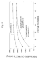
- Fig. 4 is a view showing cycle test results on a battery using a hydrogen absorbing electrode of example 1 and a battery using a hydrogen absorbing electrode of comparison example 1.
- Fig. 5 is a view showing a discharge curve of the hydrogen absorbing electrode of example 1.
- Fig. 6 is a view showing a discharge curve of the hydrogen absorbing electrode of comparison example 1.
- Fig. 1 is a partial sectional view of a hydrogen absorbing alloy after undergoing acid treatment of example 1.
- Fig. 2 is a view showing alloy composition ratio of a part corresponding to that of Fig. 1.
- Fig. 3 is a view showing a pore diameter distribution of a hydrogen
- FIG. 7 is a view showing cycle test results on the hydrogen absorbing electrode of example 1 and the hydrogen absorbing electrode of comparison example 1.
- Fig. 8 is a view showing changes of initial discharge capacities on the hydrogen absorbing electrode of example 1, the hydrogen absorbing electrode of comparison example 1 and a hydrogen absorbing electrode of comparison example 2.
- Fig. 9 is a view showing X-ray diffraction peaks before charge/discharge of a hydrogen absorbing electrode of comparison example 3.
- Fig. 10 is a view showing X-ray diffraction peaks after charge/discharge of the hydrogen absorbing electrode of example 1.
- Fig. 11 is a view showing X-ray diffraction peaks after charge/discharge of the hydrogen absorbing electrode of comparison example 3.
- FIG. 12 is a partial sectional view of an alloy for the hydrogen absorbing electrode of comparison example 3 after charge/discharge.
- Fig. 13 is a view showing cycle test results on the hydrogen absorbing electrode of example 2.
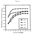
- Fig. 14 is a view showing cycle test results on a hydrogen absorbing electrode of example 3.
- Fig. 15 is a view showing X-ray diffraction peaks of the hydrogen absorbing alloy obtained when setting a temperature of acid treatment to 80°C to 90°C in the example 3.
- Fig. 16 is a view showing X-ray diffraction peaks of the hydrogen absorbing alloy of comparison example 1.
- Fig. 13 is a view showing cycle test results on the hydrogen absorbing electrode of example 2.
- Fig. 14 is a view showing cycle test results on a hydrogen absorbing electrode of example 3.
- Fig. 15 is a view showing X-ray diffraction peaks of the hydrogen absorbing alloy obtained when setting a temperature of acid treatment to 80°C to 90°C in the example 3.
- FIG. 17 is a view showing measured results of gas generation amount at the end of initial charge on the hydrogen absorbing electrode obtained when setting the temperature of acid treatment temperature to 80°C to 90°C in the example 3 and on the hydrogen absorbing electrode of comparison example 1.
- Fig. 18 is a view showing changes of initial discharge capacities on a hydrogen absorbing electrode of example 4, the hydrogen absorbing electrode of comparison example 1 and the hydrogen absorbing electrode of comparison example 2.
- Fig. 19 is a view showing cycle test results on a hydrogen absorbing electrode of example 5 and a hydrogen absorbing electrode of comparison example 4.
- Fig. 20 is a view showing cycle test results on a battery using a hydrogen absorbing electrode of example 6 and a battery using a hydrogen absorbing electrode of comparison example 5.
- a hydrogen absorbing alloy ingot having a composition of MmNi 3.8 Al 0.3 Co 0.7 Mn 0.2 was made up and ground by machine to prepare alloy particles having appropriate sizes (grain size of 75 ⁇ m or smaller).
- Mm is a misch metal forming a composite comprising rare earth elements of one or more kinds of La, Ce, Pr and Nd.
- the alloy particles were dipped in acetic acid/sodium acetate buffer solution adjusted to 60°C and pH3.6, stirred, rinsed and dried. In other words, the alloy particles were subjected to the acid treatment. Since the acetic acid/sodium acetate buffer solution was used, the pH was easily set and its fluctuation was small too.
- the prepared alloy particles were added with a binder to be formed into a paste, filled in a nickel fiber substrate and dried, then it was pressed so that a hydrogen absorbing electrode was made up.
- the alloy particles after undergoing the acid treatment were subjected to surface analysis by X-ray photoelectron spectroscopy (XPS), high-magnification surface observation by transmission-type electron microscope (TEM), element analysis and electron beam diffraction. It was found that the alloy particle had a sectional structure as shown in Fig. 1. Namely, a rich layer 2 was produced on an alloy particle surface by the acid treatment. 1 is a bulk. Fig. 2 shows an alloy composition ratio of a part corresponding to that of Fig. 1. The bulk 1 is a part having a composition of MmNi 3.8 Al 0.3 Co 0.7 Mn 0.2 which is an original composition. The rich layer 2 had a thickness of 50 to 300 nm.
- XPS X-ray photoelectron spectroscopy
- TEM transmission-type electron microscope
- the thickness of rich layer 2 is controlled by a dipping time of the acid treatment.
- the rich layer 2 has a larger inclusion percentage of transition metals such as Ni, Co and Mn etc. as compared with the bulk 1, mainly because of elusion of Al and the rare earth elements in Mm.
- Pore diameter distribution was measured on the alloy particles after undergoing acid treatment.
- Fig. 3 shows measured results of pore diameter distribution measured from an absorption side.
- the surface of alloy particle had a structure mainly including fine pores having diameters of several tens of angstroms.
- the surface area was calculated as about 400 m2/g from specific surface area measurement results, and this value was fairly large.
- the alloy particles visually presented black color due to irregular reflection.
- a hydrogen absorbing electrode was made up in the same way as that of example 1 except that the acid treatment was not done.
- a hydrogen absorbing electrode was made up in the same way as that of example 1 except that alkali treatment using alkali aqueous solution was done in place of the acid treatment.
- the dipping time in the acid treatment of example 1 was prolonged to form a rich layer thicker than 300 ⁇ m.
- Other conditions were made identical with those of example 1.
- a hydrogen absorbing electrode was made up in the same way as the example 1 except that the pH values in the acid treatment of example 1 were set to six kinds. The pH values were set to 2.09, 2.71, 3.59, 4.00, 4.71 and 5.96.
- the prepared hydrogen absorbing electrodes were subjected to cycle tests, and the all electrodes presented initial characteristics same with those of the example 1 as illustrated in Fig. 13. From this fact, it can be understood that the rich layer 2 similar to that of example 1 is produced provided that the pH value lies within a range from 2 to 6.
- a hydrogen absorbing electrode was made up in the same way as the example 1 except that temperatures in the acid treatment of example 1 were set to four kinds. The temperatures were set to 20°C, 40°C, 60°C, and 80°C through 90°C.
- X-ray diffractions were measured on the hydrogen absorbing alloy after undergoing acid treatment at 80°C through 90°C and the hydrogen absorbing alloy of comparison example 1.
- Fig. 15 shows X-ray diffraction peaks of the alloy after undergoing the acid treatment at 80°C through 90°C
- Fig. 16 shows X-ray diffraction peaks of the alloy of comparison example 1.
- Ni-peak is seen in the alloy after undergoing the acid treatment at 80°C through 90°C. Namely, the rich layer is produced on the alloy surface, and Ni layer is further produced on a surface of the rich layer.
- FIG. 17 shows gas generation amounts at the end of initial discharge on the hydrogen absorbing electrode in case of 80°C through 90°C and the hydrogen absorbing electrode of comparison example 1.
- a battery using the electrode in case of 80°C through 90°C is reduced in a rise of inside pressure as compared with the electrode of comparison example 1.
- the hydrogen absorbing electrode prepared by setting the temperature condition of acid treatment to 80°C through 90°C the activation becomes unnecessary because the rich layer is produced, and the gas absorbing ability is improved because the Ni layer is produced on the surface of rich layer.
- Alloy particles prepared in the same way as the example 1 were dipped in acetic acid aqueous solution adjusted to 60°C and pH 2.7, stirred and rinsed and then dried. In other words, the alloy particles were subjected to acid treatment.
- the prepared alloy particles were added with a binder to be formed into a paste, filled in a nickel-fiber substrate, dried and pressed so that a hydrogen absorbing electrode was made up.
- a rich layer similar to that of example 4 will be produced even when using other organic acids such as formic acid, acetic acid, propionic acid, butyric acid, malonic acid, oxalic acid, acrylic acid, valeric acid, glycolic acid, citric acid, succinic acid, glutaric acid, lactic acid and tartaric acid etc., in place of the acetic acid.
- organic acids such as formic acid, acetic acid, propionic acid, butyric acid, malonic acid, oxalic acid, acrylic acid, valeric acid, glycolic acid, citric acid, succinic acid, glutaric acid, lactic acid and tartaric acid etc.
- a hydrogen absorbing electrode was made up in the same way as the example 1 except that a hydrogen absorbing alloy having a composition of MmNi 3.8 Al 0.5 Co 0.7 was used.
- a hydrogen absorbing electrode was made up in the same way as the example 5 except that the acid treatment was not done.
- a hydrogen absorbing alloy having the composition of MmNi 3.8 Al 0.3 Co 0.7 Mn 0.2 was weighed, thrown in a crucible, and then molten by a high-frequency melting furnace under an atmosphere of inert gas, so as to make up a hydrogen absorbing alloy ingot.
- This alloy ingot was rough ground mechanically to classify only particles within a grain size range of 75 to 150 ⁇ m by using a screen.
- the classified particles were further rough ground mechanically to classify only particles within a grain size range of 45 to 75 ⁇ m by using a screen, so that alloy particles were prepared.
- the alloy particles were dipped in acetic acid/sodium acetate buffer solution adjusted to 60°C and pH 3.6, stirred and rinsed and then dried. In other words, the alloy particles were subjected to acid treatment.
- the prepared alloy particles were added with binder to be formed into a paste, filled in a nickel-fiber substrate, dried and pressed so that a hydrogen absorbing electrode was made up.
- the alloy particles after undergoing the acid treatment were subjected to surface analysis by X-ray photoelectron spectroscopy (XPS), high-magnification surface observation by transmission-type electron microscope (TEM), element analysis and electron beam diffraction. It was found that the alloy particles had a sectional structure similar to the alloy particles of example 1. Namely, a rich layer 2 having a larger inclusion percentage of transition metal such as Ni, Co & Mn etc. than that of the bulk 1, was produced on a surface of the bulk 1.
- XPS X-ray photoelectron spectroscopy
- TEM transmission-type electron microscope
- a hydrogen absorbing electrode was made up in the same way as the example 6 except that the acid treatment was not done.
- characteristics of a hydrogen absorbing electrode can be improved and the hydrogen absorbing electrode can be manufactured easily. Therefore, this invention can be utilized effectively for a nickel-hydride secondary battery.
Landscapes
- Chemical & Material Sciences (AREA)
- Chemical Kinetics & Catalysis (AREA)
- General Chemical & Material Sciences (AREA)
- Electrochemistry (AREA)
- Battery Electrode And Active Subsutance (AREA)
- Powder Metallurgy (AREA)
Applications Claiming Priority (11)
| Application Number | Priority Date | Filing Date | Title |
|---|---|---|---|
| JP27189/94 | 1994-02-25 | ||
| JP2718994 | 1994-02-25 | ||
| JP149142/94 | 1994-06-30 | ||
| JP14914294 | 1994-06-30 | ||
| JP266564/94 | 1994-10-31 | ||
| JP26656494 | 1994-10-31 | ||
| JP274822/94 | 1994-11-09 | ||
| JP27482294 | 1994-11-09 | ||
| JP276899/94 | 1994-11-11 | ||
| JP27689994 | 1994-11-11 | ||
| PCT/JP1995/000262 WO1995023435A1 (fr) | 1994-02-25 | 1995-02-23 | Electrode absorbant l'hydrogene et son procede de production |
Publications (3)
| Publication Number | Publication Date |
|---|---|
| EP0696823A1 true EP0696823A1 (de) | 1996-02-14 |
| EP0696823A4 EP0696823A4 (de) | 1996-04-24 |
| EP0696823B1 EP0696823B1 (de) | 1998-10-28 |
Family
ID=27520906
Family Applications (1)
| Application Number | Title | Priority Date | Filing Date |
|---|---|---|---|
| EP95909963A Expired - Lifetime EP0696823B1 (de) | 1994-02-25 | 1995-02-23 | Wasserstoffabsorbierende elektrode und deren herstellung |
Country Status (5)
| Country | Link |
|---|---|
| US (1) | US5935732A (de) |
| EP (1) | EP0696823B1 (de) |
| JP (1) | JP3661190B2 (de) |
| DE (1) | DE69505611T2 (de) |
| WO (1) | WO1995023435A1 (de) |
Cited By (9)
| Publication number | Priority date | Publication date | Assignee | Title |
|---|---|---|---|---|
| EP0843371A1 (de) * | 1996-11-18 | 1998-05-20 | Shin-Etsu Chemical Co., Ltd. | Wasserstoffspeicherlegierungspulver und dieser enthaltende Elektrode |
| EP0845823A1 (de) * | 1996-11-29 | 1998-06-03 | SANYO ELECTRIC Co., Ltd. | Elektrode aus Wasserstoffspeicherlegierung, Verfahren zur Herstellung und alkalische Sekundärbatterie |
| EP0823134A4 (de) * | 1995-04-17 | 1998-08-12 | Ovonic Battery Co | Elektrochemische wasserstoffspeicherlegierungen für nickelmetalhydridbatterien |
| EP0867956A1 (de) * | 1997-03-24 | 1998-09-30 | Matsushita Electric Industrial Co., Ltd. | Elektrode aus wasserstoffspeichernder Legierung |
| EP0944124A1 (de) * | 1998-02-19 | 1999-09-22 | Matsushita Electric Industrial Co., Ltd. | Wasserstoffabsorbierende Legierung für Batterien, Verfahren zu ihrer Herstellung und alkalische Speicherbatterie die diese Legierung verwendet |
| EP0986119A1 (de) * | 1998-09-11 | 2000-03-15 | Matsushita Electric Industrial Co., Ltd. | Alkalische Batterie, Elektrode aus einer wasserstoffabsorbierenden Legierung und Herstellungsverfahren dafür |
| EP0945907A4 (de) * | 1996-06-26 | 2002-01-16 | Sanyo Electric Co | Wasserstoffspeicherlegierungselektrode und verfahren zu deren herstellung |
| EP0975033A4 (de) * | 1997-01-31 | 2006-05-24 | Sanyo Electric Co | Wasserstoffspeicherlegierungspulver und verfahren zu dessen herstellung |
| US7820325B2 (en) | 2005-05-26 | 2010-10-26 | Saft | Alkaline electrolyte storage battery having an anode formed of an active material composition |
Families Citing this family (9)
| Publication number | Priority date | Publication date | Assignee | Title |
|---|---|---|---|---|
| JP3033430B2 (ja) | 1994-04-27 | 2000-04-17 | 住友金属工業株式会社 | 水素吸蔵合金粉末とニッケル−水素電池 |
| US6235130B1 (en) * | 1998-03-17 | 2001-05-22 | Shin-Etsu Chemical Co., Ltd. | Hydrogen absorbing alloy powder and electrodes formed of the hydrogen absorbing alloy powder |
| WO2000001023A1 (fr) * | 1998-06-26 | 2000-01-06 | Sanyo Electric Co., Ltd. | Alliage absorbeur d'hydrogene pour batteries alcalines et procede de preparation associe |
| US20040018450A1 (en) * | 2002-07-25 | 2004-01-29 | United Microlectronics Corp. | Method for transferring patterns |
| WO2009132036A1 (en) * | 2008-04-21 | 2009-10-29 | Quantumsphere, Inc. | Composition of and method of using nanoscale materials in hydrogen storage applications |
| US10017656B2 (en) | 2015-05-18 | 2018-07-10 | Canon Kabushiki Kaisha | Image recording method, treatment liquid and ink set |
| EP3653296B1 (de) * | 2017-07-12 | 2023-12-13 | Japan Science and Technology Agency | Intermetallische verbindung, wasserstoffspeicher-/freisetzungsmaterial, katalysator und verfahren zur herstellung von ammoniak |
| WO2020195543A1 (ja) * | 2019-03-26 | 2020-10-01 | 日本重化学工業株式会社 | アルカリ蓄電池用水素吸蔵合金およびそれを負極に用いたアルカリ蓄電池ならびに車両 |
| US12266791B2 (en) | 2020-04-10 | 2025-04-01 | Japan Metals And Chemicals Co., Ltd. | Hydrogen storage alloy for alkaline storage battery |
Family Cites Families (11)
| Publication number | Priority date | Publication date | Assignee | Title |
|---|---|---|---|---|
| EP0271043B1 (de) * | 1986-12-08 | 1992-01-22 | Matsushita Electric Industrial Co., Ltd. | Gasdichter Akkumulator und Verfahren zur Herstellung seiner Elektrode |
| JP2733231B2 (ja) * | 1987-11-17 | 1998-03-30 | 松下電器産業株式会社 | 水素吸蔵合金電極の製造法 |
| US4859413A (en) * | 1987-12-04 | 1989-08-22 | The Standard Oil Company | Compositionally graded amorphous metal alloys and process for the synthesis of same |
| JP2994664B2 (ja) * | 1989-09-05 | 1999-12-27 | 三洋電機株式会社 | 水素吸蔵合金電極の製造方法 |
| JP2854109B2 (ja) * | 1990-08-29 | 1999-02-03 | 三洋電機株式会社 | 水素吸蔵合金電極の製造方法 |
| JPH04318106A (ja) * | 1991-04-17 | 1992-11-09 | Furukawa Battery Co Ltd:The | 水素吸蔵合金粉末の製造法 |
| JPH04319258A (ja) * | 1991-04-17 | 1992-11-10 | Furukawa Battery Co Ltd:The | 水素吸蔵合金電極 |
| JPH05225974A (ja) * | 1992-02-10 | 1993-09-03 | Furukawa Battery Co Ltd:The | 水素吸蔵合金電極 |
| JPH05225975A (ja) * | 1992-02-13 | 1993-09-03 | Furukawa Battery Co Ltd:The | 水素吸蔵合金電極 |
| JPH06223827A (ja) * | 1992-10-26 | 1994-08-12 | Sumitomo Metal Ind Ltd | 電池用水素吸蔵合金粉末の製造方法 |
| JPH0773878A (ja) * | 1993-08-31 | 1995-03-17 | Sanyo Electric Co Ltd | 金属水素化物電極の製造方法 |
-
1995
- 1995-02-23 WO PCT/JP1995/000262 patent/WO1995023435A1/ja not_active Ceased
- 1995-02-23 JP JP52225595A patent/JP3661190B2/ja not_active Expired - Lifetime
- 1995-02-23 EP EP95909963A patent/EP0696823B1/de not_active Expired - Lifetime
- 1995-02-23 DE DE69505611T patent/DE69505611T2/de not_active Expired - Fee Related
-
1997
- 1997-06-10 US US08/872,192 patent/US5935732A/en not_active Expired - Lifetime
Cited By (17)
| Publication number | Priority date | Publication date | Assignee | Title |
|---|---|---|---|---|
| EP0823134A4 (de) * | 1995-04-17 | 1998-08-12 | Ovonic Battery Co | Elektrochemische wasserstoffspeicherlegierungen für nickelmetalhydridbatterien |
| EP0945907A4 (de) * | 1996-06-26 | 2002-01-16 | Sanyo Electric Co | Wasserstoffspeicherlegierungselektrode und verfahren zu deren herstellung |
| EP1713139A1 (de) * | 1996-06-26 | 2006-10-18 | Sanyo Electric Co., Ltd. | Wasserstoffspeicher-Legierungselektrode und zugehöriges Herstellungsverfahren |
| EP0843371A1 (de) * | 1996-11-18 | 1998-05-20 | Shin-Etsu Chemical Co., Ltd. | Wasserstoffspeicherlegierungspulver und dieser enthaltende Elektrode |
| US5968225A (en) * | 1996-11-18 | 1999-10-19 | Shin-Etsu Chemical Co., Ltd. | Hydrogen storage alloy powder and an electrode comprising the same |
| EP0845823A1 (de) * | 1996-11-29 | 1998-06-03 | SANYO ELECTRIC Co., Ltd. | Elektrode aus Wasserstoffspeicherlegierung, Verfahren zur Herstellung und alkalische Sekundärbatterie |
| US5985057A (en) * | 1996-11-29 | 1999-11-16 | Sanyo Electric Co., Ltd. | Method of fabricating hydrogen absorbing alloy electrode |
| EP0975033A4 (de) * | 1997-01-31 | 2006-05-24 | Sanyo Electric Co | Wasserstoffspeicherlegierungspulver und verfahren zu dessen herstellung |
| EP0867956A1 (de) * | 1997-03-24 | 1998-09-30 | Matsushita Electric Industrial Co., Ltd. | Elektrode aus wasserstoffspeichernder Legierung |
| US6048644A (en) * | 1997-03-24 | 2000-04-11 | Matsushita Electric Industrial Co., Ltd. | Hydrogen storage alloy electrode |
| EP0944124A1 (de) * | 1998-02-19 | 1999-09-22 | Matsushita Electric Industrial Co., Ltd. | Wasserstoffabsorbierende Legierung für Batterien, Verfahren zu ihrer Herstellung und alkalische Speicherbatterie die diese Legierung verwendet |
| US6740450B2 (en) | 1998-02-19 | 2004-05-25 | Matsushita Electric Industrial Co., Ltd. | Hydrogen-absorbing alloy for battery, method for producing the same, and alkaline storage battery using the same |
| CN1130783C (zh) * | 1998-09-11 | 2003-12-10 | 松下电器产业株式会社 | 碱性蓄电池、吸氢合金电极及其生产方法 |
| US6699617B2 (en) | 1998-09-11 | 2004-03-02 | Matsushita Electric Industrial Co., Ltd. | Alkaline storage battery, hydrogen-absorbing alloy electrode and method for producing the same |
| US6331367B1 (en) | 1998-09-11 | 2001-12-18 | Matsushita Electric Industrial Co., Ltd. | Alkaline storage battery hydrogen-absorbing alloy electrode and method for producing the same |
| EP0986119A1 (de) * | 1998-09-11 | 2000-03-15 | Matsushita Electric Industrial Co., Ltd. | Alkalische Batterie, Elektrode aus einer wasserstoffabsorbierenden Legierung und Herstellungsverfahren dafür |
| US7820325B2 (en) | 2005-05-26 | 2010-10-26 | Saft | Alkaline electrolyte storage battery having an anode formed of an active material composition |
Also Published As
| Publication number | Publication date |
|---|---|
| DE69505611T2 (de) | 1999-03-25 |
| EP0696823A4 (de) | 1996-04-24 |
| EP0696823B1 (de) | 1998-10-28 |
| DE69505611D1 (de) | 1998-12-03 |
| WO1995023435A1 (fr) | 1995-08-31 |
| US5935732A (en) | 1999-08-10 |
| JP3661190B2 (ja) | 2005-06-15 |
Similar Documents
| Publication | Publication Date | Title |
|---|---|---|
| US5935732A (en) | Hydrogen absorbing electrode and its manufacturing method | |
| US5695530A (en) | Method for making high charging efficiency and fast oxygen recombination rechargeable hydride batteries | |
| JPWO1995023435A1 (ja) | 水素吸蔵電極及びその製造方法 | |
| JPH05225975A (ja) | 水素吸蔵合金電極 | |
| US6524746B2 (en) | Hydrogen absorbing alloy powder and process for producing same | |
| CA2321293C (en) | Nickel electrode for alkali storage battery, method of producing nickel electrode for alkali storage battery, and alkali storage battery | |
| EP1271677B1 (de) | Elektrode aus Wasserstoff absorbierender Legierung | |
| EP1713139A1 (de) | Wasserstoffspeicher-Legierungselektrode und zugehöriges Herstellungsverfahren | |
| JP2925604B2 (ja) | アルカリ二次電池用水素吸蔵合金の処理方法 | |
| JP4497828B2 (ja) | ニッケル−水素蓄電池および組電池 | |
| JPH10162820A (ja) | アルカリ蓄電池用水素吸蔵合金の製造方法 | |
| US6852447B2 (en) | Metal hydride alkaline storage cell and manufacturing method thereof | |
| JP3478030B2 (ja) | アルカリ蓄電池 | |
| JP2002343349A (ja) | 水素吸蔵合金電極 | |
| JP3433008B2 (ja) | アルカリ蓄電池用水素吸蔵合金の製造方法 | |
| JPH08333603A (ja) | 水素吸蔵合金粒子およびその製造方法 | |
| JPH0815078B2 (ja) | 水素吸蔵電極の製造方法 | |
| JP2002141061A (ja) | 水素吸蔵合金電極およびその製造方法 | |
| JP3322415B2 (ja) | 金属−水素アルカリ蓄電池及びその製造方法 | |
| JP3499923B2 (ja) | 金属−水素化物アルカリ蓄電池用の水素吸蔵合金電極及び金属−水素化物アルカリ蓄電池用の水素吸蔵合金粒子 | |
| JP3369148B2 (ja) | アルカリ蓄電池 | |
| JP2001006666A (ja) | アルカリ蓄電池用水素吸蔵合金及びその製造方法 | |
| JPH10172550A (ja) | ニッケル正極をもつアルカリ電池及びその活性化方法 | |
| JPH11191412A (ja) | アルカリ蓄電池 | |
| JP3614567B2 (ja) | 密閉形ニッケル水素電池 |
Legal Events
| Date | Code | Title | Description |
|---|---|---|---|
| PUAI | Public reference made under article 153(3) epc to a published international application that has entered the european phase |
Free format text: ORIGINAL CODE: 0009012 |
|
| 17P | Request for examination filed |
Effective date: 19951114 |
|
| AK | Designated contracting states |
Kind code of ref document: A1 Designated state(s): DE FR GB |
|
| A4 | Supplementary search report drawn up and despatched | ||
| AK | Designated contracting states |
Kind code of ref document: A4 Designated state(s): DE FR GB |
|
| 17Q | First examination report despatched |
Effective date: 19970514 |
|
| GRAG | Despatch of communication of intention to grant |
Free format text: ORIGINAL CODE: EPIDOS AGRA |
|
| GRAG | Despatch of communication of intention to grant |
Free format text: ORIGINAL CODE: EPIDOS AGRA |
|
| GRAH | Despatch of communication of intention to grant a patent |
Free format text: ORIGINAL CODE: EPIDOS IGRA |
|
| GRAH | Despatch of communication of intention to grant a patent |
Free format text: ORIGINAL CODE: EPIDOS IGRA |
|
| GRAA | (expected) grant |
Free format text: ORIGINAL CODE: 0009210 |
|
| AK | Designated contracting states |
Kind code of ref document: B1 Designated state(s): DE FR GB |
|
| REF | Corresponds to: |
Ref document number: 69505611 Country of ref document: DE Date of ref document: 19981203 |
|
| ET | Fr: translation filed | ||
| PLBE | No opposition filed within time limit |
Free format text: ORIGINAL CODE: 0009261 |
|
| STAA | Information on the status of an ep patent application or granted ep patent |
Free format text: STATUS: NO OPPOSITION FILED WITHIN TIME LIMIT |
|
| 26N | No opposition filed | ||
| REG | Reference to a national code |
Ref country code: GB Ref legal event code: IF02 |
|
| PGFP | Annual fee paid to national office [announced via postgrant information from national office to epo] |
Ref country code: DE Payment date: 20060216 Year of fee payment: 12 |
|
| PGFP | Annual fee paid to national office [announced via postgrant information from national office to epo] |
Ref country code: FR Payment date: 20060220 Year of fee payment: 12 |
|
| PGFP | Annual fee paid to national office [announced via postgrant information from national office to epo] |
Ref country code: GB Payment date: 20060222 Year of fee payment: 12 |
|
| GBPC | Gb: european patent ceased through non-payment of renewal fee |
Effective date: 20070223 |
|
| REG | Reference to a national code |
Ref country code: FR Ref legal event code: ST Effective date: 20071030 |
|
| PG25 | Lapsed in a contracting state [announced via postgrant information from national office to epo] |
Ref country code: DE Free format text: LAPSE BECAUSE OF NON-PAYMENT OF DUE FEES Effective date: 20070901 |
|
| PG25 | Lapsed in a contracting state [announced via postgrant information from national office to epo] |
Ref country code: GB Free format text: LAPSE BECAUSE OF NON-PAYMENT OF DUE FEES Effective date: 20070223 Ref country code: FR Free format text: LAPSE BECAUSE OF NON-PAYMENT OF DUE FEES Effective date: 20070228 |