EP0701025A2 - Zweikomponenten-Mischsystem zum Beschichten - Google Patents
Zweikomponenten-Mischsystem zum Beschichten Download PDFInfo
- Publication number
- EP0701025A2 EP0701025A2 EP95113421A EP95113421A EP0701025A2 EP 0701025 A2 EP0701025 A2 EP 0701025A2 EP 95113421 A EP95113421 A EP 95113421A EP 95113421 A EP95113421 A EP 95113421A EP 0701025 A2 EP0701025 A2 EP 0701025A2
- Authority
- EP
- European Patent Office
- Prior art keywords
- main agent
- hardening agent
- coating
- agent
- tank
- Prior art date
- Legal status (The legal status is an assumption and is not a legal conclusion. Google has not performed a legal analysis and makes no representation as to the accuracy of the status listed.)
- Ceased
Links
Images


Classifications
-
- B—PERFORMING OPERATIONS; TRANSPORTING
- B29—WORKING OF PLASTICS; WORKING OF SUBSTANCES IN A PLASTIC STATE IN GENERAL
- B29B—PREPARATION OR PRETREATMENT OF THE MATERIAL TO BE SHAPED; MAKING GRANULES OR PREFORMS; RECOVERY OF PLASTICS OR OTHER CONSTITUENTS OF WASTE MATERIAL CONTAINING PLASTICS
- B29B7/00—Mixing; Kneading
- B29B7/74—Mixing; Kneading using other mixers or combinations of mixers, e.g. of dissimilar mixers ; Plant
- B29B7/7404—Mixing devices specially adapted for foamable substances
- B29B7/7409—Mixing devices specially adapted for foamable substances with supply of gas
-
- B—PERFORMING OPERATIONS; TRANSPORTING
- B01—PHYSICAL OR CHEMICAL PROCESSES OR APPARATUS IN GENERAL
- B01F—MIXING, e.g. DISSOLVING, EMULSIFYING OR DISPERSING
- B01F35/00—Accessories for mixers; Auxiliary operations or auxiliary devices; Parts or details of general application
- B01F35/80—Forming a predetermined ratio of the substances to be mixed
- B01F35/83—Forming a predetermined ratio of the substances to be mixed by controlling the ratio of two or more flows, e.g. using flow sensing or flow controlling devices
-
- B—PERFORMING OPERATIONS; TRANSPORTING
- B01—PHYSICAL OR CHEMICAL PROCESSES OR APPARATUS IN GENERAL
- B01F—MIXING, e.g. DISSOLVING, EMULSIFYING OR DISPERSING
- B01F35/00—Accessories for mixers; Auxiliary operations or auxiliary devices; Parts or details of general application
- B01F35/80—Forming a predetermined ratio of the substances to be mixed
- B01F35/83—Forming a predetermined ratio of the substances to be mixed by controlling the ratio of two or more flows, e.g. using flow sensing or flow controlling devices
- B01F35/833—Flow control by valves, e.g. opening intermittently
-
- B—PERFORMING OPERATIONS; TRANSPORTING
- B29—WORKING OF PLASTICS; WORKING OF SUBSTANCES IN A PLASTIC STATE IN GENERAL
- B29B—PREPARATION OR PRETREATMENT OF THE MATERIAL TO BE SHAPED; MAKING GRANULES OR PREFORMS; RECOVERY OF PLASTICS OR OTHER CONSTITUENTS OF WASTE MATERIAL CONTAINING PLASTICS
- B29B7/00—Mixing; Kneading
- B29B7/30—Mixing; Kneading continuous, with mechanical mixing or kneading devices
- B29B7/58—Component parts, details or accessories; Auxiliary operations
- B29B7/60—Component parts, details or accessories; Auxiliary operations for feeding, e.g. end guides for the incoming material
- B29B7/603—Component parts, details or accessories; Auxiliary operations for feeding, e.g. end guides for the incoming material in measured doses, e.g. proportioning of several materials
-
- B—PERFORMING OPERATIONS; TRANSPORTING
- B29—WORKING OF PLASTICS; WORKING OF SUBSTANCES IN A PLASTIC STATE IN GENERAL
- B29B—PREPARATION OR PRETREATMENT OF THE MATERIAL TO BE SHAPED; MAKING GRANULES OR PREFORMS; RECOVERY OF PLASTICS OR OTHER CONSTITUENTS OF WASTE MATERIAL CONTAINING PLASTICS
- B29B7/00—Mixing; Kneading
- B29B7/30—Mixing; Kneading continuous, with mechanical mixing or kneading devices
- B29B7/58—Component parts, details or accessories; Auxiliary operations
- B29B7/72—Measuring, controlling or regulating
-
- B—PERFORMING OPERATIONS; TRANSPORTING
- B29—WORKING OF PLASTICS; WORKING OF SUBSTANCES IN A PLASTIC STATE IN GENERAL
- B29B—PREPARATION OR PRETREATMENT OF THE MATERIAL TO BE SHAPED; MAKING GRANULES OR PREFORMS; RECOVERY OF PLASTICS OR OTHER CONSTITUENTS OF WASTE MATERIAL CONTAINING PLASTICS
- B29B7/00—Mixing; Kneading
- B29B7/74—Mixing; Kneading using other mixers or combinations of mixers, e.g. of dissimilar mixers ; Plant
- B29B7/7404—Mixing devices specially adapted for foamable substances
- B29B7/7409—Mixing devices specially adapted for foamable substances with supply of gas
- B29B7/7428—Methodical aspects
-
- B—PERFORMING OPERATIONS; TRANSPORTING
- B29—WORKING OF PLASTICS; WORKING OF SUBSTANCES IN A PLASTIC STATE IN GENERAL
- B29B—PREPARATION OR PRETREATMENT OF THE MATERIAL TO BE SHAPED; MAKING GRANULES OR PREFORMS; RECOVERY OF PLASTICS OR OTHER CONSTITUENTS OF WASTE MATERIAL CONTAINING PLASTICS
- B29B7/00—Mixing; Kneading
- B29B7/74—Mixing; Kneading using other mixers or combinations of mixers, e.g. of dissimilar mixers ; Plant
- B29B7/7438—Mixing guns, i.e. hand-held mixing units having dispensing means
- B29B7/7447—Mixing guns, i.e. hand-held mixing units having dispensing means including means for feeding the components
-
- B—PERFORMING OPERATIONS; TRANSPORTING
- B29—WORKING OF PLASTICS; WORKING OF SUBSTANCES IN A PLASTIC STATE IN GENERAL
- B29B—PREPARATION OR PRETREATMENT OF THE MATERIAL TO BE SHAPED; MAKING GRANULES OR PREFORMS; RECOVERY OF PLASTICS OR OTHER CONSTITUENTS OF WASTE MATERIAL CONTAINING PLASTICS
- B29B7/00—Mixing; Kneading
- B29B7/80—Component parts, details or accessories; Auxiliary operations
- B29B7/802—Constructions or methods for cleaning the mixing or kneading device
- B29B7/803—Cleaning of mixers of the gun type, stream-impigement type, mixing heads
- B29B7/805—Cleaning of the mixing conduit, module or chamber part
Definitions
- the present invention relates to a dual components mixing system for coating which mixes main agent and hardening agent right before supplying to a coating gun, and more particularly, a manually operated coating gun.
- urethane coating is used by mixing with hardening agent right before coating by a coating gun.
- a coating gun As such systems which mix main agent and hardening agent, dual components mixing systems described in Japanese patent laid-open disclosure No. 5-49977 and Japanese patent public disclosure No. 5-41305 are known.
- the dual components mixing system disclosed in Japanese patent public disclosure No. 5-41305 is constituted in such a way that main agent, hardening agent, and thinner for dilution are fed to a mixer through separate lines. After they are mixed together by the mixer, the mixture is supplied to a manually operated gun. Further more, in order to control a mixture ratio of the main agent and hardening agent, a gear-pump is utilized. It is constituted so that the mixture ratio of the main agent and hardening agent equals a predetermined value by regulating each ratio of rotation of a gear-pump for main agents and a gear pump for hardening agents.
- the object of the present invention to provide a dual components mixing system having an automatic control system for controlling the mixture ratio of a main agent and a hardening agent that is suitable for manually operated guns.
- a dual components mixing system for coating comprising: a first tank containing main agent; a second tank containing hardening agent diluted with thinner; a mixer which mixes the main agent and the hardening agent and adapted for supplying the mixture to a manually operated coating gun; a main agent conduit which connects the mixer with said first tank; a hardening agent conduit which connects said mixer with said second tank; means for detecting flow rate of the main agent disposed on said main agent conduit; means for detecting flow rate of the hardening agent disposed on said hardening agent conduit; flow regulating means disposed on said hardening agent conduit on the upstream side of said means for detecting flow rate; and feedback control means for receiving signals from said means for detecting flow rate of the main agent and said means for detecting flow rate of the hardening agent, and controlling said flow regulating means so that the ratio of the hardening agent is a predetermined mixture ratio with respect to the amount of main agent detected by said means for detecting flow rate of the
- the flow rate of hardening agent is constituted in such a way to follow up the flow rate of main agent, it is relatively easy to construct a control system for controlling the mixture of dual components coated by the manually operated coating gun whereas it is usually difficult to set a target value for controlling both main agent and hardening agent.
- the control accuracy can be improved compared with a case where its volume is not increased.
- the control system itself can be designed with less accuracy. Therefore, the manufacturing cost of the system can be reduced.
- a dual components mixing system for coating further comprises: memory means for storing a plurality of values detected by said means for detecting flow rate of hardening agent in chronological order; an operation detecting sensor for detecting on/off of said manually operated coating gun; operation interruption detecting means for detecting interruption of the operation of said manually operated coating gun; target values setting means for receiving a signal from said operation interruption detecting means and said operation detecting sensor, and setting a value corresponding to the value which is stored previously to the storing of one or more values among the values stored in said memory means as a target value for said feedback control means if said operation detecting sensor detects that said manually operated coating gun is switched on after the operation of said manually operated coating gun is interrupted; control mode changing means for switching to an ordinary feedback control by said feedback control means when a predetermined length of time has been passed after said target values setting means sets said target value.
- the data value which is the one stored previously to the storing of one or more values among the values stored in said memory means as a target value i.e., it is the data value detected before the interruption of the coating operation
- a dual components mixing system for coating further comprises: a target value input means for allowing a manual input of the target value of said feedback control; target value changing means for changing, upon receiving a signal from said operation detecting means, the target value to the inputted target value as a target value of said feedback control means when said manually operated coating gun is switched on.
- a target value input means for allowing a manual input of the target value of said feedback control
- target value changing means for changing, upon receiving a signal from said operation detecting means, the target value to the inputted target value as a target value of said feedback control means when said manually operated coating gun is switched on.
- an upstream portion of said main agent conduit is provided with a common flow path whose upstream end is closed; and further comprising, a first three ports two position valve disposed on said common flow path; a second three ports two position valve disposed on said common flow path; a first on-off type valve disposed on the upstream end of said common flow path; said first three ports two position valve is connected with a first branch pipe to which said first tank is releasably joined with and a first drain pipe which a first on-off type valve for drainage is disposed thereto; said second three ports two position valve is connected with a second branch pipe which a sub-tank containing main agent which is different from the main agent contained in said first tank is releasably connected therewith, and a second drain pipe which a second on-off type valve for drainage is disposed thereto; said first on-off type valve is connected with a cleaning pipe that extends from a cleaning pot which ejects cleaning fluid and air alternatively.
- a dual components mixing system for coating further comprises: a manually operated coating gun for coating.
- Figure 1 is a schematic diagram of a dual components mixing system according to a preferred embodiment showing in general.
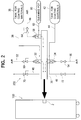
- Figure 2 is a schematic diagram of a coating materials color changing unit.
- Figure 3 is a flow chart showing an example of control flow by a controller U.
- FIG 1 is a schematic diagram of a dual components mixing system according to a preferred embodiment showing in general.
- the dual components mixing system 100 comprises a main agent inlet 2 for receiving a main agent and a hardening agent inlet 4 for receiving a hardening agent.
- the main agent inlet 2 may be connected with, for example, any coating material supply system having a pressure tank, a diaphragm pump, or a plunger pump which are commonly used.
- a coating material color changing unit 200 shown in Figure 2 is connected therewith. The details of the coating material color changing unit 200 will be explained below.
- the hardening agent inlet 4 is connected with a pipe extended from a tank for hardening agents (not shown) and a hardening agent contained in the tank is delivered to the inlet 4 under pressure by a pump (not shown).
- the dual components mixing system 100 includes a mixer 6 for mixing a coating material (i.e., main agent) and a hardening agent.
- a dual components mixture which contains the main agent and hardening agent mixed by the mixer 6 is supplied to a manually controlled spray gun 10 through a flexible tube 8 and is sprayed onto an object (not shown) thereby.
- the mixer 6 is connected with the main agent inlet 2 through a main agent conduit or a tube 12 and is connected with the hardening agent inlet 4 through a hardening agent conduit or a tube 14.
- the main agent conduit 12 is provided with a flow meter for main agents such as a gear-rotor type flow meter or the like which detects flow rate of main agent and a check valve 18 on the upstream side directly above the mixer 6.
- the check valve 18 permits the main agent to flow toward the mixer 6 from the inlet 4 side and prevents its flow in a reverse direction.
- the hardening agent conduit 14 is provided with a flow regulating valve 20 whose ratio of valve opening is regulated by a pressure regulating valve controlled by pneumatic pressure, a hardening agent flow meter such as a gear-rotor type or the like that detects a flow rate of hardening agent, and a check valve 24 at directly above the mixer 6 in a upstream direction, which are arranged in this order from the inlet 4 side toward the mixer 6.
- the check valve 24 permits the hardening agent to flow toward the mixer 6 from the inlet 4 side and prevents its flow in a reverse direction.
- a coating material color changing unit 200 includes a common flow path 30 as shown in Figure 2.
- the common flow path 30 at its one end is releasably connected with the main agent inlet 2 of the dual components mixing system 100 and at the other end, i.e. the upstream end, is closed.
- the common flow path 30 is provided with a first color changing valve 32 and a second color changing valve 34. Both of the valves 32, 34 are constituted with a three ports two position valve operated pneumatically.
- the first color changing valve 32 is connected with a first coating material conduit 38 communicated with a first tank for coating materials, and a second drain pipe 46.
- Switching of the first color changing valve 32 is controlled by air supplied through an air passage 52 provided with a two-way type valve 50 which is manually operated.
- the control valve 50 When the control valve 50 is closed, the first coating material conduit 38 is communicated with a first drain pipe 40.
- the control valve 50 is opened, the first coating material conduit 38 is communicated with the common flow path 30, thereby supplying the coating material in the first tank for coating materials 36 thereto.
- switching of the second color changing valve 34 is controlled by air supplied through an air passage 56 provided with a two-way type valve 54 which is manually operated.
- the control valve 54 When the control valve 54 is closed, the second coating material conduit 44 is communicated with a second drain pipe 46.
- the control valve 54 is opened, the second coating material conduit 44 is communicated with the common flow path 30, thereby supplying the coating material in the second tank for coating materials 42 thereto.
- the coating materials in the first tank for coating materials and second tank for coating materials are delivered, as is known, by means such as a diaphragm pump, a plunger pump or the like disposed near those tanks.
- a cleaning valve 58 comprised of a two ports two position valve.
- the cleaning valve 58 is connected with a cleaning fluid conduit 62 communicated with a cleaning pot 60.
- the cleaning pot 60 is for ejecting thinner and air to be used for cleaning alternatively, as known.
- Switching of the cleaning valve 58 is controlled by air supplied through an air passage provided with a two-way type valve 64 which is manually operated. When the control valve 64 is closed, communication between the pipe for cleaning fluid 62 and the common fluid path 30 is shut off. When the control valve 64 is opened, the cleaning fluid conduit 62 is communicated with the common flow path 30, thereby supplying the thinner for cleaning in the pot 60 thereto.
- Different colors or types of coating material may be contained in each of the first tank for coating materials 36 and the second tank for coating materials 42 and those tanks 36 and 42 can be used selectively.
- a method of changing colors of the coating materials to be supplied to the dual components mixing system 100 will be described in a case where the color is changed from the first tank for coating materials 36 to the second tank for coating materials 42 as an example.
- the first color changing valve 32 is turned off, i.e., the communication between the first tank for coating materials 36 and the common flow path 30 is shut off and communication between the first tank for coating materials 36 and the first drain pipe 40 is allowed.
- the control valve for cleaning 64 is opened and communication between the cleaning fluid conduit 62 and the common flow path 30 is allowed, whereby the common flow path 30, the passages within the dual components mixing system 100, and the spray gun 10 are washed with thinner contained in the pot 60.
- the second color changing valve 34 is opened, thereby allowing communication between the second tank for coating materials 42 and the common flow path 30.
- the coating material to be supplied to the spray gun 10 is switched from the first tank 36 to the second tank 42 and the coating material contained in the second tank for coating materials 42 is fed to the spray gun 10 through the common flow path 30.
- the first tank for coating materials 36 may be changed to a third tank for coating materials (not shown). That is, after the first tank for coating materials 36 is removed from the first coating material conduit 38, the third tank for coating materials containing another kind of coating material may be connected with the first coating material conduit 38.
- Such tank changing process is carried out as follows.
- the communication between the first tank for coating materials 36 and the common flow path 30 is shut off by closing the first color changing valve 32, the communication between the first tank for coating materials 36 with the common flow path 30 is allowed, and the first tank for coating materials 36 is removed from the first coating material conduit 38.
- a tank containing thinner for cleaning (not shown) is connected with the first coating material conduit 38, and at the same time, a drain valve 70 comprised of a two-way type valve which is manually operated and disposed on the first drain pipe 40 is opened, whereby the first coating material conduit 38 and the first color changing valve 32 are washed away by the thinner flowing therein.
- the reference number 72 shown in Figure 2 is a second drain valve disposed on the second drain pipe 46 and comprised of a manually operated two-way tape valve.
- the cleaning pot 60 since the cleaning pot 60 is employed, having only one cleaning valve 58 is sufficient. It means that, as conventionally required, it is not necessary to have both cleaning valves for thinner and for air. Further more, since the tank for coating materials 42 (or 36) can be changed to another tank for coating materials while using the other tank for coating materials 36 (or 42), it is possible to reduce a time for interruption of the operation due to change in tanks, i.e., a time consumed for cleaning. As has been discussed, since the tanks are interchangable, colors can be changed to any colors simply operating two color changing valves 32, 34. By utilizing a remote control valve instead of the valve used in unit 200, automatic color change operation will be possible.
- the dual components mixing system 100 comprises a controller U comprised of a micro computer provided with , for example, RAM, ROM, CPU or the like.
- Flow rate signals from the main agent flow meter 16 and the hardening agent flow meter 22 are inputted to the controller U.
- Intervals for taking samples of the flow rate data by both flow meters 16, 22 are 1.5 seconds and it means that the samples of the flow rate of the main agent and the hardening agent are taken once every 1.5 seconds.
- the controller U transmits a control signal toward the pressure regulating valve 25.
- controller U With reference to Figure 3, an example of control by controller U shall be explained briefly before getting into the details.
- An adequate ratio of the chief material and the hardening agent constituting the dual components type coating material is determined depending on the kind of coating materials, and it is usually directed by manufacturers of the coating materials. Viscosity of the mixture of main agent and hardening agent is adjusted so as to be suitable for coating by diluting them with thinner. In general as has been conventionally done, the main agent is diluted with an adequate amount of thinner. Now, it is generally the case that the mixture ratio of the coating materials is larger than that of the hardening agent and, in some cases, depending on the type of coating materials, the ratio of the hardening agents is extremely smaller than that of the coating materials.
- the hardening agent supplied to the tank is diluted with the thinner in order to increase the volume of the hardening agent, thereby increasing flow rate of thinner.
- the thinner may also be added to the tank for main agents, thereby adjusting the viscosity of the main agent in the tank to its adequate level.
- the flow rate of coating material flowing in the main agent conduit 12 whose flow rate is relatively high is detected , and the flow rate of hardening agent supplied to the mixer 6 is controlled by feeding back the detected value (PID control) so that the flow rate of hardening agent corresponds to the flow rate of coating material.
- PID control detected value
- step 1 q1 which is a flow rate of coating material measured by the main agent flow meter 16 is inputted, and in step 2, it is determined whether the trigger 10a of the gun 10 is "on” based on the flow rate of coating material, q1.
- step 2 if it is determined that the trigger 10a is "on”, proceed to step 3.
- step 3 it is determined whether the trigger 10a is pulled for the first time. If it is determined as YES (i.e., first time), proceed to step 4.
- step 4 the step-up flow rate, Qs that is the target flow rate of hardening agent is set.
- step 5 a control signal is outputted to the pressure regulating valve 26, thereby the ratio of valve opening of the flow regulating valve 20 is controlled to correspond to the step-up value, Qs.
- step 6 the flow rate of coating material, q1 passing by the main agent flow meter 16 and the target flow rate of hardening agent are displayed (a display not shown).
- step 7 the flow rate of hardening agent, q2, passing by the hardening agent flow meter 22 is inputted.
- step 8 the flow rate of hardening agent, q2, detected is stored, i.e., a FIFO device containing four data is updated.
- step 9 the control error, (Q-q2) of the hardening agent is calculated.
- step 10 it is determined whether the control error, (Q-q2) lies within a predetermined range.
- step 12 If it is determined as NO, go back to step 5 through step 11 until the flow rate of hardening agent, q2, measured by the hardening agent flow meter 22 reaches the target flow rate, Q. It means that a feedback signal is outputted to the pressure regulating valve 26, whereby the rate of valve opening of the flow regulating valve 20 is increased or decreased. If the flow rate of hardening agent is stabilized, i.e., if it is determined as YES in step 10, proceed to step 13.
- the flow rates of the main agent and the hardening agent detected by the flow meters 16, 22 respectively, i.e., the current flow rates, are displayed selectively in unit "ml/min" or "g/min". While the trigger 10a of the manually operated spray gun 10 is manipulated, it is continuously controlled. If the trigger is pulled for the second time or more, proceed from step 3 to step 12. In step 12, the calculated target value of the hardening agent, Q, is set, and it is controlled based on the calculated target value, Q.
- step 14 it is determined whether more than 3 seconds has been passed since the operation is interrupted. It should be noted that the reason why three seconds of the interrupted operation of the trigger 10a is monitored in order to detect the interruption of the operation is because the flow rate data sampling intervals measured by the flow meters 16, 22 are " once every 1.5 seconds". If it is determined as YES in step 14, after maintaining the rate of valve opening of the flow regulating valve 20 at the current level, in step 15, "Zero amount of main agent and hardening agent is used" is displayed in step 16. In step 17, it is monitored whether the operation of the trigger 10a is carried on.
- step 17 If it is determined as YES in step 17, that is if the trigger 10a of the gun 10 is switched on again, proceed to step 18.
- step 18 the value which was stored previously to the storing of three other values stored in the FIFO device is outputted to the pressure regulating valve 25, whereby the rate of valve opening of the flow regulating valve 20 is increased to the level six seconds before the interruption of the operation. After maintaining this level for three seconds in step 19, go back to step 1 to continue the feedback control.
- the flow rate of hardening agent follows up the flow rate of main agent automatically. Since the agent whose mixture ratio is relatively small is diluted and the agent having an increased volume is controlled by the feedback control system, the accuracy of control can be improved compared to the case where the volume of hardening agent is not increased. In other words, the control system can be designed not as precise as conventionally required to stay within the same range of control accuracy, therefore the manufacturing cost of the system itself can be reduced.
- the ratio of valve opening of the flow regulating valve 20 is controlled based on the target rate (the step-up amount, Qs) inputted by the operator. Therefore, it makes it easier to improve the mixing rate of hardening agent right after the coating operation is started compared with the case where there is an error in control (delay in control) due to delay in detection which is common in a sensor which detects the flow rate of fluid having high viscosity. In addition, the time consumed to stabilize the feedback control can be reduced significantly.
- the value memorized before the interruption is used as a target value for controlling the flow regulating valve 20(step 18). Therefore, the control of the flow regulating valve 20 can be improved. Describing as to this point more in detail, once coating operation is interrupted (the trigger 10a is switched off), ejection from the gun 10 stops immediately. However, the main agent flow meter 16 and the hardening agent flow meter 22 continuously transmit signals that are gradually weakened and the signals are sampled at predetermined intervals.
- the controller U continuously transmits the control signal to the pressure regulating valve 26 for a while even after the interruption of the coating operation. Therefore, the flow regulating valve 20 is continuously controlled so that the ratio of valve opening is decreased. Under such circumstances, if coating operation is restated, the flow rate of hardening agent can not follow up the flow rate of main agent and it needs longer period of time to adequately control the mixing rate.
- the controller U since it is controlled based on the ratio of valve opening of the flow regulating valve 20 before the interruption of the coating operation (the value which was stored previously to the storing of three other values) right after the operation is carried on, it makes it possible to feed the hardening agent so as to follow up the initial flow rate of main agent even right after the coating operation is started. Therefore, it is possible to reduce the time consumed to stabilize the control.
- step 19 it is constituted in such a way that the control based on the stored value continues until the values detected by the main agent flow meter 16 are stabilized and then, it is switched to an ordinary feedback control (step 19). Therefore, a substantially adequate mixture ratio of the hardening agent can be supplied from the beginning of operation after it is carried on without a delay in detection by the flow meter on the main agent side or the flow meter on the hardening agent side. This makes it possible to significantly reduce the time consumed to obtain stability after it is switched to the ordinary feedback control. If it is not controlled in such a manner, i.e., if it is controlled by the ordinary feedback control from the beginning of operation that is carried on, it takes about 10 to 15 seconds until it is stabilized. In this preferred embodiment, the time consumed until its stability can be reduced in half.
- dual components mixing system according to the present invention is not limited to coat coating materials and it may also be used for coat adhesives.
- the controller U of the dual components mixing system may be provided with some modes including "main agent dilution mode". It may be adapted for switching to a corresponding control mode, i.e., switching to a corresponding algorithm of the target value when the operator selects the "main agent dilution mode" before starting its control.
- a single means may be accomplished by two or more physical means and the functions of two or more means may be accomplished by a single physical means.
Landscapes
- Engineering & Computer Science (AREA)
- Mechanical Engineering (AREA)
- Chemical & Material Sciences (AREA)
- Chemical Kinetics & Catalysis (AREA)
- Nozzles (AREA)
Applications Claiming Priority (2)
| Application Number | Priority Date | Filing Date | Title |
|---|---|---|---|
| JP212450/94 | 1994-09-06 | ||
| JP6212450A JPH0871459A (ja) | 1994-09-06 | 1994-09-06 | 塗布用2液混合装置 |
Publications (2)
| Publication Number | Publication Date |
|---|---|
| EP0701025A2 true EP0701025A2 (de) | 1996-03-13 |
| EP0701025A3 EP0701025A3 (de) | 1996-05-01 |
Family
ID=16622827
Family Applications (1)
| Application Number | Title | Priority Date | Filing Date |
|---|---|---|---|
| EP95113421A Ceased EP0701025A3 (de) | 1994-09-06 | 1995-08-26 | Zweikomponenten-Mischsystem zum Beschichten |
Country Status (3)
| Country | Link |
|---|---|
| US (1) | US5632817A (de) |
| EP (1) | EP0701025A3 (de) |
| JP (1) | JPH0871459A (de) |
Cited By (4)
| Publication number | Priority date | Publication date | Assignee | Title |
|---|---|---|---|---|
| EP1384503A3 (de) * | 2002-07-10 | 2004-05-26 | Bähr GmbH Bremen - Industrie Technik | Verfahren und Vorrichtung zum dosierten Mischen von pumpfähigen Stoffen sowie Entnahmelanze zur Entnahme von Stoffen aus Vorratsbehältern |
| CN101569880B (zh) * | 2008-05-02 | 2011-11-09 | 三星重工业株式会社 | 能够控制混合比的涂覆设备及其方法 |
| CN104084332A (zh) * | 2014-07-29 | 2014-10-08 | 中国海洋石油总公司 | 双组份高压力可调比例的防火涂料喷涂设备 |
| CN104084331A (zh) * | 2014-07-29 | 2014-10-08 | 中国海洋石油总公司 | 双组份高压力可调比例的防火涂料喷涂设备及方法 |
Families Citing this family (14)
| Publication number | Priority date | Publication date | Assignee | Title |
|---|---|---|---|---|
| US5766357A (en) * | 1996-09-19 | 1998-06-16 | Alliant Techsystems Inc. | Apparatus for fiber impregnation |
| US6322000B1 (en) * | 1999-09-10 | 2001-11-27 | United Technologies Corporation | Convergent spray nozzle shut-down system |
| KR100415764B1 (ko) * | 2000-09-26 | 2004-01-24 | 유창열 | 콘크리트 균열부의 이액형 약액 주입용 펌핑장치 |
| KR20010099518A (ko) * | 2001-10-19 | 2001-11-09 | 김성휴 | 구조물의 크랙 충진 보수장치 및 그 방수 시공방법 |
| KR20010107911A (ko) * | 2001-11-17 | 2001-12-07 | 황병권 | 균열부 보수 및 보강용 이액형 약액 주입기 |
| US6836371B2 (en) * | 2002-07-11 | 2004-12-28 | Ophthonix, Inc. | Optical elements and methods for making thereof |
| JP4409819B2 (ja) * | 2002-11-05 | 2010-02-03 | 旭サナック株式会社 | 多液混合装置 |
| KR100707295B1 (ko) * | 2006-05-12 | 2007-04-17 | 권정오 | 스프레이건을 장착한 페인트 도포장치 |
| KR101221347B1 (ko) | 2010-07-14 | 2013-01-11 | 현대엠코 주식회사 | 제관기의 몰탈 주입기 |
| US9149824B2 (en) * | 2012-04-16 | 2015-10-06 | Carlisle Fluid Technologies, Inc. | Multi-component pressure tank assembly for spray coating systems |
| DE102012010544B4 (de) * | 2012-05-29 | 2017-02-09 | J. Wagner Ag | Verfahren und Vorrichtung zum Mischen wenigstens zweier flüssiger Komponenten |
| CN103418529B (zh) * | 2013-07-31 | 2016-08-31 | 肇庆力合技术发展有限公司 | 一种喷胶工艺 |
| CN103422258B (zh) * | 2013-07-31 | 2017-03-29 | 肇庆力合技术发展有限公司 | 一种蒸汽雾化施胶工艺 |
| AU2022318762A1 (en) * | 2021-07-28 | 2024-02-08 | Gerbracht, Cari Jo | System and method for spray tan customization using multipart tanning solution |
Citations (2)
| Publication number | Priority date | Publication date | Assignee | Title |
|---|---|---|---|---|
| US4019653A (en) | 1975-08-22 | 1977-04-26 | Graco Inc. | Automatic proportioning paint spray system |
| JPH0541305A (ja) | 1991-08-06 | 1993-02-19 | Meidensha Corp | 酸化亜鉛非直線抵抗体の製造方法 |
Family Cites Families (12)
| Publication number | Priority date | Publication date | Assignee | Title |
|---|---|---|---|---|
| JPS6142326A (ja) * | 1984-07-31 | 1986-02-28 | Snow Brand Milk Prod Co Ltd | 流体の連続比例混合装置 |
| JPS61171528A (ja) * | 1985-01-22 | 1986-08-02 | Kansai Paint Co Ltd | 塗料調色方法 |
| JPS61263674A (ja) * | 1985-05-17 | 1986-11-21 | Toyota Motor Corp | 2液混合型塗装方法 |
| US5271521A (en) * | 1991-01-11 | 1993-12-21 | Nordson Corporation | Method and apparatus for compensating for changes in viscosity in a two-component dispensing system |
| JPH0549977A (ja) * | 1991-08-08 | 1993-03-02 | Mitsubishi Heavy Ind Ltd | 可搬式2液塗装機 |
| JPH05269420A (ja) * | 1992-03-25 | 1993-10-19 | Asahi Sanac Kk | 二液塗装機における混合比計測表示装置 |
| JPH05269419A (ja) * | 1992-03-25 | 1993-10-19 | Asahi Sanac Kk | 二液塗装機における混合比計測表示装置 |
| JPH067715A (ja) * | 1992-06-29 | 1994-01-18 | Asahi Sanac Kk | 塗料流量制御装置 |
| JP2851483B2 (ja) * | 1992-07-14 | 1999-01-27 | 三菱電機株式会社 | レーダトランスポンダ |
| JPH0641857A (ja) * | 1992-07-17 | 1994-02-15 | Kaname:Kk | フェルト |
| JP3002079B2 (ja) * | 1992-12-07 | 2000-01-24 | 秀夫 谷田 | 伸縮式タワー |
| JPH06294379A (ja) * | 1993-04-09 | 1994-10-21 | Iwata Air Compressor Mfg Co Ltd | 多液混合装置 |
-
1994
- 1994-09-06 JP JP6212450A patent/JPH0871459A/ja active Pending
-
1995
- 1995-08-26 EP EP95113421A patent/EP0701025A3/de not_active Ceased
- 1995-09-06 US US08/523,856 patent/US5632817A/en not_active Expired - Lifetime
Patent Citations (2)
| Publication number | Priority date | Publication date | Assignee | Title |
|---|---|---|---|---|
| US4019653A (en) | 1975-08-22 | 1977-04-26 | Graco Inc. | Automatic proportioning paint spray system |
| JPH0541305A (ja) | 1991-08-06 | 1993-02-19 | Meidensha Corp | 酸化亜鉛非直線抵抗体の製造方法 |
Cited By (5)
| Publication number | Priority date | Publication date | Assignee | Title |
|---|---|---|---|---|
| EP1384503A3 (de) * | 2002-07-10 | 2004-05-26 | Bähr GmbH Bremen - Industrie Technik | Verfahren und Vorrichtung zum dosierten Mischen von pumpfähigen Stoffen sowie Entnahmelanze zur Entnahme von Stoffen aus Vorratsbehältern |
| CN101569880B (zh) * | 2008-05-02 | 2011-11-09 | 三星重工业株式会社 | 能够控制混合比的涂覆设备及其方法 |
| CN104084332A (zh) * | 2014-07-29 | 2014-10-08 | 中国海洋石油总公司 | 双组份高压力可调比例的防火涂料喷涂设备 |
| CN104084331A (zh) * | 2014-07-29 | 2014-10-08 | 中国海洋石油总公司 | 双组份高压力可调比例的防火涂料喷涂设备及方法 |
| CN104084331B (zh) * | 2014-07-29 | 2016-02-10 | 中国海洋石油总公司 | 双组份高压力可调比例的防火涂料喷涂设备及方法 |
Also Published As
| Publication number | Publication date |
|---|---|
| US5632817A (en) | 1997-05-27 |
| EP0701025A3 (de) | 1996-05-01 |
| JPH0871459A (ja) | 1996-03-19 |
Similar Documents
| Publication | Publication Date | Title |
|---|---|---|
| US5632817A (en) | Dual components mixing system for coating | |
| US10606286B2 (en) | Dilution adjustment system and method | |
| US6161060A (en) | Octane sensitive dispenser blending system | |
| CA1192737A (en) | Paint color change and flow control system | |
| US8708004B2 (en) | System and method for delivering fuel to an aircraft from a vehicle | |
| US4062472A (en) | Liquid dispensing system | |
| US12220605B2 (en) | Method and liquid mixing system for providing a liquid mixture | |
| CA2020224A1 (en) | Multi-fuel dispenser with one nozzle per fueling position | |
| JP3430013B2 (ja) | 流量制御装置 | |
| US5823388A (en) | Liquid dispenser having flow rate compensation | |
| US6106202A (en) | Pneumatic conveying air assist line with air bleed | |
| US6543647B1 (en) | Method and device for dosing and mixing different components | |
| US20020129765A1 (en) | Coating-powder spray equipment | |
| US6116261A (en) | Solvent and air mixing system with air bleed backflow | |
| JPH03127655A (ja) | 塗装ガンの塗料吐出量制御装置 | |
| US20030157262A1 (en) | Method for production and spray-application of a multicomponent paint | |
| JP4732681B2 (ja) | 多液混合装置及び混合状態判定方法 | |
| US20040165476A1 (en) | Two component coating mixing system | |
| JPH02149369A (ja) | 塗料循環装置 | |
| JP5375882B2 (ja) | 塗料混合装置 | |
| JP2658637B2 (ja) | 給油装置 | |
| JP2890672B2 (ja) | 塗料供給装置 | |
| JPH07185409A (ja) | 2液混合型吹付装置 | |
| JP4409819B2 (ja) | 多液混合装置 | |
| JP3022635B2 (ja) | 給油装置 |
Legal Events
| Date | Code | Title | Description |
|---|---|---|---|
| PUAI | Public reference made under article 153(3) epc to a published international application that has entered the european phase |
Free format text: ORIGINAL CODE: 0009012 |
|
| 17P | Request for examination filed |
Effective date: 19950921 |
|
| AK | Designated contracting states |
Kind code of ref document: A2 Designated state(s): ES FR GB IT PT |
|
| PUAL | Search report despatched |
Free format text: ORIGINAL CODE: 0009013 |
|
| AK | Designated contracting states |
Kind code of ref document: A3 Designated state(s): ES FR GB IT PT |
|
| RHK1 | Main classification (correction) |
Ipc: B01F 15/04 |
|
| 17Q | First examination report despatched |
Effective date: 19971201 |
|
| GRAG | Despatch of communication of intention to grant |
Free format text: ORIGINAL CODE: EPIDOS AGRA |
|
| STAA | Information on the status of an ep patent application or granted ep patent |
Free format text: STATUS: THE APPLICATION HAS BEEN REFUSED |
|
| 18R | Application refused |
Effective date: 19981225 |