EP0701249A2 - Luftkissengelagerte Gleitkörper mit negativem Luftdruck - Google Patents
Luftkissengelagerte Gleitkörper mit negativem Luftdruck Download PDFInfo
- Publication number
- EP0701249A2 EP0701249A2 EP95112971A EP95112971A EP0701249A2 EP 0701249 A2 EP0701249 A2 EP 0701249A2 EP 95112971 A EP95112971 A EP 95112971A EP 95112971 A EP95112971 A EP 95112971A EP 0701249 A2 EP0701249 A2 EP 0701249A2
- Authority
- EP
- European Patent Office
- Prior art keywords
- negative pressure
- air bearing
- slider
- pressure air
- bearing slider
- Prior art date
- Legal status (The legal status is an assumption and is not a legal conclusion. Google has not performed a legal analysis and makes no representation as to the accuracy of the status listed.)
- Withdrawn
Links
Images


Classifications
-
- G—PHYSICS
- G11—INFORMATION STORAGE
- G11B—INFORMATION STORAGE BASED ON RELATIVE MOVEMENT BETWEEN RECORD CARRIER AND TRANSDUCER
- G11B5/00—Recording by magnetisation or demagnetisation of a record carrier; Reproducing by magnetic means; Record carriers therefor
- G11B5/48—Disposition or mounting of heads or head supports relative to record carriers ; arrangements of heads, e.g. for scanning the record carrier to increase the relative speed
- G11B5/58—Disposition or mounting of heads or head supports relative to record carriers ; arrangements of heads, e.g. for scanning the record carrier to increase the relative speed with provision for moving the head for the purpose of maintaining alignment of the head relative to the record carrier during transducing operation, e.g. to compensate for surface irregularities of the latter or for track following
- G11B5/60—Fluid-dynamic spacing of heads from record-carriers
- G11B5/6005—Specially adapted for spacing from a rotating disc using a fluid cushion
Definitions
- This invention relates to air bearing sliders of magnetic head assemblies used in disk drives and in particular to negative pressure air bearing sliders having negative pressure areas.
- Air bearing sliders used in disk drives typically have a leading edge and a trailing edge.
- One or more thin film magnetic transducers are deposited at the trailing end of the slider.
- the sliders have tapered portions at the leading edge and longitudinal rails that extend from the tapers all or part way to the trailing edge.
- the magnetic head or transducer In accessing the magnetic disks for recording and playing back data from disks using a rotary actuator, the magnetic head or transducer continuously experiences velocity and skew angle variations while moving from one data track to another data track of the disk.
- a major objective is to maintain a very close, constant, and stable spacing between the disk surface and the magnetic transducer carried by the head slider to achieve high storage density.
- a close spacing, coupled with very narrow transducing gaps and very thin magnetic record films, allows recording of very short wavelength, high frequency signals, thereby maximizing the density and storage capacity of data recording.
- Constant spacing between the flying head slider and the disk surface minimizes the fluctuations in signal amplitude, thereby optimizing signal resolution. This constant spacing must be maintained as the head slider moves between the inner and outer tracks of the disk surface. Therefore the effects of the change in skew on the flying height must be held to a minimum.
- Prior art negative pressure air bearing slider designs have traded off simplicity of design to obtain desired flying characteristics. For example, complex geometry requiring several etch levels has been used which increase manufacturing process complexity and costs. Asymmetrical geometry has been used which needs a different process setup for making UP and DOWN sliders.
- An object of this invention is to provide a negative pressure air bearing slider that experiences minimal changes in flying height and roll over a broad range of velocity and skew angle variations in a disk drive system.
- Another object of the invention to provide a negative pressure air bearing slider that requires only a single etch step during production.
- Another object is to provide a negative pressure air bearing slider that is longitudinally symmetrical and can be flown on either surface of a rotating disk with equal flying characteristics.
- a further object is to provide a negative pressure air bearing slider that exhibits a high degree of tolerance to manufacturing variables such that the flying characteristics of the negative pressure air bearing slider will remain within tight tolerance.
- a negative pressure air bearing slider is made longitudinally symmetrical in design and requires only one etch process to form the slider.
- the negative pressure air bearing slider has two side rails providing air bearing surfaces extending fully from the leading edge towards the trailing edge of the slider, and a central pad at the leading edge for providing an additional air bearing surface.
- Relief vents are formed between the two side rails and the central pad and extend from the slider leading edge to connect to a central recessed cavity that extends from the central pad to the trailing edge of the slider.
- the central recessed cavity defines an effective negative pressure region.
- the relief vents and central recessed cavity are etched to a uniform depth. The amount of negative pressure is determined by the size, the depth and the location of the cavity for a given operational condition.
- the side rails may extend partially or fully from the tapered regions towards the trailing edge of the slider.
- the rails themselves may have recessed sections.
- an additional pad may be provided at the trailing edge of the slider for controlling flying height. The depth of etching may differ between the relief vents and the central recessed cavity.
- An additional air bearing pad may be located at the trailing edge centered substantially bet ween the sides of the slider.
- the slider may be configured with one or more relief vents at the leading edge.
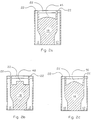
- a rectangular slider body 24 has a length L1, a width designated by reference numeral 19 and a thickness designated by numeral 28.
- the slider 24 is configured with raised side rails 10 and 12, tapered regions 22 at the leading edge of the slider and a central pad 8 formed adjacent to the central taper 22.
- the tapered regions 22 are of identical length from the leading edge.
- the tapered regions 22 have a taper angle (shown at 20 in Fig. 1a) which may be in the order of 20° to 60°.
- a negative pressure cavity 18 is formed by etching between the central pad 8 and the trailing edge of the slider.
- relief vents 30 are formed between the side rails 10, 12 and the central pad 8 and extend from the leading edge of the slider to contact the negative pressure cavity 18.
- the relief vents 30 and cavity 18 are etched preferably to the same depth which may be in the range of 100-300 microinches.
- the rails 10, 12 are symmetrically disposed on the air bearing surface of the slider.
- the rails 10, 12 have a wide portion located at the trailing edge of a length designated by reference nemeral 38, with the width being designated by reference numeral 42.
- the rails 10, 12 converge from the trailing edge wide portions by an angled section shown between the distances L3 and L2 from the leading edge.
- the narrow portions of the rails 10, 12 extend between the angled sections and the tapered regions associated with the rails and have a length which is L3 less the length of the tapered regions 22.
- the width 19 of the slider is about 63 mils (milli-inches), and the length L1 is about 80.7 mils.
- the trailing edge rail width 42 is about 15 mils and the trailing edge rail length 38 is 20.7 mils.
- the leading edge rail length 40 is 40.7 mils and the width of each leading edge rail is 6.5 mils.
- the length of the tapered regions 22 is 8 mils.
- the central pad air bearing surface is 46 mils wide and 28 mils long.
- the relief vents 30 each are 2 mils wide and the side reliefs 14 at the sides of the slider body are 1.5 mils wide.
- the etch or relief depths of the central recessed cavity 18, the relief vents 30 and the side reliefs 14 are about 200 microinches relative to the raised air bearing surfaces of side rails 10, 12 and central pad 8.
- the lengths L1, L2 and L3 are respectively about 80.7 mils, 60 mils and 50 mils.
- FIGs. 2a and 2c represent alternative embodiments of the invention wherein the central pad 46, 50 is formed with an arcuate side adjacent to the central negative pressure cavity 18.
- Figure 2b illustrates a central pad 48 having an inverted U shape adjacent to the negative pressure cavity 18.
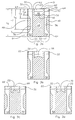
- Fig. 3a-3d illustrate other alternative embodiments in which the side rails include negative pressure regions 48 formed at the outboard portions of the side rails 52, 54, in conjunction with the different shapes of the central pads 46, 66, 68, 70.
- the dimensions of the slider body are defined by length L1 and width 19 respectively.
- Rails 52 and 54 have leading and trailing edge widths 50 and a central narrow portion of width 56.
- the angled portion of the rails closest to the leading edge is defined between L4 and L5 and the angled portion of the rails closest to the trailing edge is defined between L6 and L7.
- the leading edge of the slider has a center pad 46 following the center tapered region 22.
- the center pad 46 has a width designated by reference numeral 60 and a length designated by reference numeral 58.
- the rails 52, 54 and pad 46 follow tapered regions 22 of equal length.
- Relief vents 62 are provided adjacent to the contiguous sides of the center tapered region and the central pad 46 and extend to the central negative pressure cavity 48.
- the relief vents 62 are symmetrically disposed with relation to the side rails 52, 54 which are symmetrically disposed within the slider body relative to the longitudinal axis of the slider.
- Side reliefs 64 are provided at the side edges of the slider to realize ease of fabrication.
- the width 50 of the side tapered portions and the trailing edge sections of the rails 52, 54 is about 13 mils.
- the width of the central narrow section 56 of the rails is aboout 6 mils and the side reliefs 64 are about 1.5 mils wide.
- the overall slider length L1 is about 80.7 mils and the width of the slider is about 63 mils.
- the width 60 of the center pad 46 is about 24 mils and the length 58 of the center pad 46 is about 18 mils.
- the width of the relief vents 62 is about 5 mils each.
- the lengths further defining the dimensions of the side rails 52, 54 are about 18 mils for L4, 28 mils for L5, 60 mils for L6 and 70 mils for L7.
- the tapered regions 22 are 8 mils long and have a taper angle of 40 minutes.
- the negative pressure cavity 48 is etched to a depth of 200 microinches below the air bearing surface represented by rails 52, 54 and pad 46. Although not shown, a nominal crown of 1 ⁇ 2 microinch is provided to the air bearing surface.
- Figs. 3b through 3d illustrate alternative embodiments wherein the shapes of the central pads 66, 68, 70 are modified for specific applications of skew angle range and velocity range so that the flying height variation over these ranges is minimized.
- Fig. 4a illustrate another embodiment of a negative pressure air bearing slider wherein the magnetic transducer is located at the trailing edge and at a rear central pad 90.
- This embodiment contains two side rails 72, 74 and a central front pad 84 as well as a rear pad 90.
- the negative pressure region 92 is located aft of the central rail 84.
- the side rails 72, 74 have a length L10, which is a partial length of the total slider length L1, and a width designated as 88 at the trailing edge of the side rails and a narrow width portion 86 at the leading edge of the side rails.
- the width 86 is constant from the tapered regions 22 to a point defined by length L8, at which the rails diverge to join the wider trailing edge rail portion at a point defined by the length L9.
- the rear central pad 90 has a length shown at reference numeral 82 and a width shown at reference numeral 80.
- tapered regions 22 are provided for side rails 72, 74 and central pad 84.
- Relief vents 94 are disposed between the inboard sides of rails 72, 74 and the front central pad 84 and extend from the leading edge to the recessed cavity 92.
- Figs. 4b-4d represent alternative embodiments wherein the shapes of the central rails 98, 100, 102 are modified for specific applications of skew angle range and velocity range so that the flying height variation over these ranges is minimized.
- the rear pad 90 has a length 82 of about 10.7 mils and a width 80 of about 15 mils.
- the center pad 84 has a length 76 of about 20 mils and a width 78 of about 30 mils.
- the widths 88 of the trailing edges of the side rails 72, 74 are about 15 mils and the width at the leading edge of the side rails is about 10 mils.
- the length L8 from the leading edge of rails 72 74 at which the rail diverges is about 50 mils and the width of the rails at the trailing edge between lengths L9 and L10 is about 60 mils.
- the total rail length L10 of the side rails 72, 74 is about 70 mils.
- Side reliefs 96 are l.5 mils wide and are provided for ease of fabrication of the slider of this invention.
- the relief slots 94 are about 5 mils wide.
- Fig. 5a illustrates another embodiment of a negative pressure air bearing slider having two side rails 112, 114, a central pad 104 and a rear pad 120.
- the rear pad 120 has a trailing edge on which a magnetic transducer is disposed.
- the length of the rear pad 120 is designated by reference numeral 122 and the width is designated by reference numeral 124.
- the dimensions of the central leading edge pad 104 are designated by a length 130 and a width 132.
- the two side rails 112, 114 have a width designated by 116 at both the leading and trailing edges and are formed with a central portion of a narrower width designated by 118.
- the side rails 112, 114 have a width designated by 116 at the leading edge and trailing edge of the rails at lengths L11 and L15 respectively and a narrower portion 118 between the leading and trailing portions of the rails from length L12 to L13.
- Relief sections 126 are provided for ease of manufacturing.
- the embodiment of Fig. 4a includes negative pressure cavities 128a that are associated with each side rail 112, 114 and a central negative pressure cavity 128 that extends from the center pad 104.
- Figs. 5b-5d show modifications of the slider of Fig. 5a, wherein the center pads 106, 108, 110 are modified to accommodate different skew/velocity ranges for different applications used with negative pressure air bearing sliders of the instant invention.
- the length 122 of the rear pad 120 is about 10.7 mils and its width 124 is about 15 mils.
- the central pad 104 has a width 132 of about 20 mils and a length 130 of about 20 mils.
- the lengths of the portions of the two side rails are about 20 mils for L11, 25 mils for L12, 70 mils for L13, 60 mils for L14 and 70 mils for L15.
- the width 116 at the leading and trailing edges of the side rails is about 15 mils and the width 118 of the central portion of the side rails is about 8 mils.
- the nominal taper angle is 40 minutes and the taper length is 8 mils.
- a central negative pressure region 128 that is aft of the center pad 104 is etched to a nominal depth of about 200 microinches below the air bearing surface. Side reliefs 126 are etched to the same depth of 200 microinches.
- Fig. 6 illustrates a novel embodiment of a negative pressure slider having a single central relief vent 150 at the slider leading edge and a negative pressure cavity 140, both of the same depth.
- the central relief vent 150 acts during operation of the air bearing slider to establish an ambient pressure channel longitudinally along the center of the slider effectively dividing the negative pressure cavity 140 into two negative pressure sections 140a and 140b.
- two pads 142, 144 are disposed having the same width as the tapered sections 22.
- the widths of the two leading pads 142, 144 are designated by reference numeral 148 and extend to the inboard side of relief sections 145 from the central relief vent 150.
- the lengths of the pads 142, 144 are designated as 146.
- the width of the trailing edge portions of the rails 136, 138 is designated by 160.
- the rails 136, 138 include a narrow rectangular section 134 following the pads 142, 144. Between the rail section 134 and the trailing edge portions of the rails 136, 138, and angled section 147 is formed.
- the length L16 extends from the leading edge to the rear of the pads 142, 144.
- the narrow section 134 extends from the rear of the pads at L17 to L18 and the angled section 147 extends from L17 to L18.
- the width of the pads 142, 144 is about 28 mils and the length 146 of the pads is about 20 mils.
- the central relief vent 150 has a width of about 4 mils.
- the narrow rectangular sections 134 are 5 mils in width.
- the length L18 from the leading edge of the slider is 60 mils.
- the width 160 of the rail at the trailing edge is about 15 mils.
- the overall length L1 of the slider body is about 80.7 mils and its width is about 63 mils.
- Figs. 7 and 8 are plots that illustrate the variations in flying height and roll of a negative pressure air bearing slider, made in accordance with the configuration of Fig. 1.
- the diverging portion of rails 10 and 12 are angled at about 27° relative to the length dimension of the rails.
- L3 which is the length from the leading edge of the slider to the point of divergence of the rail structure
- the wider portion of rails 10 and 12 at the trailing edge of the slider are made shorter. In this way, the flying height of the slider and the magnetic transducer that is deposited at the trailing edge of the slider can be adjusted to accommodate different disk drive applications.
- FIG. 7 shows the mean flying height of the transducer gap measured against the length L3, where the mean flying height is defined as the average flying height over the skew angle/disk radius range of -10°/0.8 inch to +15°/1.8 inch for a disk rotation of 5400 revolutions per minute (rpm).
- Fig. 7 further illustrates the maximum change in flying height ( ⁇ microinches) over the same skew angle/disk radius range. For example, for all values of L3 the ⁇ microinches would be less than 0.2 microinch.
- Fig. 8 similarly illustrates the roll of the slider of Fig. 1 with a modification of the diverging angle of the rail portions of 45°, by way of example.
- Roll is defined as the difference in flying height between rails 10 and 12, which is positive and less than 0.4 microinch thus indicating that the rail at which the magnetic transducer is deposited on the trailing end of the slider is always the lower flying rail.
- the rail with which the DOWN transducer is associated is rail 12 whereas the UP transducer is associated with rail 10.
- the UP transducer is associated with the upper surface of a rotating magnetic disk and the DOWN transducer is associated with the lower surface of a rotating magnetic disk. It is always desirable for roll to be positive, as shown in Fig. 8 for the illustrated embodiments.
- An advantage of the invention is the simplicity and symmetry of the geometry which results in ease of manufacture and a high degree of tolerance to variations in the manufacture process.
- a major advantage is that the slider design effectively maintains the desired stable flying characteristics of the slider relative to a rotating magnetic disk.
- the novel slider design requires only a single etch step during production.
- the inventive sliders have a high degree of tolerance to manufacturing variables.
- the symmetrical design relative to the longitudinal axis of the slider allows the sliders to be used as UP or DOWN magnetic heads.
- the relief vents of this invention may have a width in the range of 1-6 milli-inches and may be etched to a depth that is 1/8 to 7/8 the depth of the central negative pressure cavity, as well as to the same depth, which may be in the range of 100-300 microinches.
- the crown on the air bearing surface of the slider may have a height of 0.5-1.5 microinches.
- the side reliefs may have a width in the range of 1-2 milli-inches.
- the rear pad shown in Figs. 5a-5d may have a width in the range of 2-8 milli-inches.
- Other modifications in dimensions or shapes may be made to the negative pressure air bearing slider having one or more relief vents within the scope of this invention.
Landscapes
- Adjustment Of The Magnetic Head Position Track Following On Tapes (AREA)
Applications Claiming Priority (2)
| Application Number | Priority Date | Filing Date | Title |
|---|---|---|---|
| US29388294A | 1994-08-19 | 1994-08-19 | |
| US293882 | 1994-08-19 |
Publications (2)
| Publication Number | Publication Date |
|---|---|
| EP0701249A2 true EP0701249A2 (de) | 1996-03-13 |
| EP0701249A3 EP0701249A3 (de) | 1996-07-17 |
Family
ID=23130973
Family Applications (1)
| Application Number | Title | Priority Date | Filing Date |
|---|---|---|---|
| EP95112971A Withdrawn EP0701249A3 (de) | 1994-08-19 | 1995-08-17 | Luftkissengelagerte Gleitkörper mit negativem Luftdruck |
Country Status (3)
| Country | Link |
|---|---|
| US (1) | US5568981A (de) |
| EP (1) | EP0701249A3 (de) |
| JP (1) | JPH08297828A (de) |
Cited By (3)
| Publication number | Priority date | Publication date | Assignee | Title |
|---|---|---|---|---|
| EP0780836A1 (de) * | 1995-12-18 | 1997-06-25 | Read-Rite Corporation | Luftdruckgelagertes Kopfgleitstück mit einem Druck unterhalb des Umgebungsdrucks |
| US5777825A (en) * | 1996-09-04 | 1998-07-07 | International Business Machines Corporation | Negative pressure step pad air bearing design and method for making the same |
| FR2763418A1 (fr) * | 1997-05-15 | 1998-11-20 | Silmag Sa | Patin de vol a surface reduite |
Families Citing this family (21)
| Publication number | Priority date | Publication date | Assignee | Title |
|---|---|---|---|---|
| JP3642821B2 (ja) * | 1995-03-17 | 2005-04-27 | 富士通株式会社 | 磁気ヘッドスライダ |
| US6760193B1 (en) * | 1995-04-07 | 2004-07-06 | Hitachi Global Storage Technologies Japan, Ltd. | Magnetic head gimbal assembly and magnetic disk unit |
| US5685645A (en) * | 1996-08-13 | 1997-11-11 | Read-Rite Corporation | Roll balance sub-ambient pressure air bearing slider |
| JP2874667B2 (ja) * | 1996-10-23 | 1999-03-24 | 日本電気株式会社 | 浮動ヘッドスライダ |
| US5704715A (en) * | 1996-12-09 | 1998-01-06 | Read-Rite Corporation | Altitude insensitive air bearing slider |
| KR19980077979A (ko) * | 1997-04-24 | 1998-11-16 | 윤종용 | 하드디스크 드라이브의 헤드 슬라이더 |
| US5986850A (en) * | 1997-06-16 | 1999-11-16 | Seagate Technology, Inc. | Positive pressure optical slider having wide center rail |
| US5872685A (en) * | 1997-08-22 | 1999-02-16 | Samsung Electronics Co., Ltd. | Flying-type negative pressure air bearing slider |
| US5917679A (en) * | 1997-08-22 | 1999-06-29 | Samsung Electronics Co., Ltd. | Pseudo contact type negative pressure air bearing slider |
| US6239951B1 (en) * | 1997-09-22 | 2001-05-29 | Seagate Technology, Llc | Air bearing slider with increased speed sensitivity |
| US6356412B1 (en) | 1999-09-30 | 2002-03-12 | Read-Rite Corporation | Air bearing facilitating load/unload of a magnetic read/write head |
| JP3808681B2 (ja) * | 2000-01-12 | 2006-08-16 | 富士通株式会社 | ディスク装置及び負圧ヘッドスライダ |
| US6870707B1 (en) | 2000-04-27 | 2005-03-22 | Seagate Technology Llc | Disc head slider having vertically contoured features and method of fabricating vertically contoured features on a slider |
| US6501621B1 (en) | 2000-11-22 | 2002-12-31 | Matsushita Kotobuki Electronics Peripherals Of America, Inc. | Air bearing slider having improved take-off velocity |
| US6646831B1 (en) | 2000-11-22 | 2003-11-11 | Matsushita Kotobuki Electronics Peripherals Of America, Inc. | Air bearing slider having optimized etch depth ratio |
| US6920015B2 (en) * | 2001-04-03 | 2005-07-19 | Seagate Technology Llc | Disc head slider designs to reduce particle sensitivity |
| US7477486B1 (en) | 2005-12-07 | 2009-01-13 | Western Digital (Fremont), Llc | Air bearing slider with a side pad having a shallow recess depth |
| US8248729B2 (en) * | 2006-11-16 | 2012-08-21 | Hitachi Global Storage Technologies, Netherlands B.V. | Slider with hook-shaped air compression mechanisms near trailing edge corners |
| US7916426B2 (en) * | 2007-11-30 | 2011-03-29 | Western Digital (Fremont), Llc | Head with an air bearing surface having left and right leading pressurizing steps, each with short and long regions |
| US8081400B1 (en) | 2008-08-29 | 2011-12-20 | Western Digital (Fremont), Llc | Slider with an air-bearing surface including four pressure generating pockets for countering disruptive movement |
| JP4937383B2 (ja) * | 2010-06-30 | 2012-05-23 | 株式会社東芝 | ヘッドおよびこれを備えたディスク装置 |
Family Cites Families (8)
| Publication number | Priority date | Publication date | Assignee | Title |
|---|---|---|---|---|
| JPH0786369B2 (ja) * | 1989-02-04 | 1995-09-20 | 豊田工機株式会社 | 角スライド静圧支承装置 |
| CA1323421C (en) * | 1989-03-17 | 1993-10-19 | Yiao-Tee Hsia | Disc drive slider configured to counteract roll |
| JPH0335469A (ja) * | 1989-06-30 | 1991-02-15 | Matsushita Electric Ind Co Ltd | ディスク駆動装置 |
| US5098204A (en) * | 1989-11-03 | 1992-03-24 | John H. Blanz Company, Inc. | Load balanced planar bearing assembly especially for a cryogenic probe station |
| JPH0636489A (ja) * | 1992-06-29 | 1994-02-10 | Read Rite Corp | 空気支持方式の磁気ヘッドスライダ |
| DE4222140C2 (de) * | 1992-07-06 | 1994-06-16 | Heinzl Joachim | Aerostatisches Miniaturlager |
| JPH0652646A (ja) * | 1992-07-30 | 1994-02-25 | Sanyo Electric Co Ltd | 浮動ヘッドスライダ |
| US5438467A (en) * | 1992-10-28 | 1995-08-01 | International Business Machines Corporation | Negative pressure air bearing design |
-
1995
- 1995-04-10 US US08/419,760 patent/US5568981A/en not_active Expired - Lifetime
- 1995-08-17 EP EP95112971A patent/EP0701249A3/de not_active Withdrawn
- 1995-08-18 JP JP7210842A patent/JPH08297828A/ja active Pending
Non-Patent Citations (1)
| Title |
|---|
| None |
Cited By (3)
| Publication number | Priority date | Publication date | Assignee | Title |
|---|---|---|---|---|
| EP0780836A1 (de) * | 1995-12-18 | 1997-06-25 | Read-Rite Corporation | Luftdruckgelagertes Kopfgleitstück mit einem Druck unterhalb des Umgebungsdrucks |
| US5777825A (en) * | 1996-09-04 | 1998-07-07 | International Business Machines Corporation | Negative pressure step pad air bearing design and method for making the same |
| FR2763418A1 (fr) * | 1997-05-15 | 1998-11-20 | Silmag Sa | Patin de vol a surface reduite |
Also Published As
| Publication number | Publication date |
|---|---|
| JPH08297828A (ja) | 1996-11-12 |
| EP0701249A3 (de) | 1996-07-17 |
| US5568981A (en) | 1996-10-29 |
Similar Documents
| Publication | Publication Date | Title |
|---|---|---|
| EP0701249A2 (de) | Luftkissengelagerte Gleitkörper mit negativem Luftdruck | |
| US4734803A (en) | Magnetic head air bearing slider | |
| US6339518B1 (en) | Air bearing slider with shaped taper | |
| US3855625A (en) | Magnetic head slider assembly | |
| EP0458444B1 (de) | Luftkissenbelagerter Kopf-Gleitkörper für Platteneinheit | |
| US5359480A (en) | Magnetic head air bearing slider | |
| US4475135A (en) | Magnetic head air bearing slider | |
| CA1129091A (en) | Magnetic head slider assembly | |
| US6771468B1 (en) | Slider with high pitch-stiffness air bearing design | |
| US5343343A (en) | Air bearing slider with relieved rail ends | |
| US4894740A (en) | Magnetic head air bearing slider | |
| US6504682B1 (en) | Disc head slider having recessed, channeled rails for reduced stiction | |
| US6411468B1 (en) | Pseudo-contact negative pressure air bearing slider with dual negative pressure pockets and central transducer | |
| US5721650A (en) | Self-loading disc head slider having blunt cross rail | |
| US5748408A (en) | Flight slider for magnetic recording | |
| US5550692A (en) | Proximity recording air bearing slider design with waist offset | |
| US5754367A (en) | Air bearing slider having etched and shaped leading edge taper | |
| EP0753843A2 (de) | Höhenunempfindlicher luftkissengelagerter Gleitkörper | |
| US6606222B1 (en) | Convergent channel, trenched disc head slider | |
| US6678119B1 (en) | Disc head slider having rails with enclosed depressions | |
| EP0622782A2 (de) | Plattenantrieb mit passivem Gleiter für mehrere Flughöhen und damit zusammenarbeitendes Plattenmuster | |
| US5704715A (en) | Altitude insensitive air bearing slider | |
| US5889634A (en) | Reduced-altitude-sensitive subambient pressure air bearing slider | |
| US6421908B1 (en) | Method of making shallow etch air bearing surface features for optimized transducer spacing | |
| US5685645A (en) | Roll balance sub-ambient pressure air bearing slider |
Legal Events
| Date | Code | Title | Description |
|---|---|---|---|
| PUAI | Public reference made under article 153(3) epc to a published international application that has entered the european phase |
Free format text: ORIGINAL CODE: 0009012 |
|
| AK | Designated contracting states |
Kind code of ref document: A2 Designated state(s): DE FR GB NL |
|
| PUAL | Search report despatched |
Free format text: ORIGINAL CODE: 0009013 |
|
| AK | Designated contracting states |
Kind code of ref document: A3 Designated state(s): DE FR GB NL |
|
| 17P | Request for examination filed |
Effective date: 19961120 |
|
| 17Q | First examination report despatched |
Effective date: 19970805 |
|
| STAA | Information on the status of an ep patent application or granted ep patent |
Free format text: STATUS: THE APPLICATION IS DEEMED TO BE WITHDRAWN |
|
| 18D | Application deemed to be withdrawn |
Effective date: 19971216 |