EP0701272A2 - Verfahren zum Herstellen einer Halbleitereinrichtung - Google Patents
Verfahren zum Herstellen einer Halbleitereinrichtung Download PDFInfo
- Publication number
- EP0701272A2 EP0701272A2 EP95112453A EP95112453A EP0701272A2 EP 0701272 A2 EP0701272 A2 EP 0701272A2 EP 95112453 A EP95112453 A EP 95112453A EP 95112453 A EP95112453 A EP 95112453A EP 0701272 A2 EP0701272 A2 EP 0701272A2
- Authority
- EP
- European Patent Office
- Prior art keywords
- layer
- resist
- gate
- forming
- gate electrode
- Prior art date
- Legal status (The legal status is an assumption and is not a legal conclusion. Google has not performed a legal analysis and makes no representation as to the accuracy of the status listed.)
- Granted
Links
Images


Classifications
-
- H—ELECTRICITY
- H10—SEMICONDUCTOR DEVICES; ELECTRIC SOLID-STATE DEVICES NOT OTHERWISE PROVIDED FOR
- H10D—INORGANIC ELECTRIC SEMICONDUCTOR DEVICES
- H10D30/00—Field-effect transistors [FET]
- H10D30/01—Manufacture or treatment
- H10D30/061—Manufacture or treatment of FETs having Schottky gates
- H10D30/0612—Manufacture or treatment of FETs having Schottky gates of lateral single-gate Schottky FETs
-
- H—ELECTRICITY
- H10—SEMICONDUCTOR DEVICES; ELECTRIC SOLID-STATE DEVICES NOT OTHERWISE PROVIDED FOR
- H10D—INORGANIC ELECTRIC SEMICONDUCTOR DEVICES
- H10D64/00—Electrodes of devices having potential barriers
- H10D64/01—Manufacture or treatment
- H10D64/012—Manufacture or treatment of electrodes comprising a Schottky barrier to a semiconductor
- H10D64/0124—Manufacture or treatment of electrodes comprising a Schottky barrier to a semiconductor to Group III-V semiconductors
- H10D64/0125—Manufacture or treatment of electrodes comprising a Schottky barrier to a semiconductor to Group III-V semiconductors characterised by the sectional shape, e.g. T or inverted T
-
- H—ELECTRICITY
- H10—SEMICONDUCTOR DEVICES; ELECTRIC SOLID-STATE DEVICES NOT OTHERWISE PROVIDED FOR
- H10P—GENERIC PROCESSES OR APPARATUS FOR THE MANUFACTURE OR TREATMENT OF DEVICES COVERED BY CLASS H10
- H10P76/00—Manufacture or treatment of masks on semiconductor bodies, e.g. by lithography or photolithography
- H10P76/20—Manufacture or treatment of masks on semiconductor bodies, e.g. by lithography or photolithography of masks comprising organic materials
- H10P76/202—Manufacture or treatment of masks on semiconductor bodies, e.g. by lithography or photolithography of masks comprising organic materials for lift-off processes
Definitions
- the present invention relates to a method of making a semiconductor device, particularly to a method of making a gate electrode of a field-effect transistor.
- FET field-transistor
- Rg gate resistance
- Rs source resistance
- Cgs source-gate capacitance
- gm mutual conductance
- FIG. 13 An outline of manufacturing steps are shown in Figure 13 and Figure 14.
- a two-stage exposure is performed by using an electron beam 23a and an electron beam 23b of which intensities are different to form a post 27a and a cap 27b of a mushroom-type gate electrode 27 in a resist 22 for electron beam coated on the surface of a semiconductor substrate 21.
- the resist 22 is developed, a mushroom shape 23 is formed in the resist 22 on which a gate metal is deposited by evaporation and the resist 22 is lifted off by which the mushroom-type gate electrode 27 is provided as shown in Figure 14.
- the conventional EB exposure device is provided with a poor throughput and a high apparatus cost and therefore, the product cost is enhanced.
- a method of making a semiconductor device having a Schottky gate on a semiconductor substrate including;
- step 1 is composed of the following step.
- a method of making a semiconductor device having a Schottky gate electrode on a semiconductor substrate including:
- a sub half micron meter gate electrode can stably be formed with a high throughput. Further, it is not necessary to remove the second layer of the resist in later steps and therefore, the steps can be shortened and the manufacturing cost can be reduced.
- the mushroom-type gate electrode or the ⁇ -type gate electrode can be formed by a single vapor deposition and therefore, the steps can be shortened, the cost for used material can be restrained and the manufacturing cost can be reduced.
- the cap of the mushroom-type gate electrode or the eaves of the ⁇ -type gate electrode is separately exposed and therefore, the cap or the eaves can be formed offset from the post of the gate electrode, the interval between the source and the gate can be narrowed while maintaining low the gate resistance (Rg) and the source-gate capacitance (Cgs) and the source resistance (Rs) can be reduced.
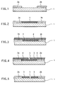
- numeral 1 designates a semiconductor substrate and an activated layer (not shown) is formed on the surface of the semiconductor substrate 1.
- a source electrode 2a and a drain electrode 2b are formed on the semiconductor substrate 1 on which the activated layer has been formed, in an ohmic contact therebetween.
- a first layer of an insulative layer 3 of a resist having a thickness that is equal to or more than those of the source electrode 2a and the drain electrode 2b is spincoated in a gate electrode forming region between the source electrode 2a and the drain electrode 2b and is flattened. Further, the first layer of the insulative film 3 is etched back by reactive ion etching (RIE), a milling apparatus etc.
- RIE reactive ion etching
- a second layer of a resist 4 for gate patterning is spincoated.
- the film thickness of the second layer of a resist 4 is set to a film thickness showing an excellent exposure sensitivity for an i-line stepper.
- a treatment by baking at high temperatures, for example, 200°C or by CF4 plasma may be performed on the first layer of the insulative film 3.
- a gate pattern 5 is exposed on the second layer of the resist 4 and is developed.
- the gate pattern 5 is transcribed in the first layer of the insulative film 3 while etching the second layer of the resist 4 under an anisotropic etching condition.
- an anisotropic etching utilizing accumulated substances on the side wall may be used.
- it is an etching using a fluorocarbon group gas by RIE.
- a resist reflow (heating in an oven at 200°C for 30 minutes) is performed to round corners 3b of the gate pattern 5 of the first layer of the insulative film 3. These steps are performed to avoid disconnection by rounding a portion of a mushroom-type gate electrode in connection with a stand and a cap thereof (which corresponds to the corner portions 3b which are to be formed).
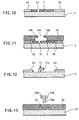
- a third layer of a resist 6 is coated for forming the cap of the mushroom-type gate electrode.
- An opening 6a is formed by performing exposure and development.
- Eaves 6b may be formed by chlorobenzene treatment or a multi-layer resist method to facilitate the lifting-off.
- a gate metal is deposited by evaporation and the first layer of an insulative film 3 and the third layer of a resist 6 and unnecessary deposited metals thereon are lifted off thereby forming a mushroom-type gate electrode 7.
- a silicon nitride (SiNx) film or a silicon oxide (SiO2) film having a thickness approximately equal to those of the source electrode 2a and the drain electrode 2b may be formed in the gate electrode forming region as the first layer of the insulative film 3 composed of a single layer or a multi-layer structure by a film forming means such as sputtering, vapor deposition, chemical vapor deposition (CVD) etc.
- a film forming means such as sputtering, vapor deposition, chemical vapor deposition (CVD) etc.
- an interval between a source and a gate is often made narrower than that between a drain and the gate to improve noise characteristic.
- the interval between a one-side portion of a cap of the mushroom-type gate electrode and a source electrode becomes narrow whereby the source-gate capacitance (Cgs) may not be negligible.
- this embodiment solves the problem by providing a ⁇ -type gate electrode in which a source side portion of a cap of the mushroom-type gate electrode is dispensed with and an eaves is provided only on the side of the drain.
- the second layer of the resist 4 is etched and at the same time the gate pattern 15 is transcribed in the first layer of the insulative film 3 under an anisotropic etching condition.
- a third layer of a resist 16 is coated for forming a ⁇ -type gate electrode. Further, an opening 16a that is dislocated to the side of the drain electrode 2b with respect to the gate pattern 15 is exposed and developed. Eaves 16b may be formed by a chlorobenzene treatment or a multi-layer resist method to facilitate the lifting-off.
- a gate metal is deposited by evaporation. Further, the first layer of the insulative film 3 and the third layer of the resist 16 and unnecessary deposited metals thereon are lifted off thereby forming a ⁇ -type gate electrode 17 having an eaves 17a on the side of the drain electrode.
- a sub half micron meter gate electrode can stably be formed with a high throughput since exposure is performed on the flat first layer of the insulative film. Further, it is not necessary to remove the second layer of the resist in later steps and therefore, the steps can be shortened and the manufacturing cost can be reduced. Further, a mushroom-type gate electrode or a ⁇ -type gate electrode can be formed by a single step of vapor deposition and therefore, the steps can be shortened, used material can be saved and the manufacturing cost can be reduced.
- the cap of the mushroom-type gate electrode or the eaves of the ⁇ -type gate electrode is separately exposed and therefore, the interval between the source and the gate can be narrowed and the source resistance (Rs) can be reduced while maintaining low the gate resistance (Rg) and the source-gate capacitance (Cgs) by offsetting the cap or the eaves with respect to the post of the gate electrode.
Landscapes
- Junction Field-Effect Transistors (AREA)
Applications Claiming Priority (2)
| Application Number | Priority Date | Filing Date | Title |
|---|---|---|---|
| JP217513/94 | 1994-09-12 | ||
| JP06217513A JP3077524B2 (ja) | 1994-09-12 | 1994-09-12 | 半導体装置の製造方法 |
Publications (3)
| Publication Number | Publication Date |
|---|---|
| EP0701272A2 true EP0701272A2 (de) | 1996-03-13 |
| EP0701272A3 EP0701272A3 (de) | 1996-03-27 |
| EP0701272B1 EP0701272B1 (de) | 1998-12-16 |
Family
ID=16705414
Family Applications (1)
| Application Number | Title | Priority Date | Filing Date |
|---|---|---|---|
| EP95112453A Expired - Lifetime EP0701272B1 (de) | 1994-09-12 | 1995-08-08 | Verfahren zum Herstellen einer Halbleitereinrichtung |
Country Status (6)
| Country | Link |
|---|---|
| US (1) | US5712175A (de) |
| EP (1) | EP0701272B1 (de) |
| JP (1) | JP3077524B2 (de) |
| KR (1) | KR100195293B1 (de) |
| DE (1) | DE69506646T2 (de) |
| FI (1) | FI110642B (de) |
Cited By (2)
| Publication number | Priority date | Publication date | Assignee | Title |
|---|---|---|---|---|
| EP0801418A3 (de) * | 1996-04-10 | 1998-07-29 | Murata Manufacturing Co., Ltd. | Herstellungsverfahren einer T-förmigen Gate-Elektrode in einem Halbleiterbauelement, und die T-förmige Gate-Elektrode |
| CN113097307A (zh) * | 2021-03-31 | 2021-07-09 | 浙江集迈科微电子有限公司 | GaN器件结构及其制备方法 |
Families Citing this family (13)
| Publication number | Priority date | Publication date | Assignee | Title |
|---|---|---|---|---|
| JP2780704B2 (ja) * | 1996-06-14 | 1998-07-30 | 日本電気株式会社 | 半導体装置の製造方法 |
| JP4093395B2 (ja) * | 2001-08-03 | 2008-06-04 | 富士通株式会社 | 半導体装置とその製造方法 |
| TW569077B (en) * | 2003-05-13 | 2004-01-01 | Univ Nat Chiao Tung | Method for fabricating nanometer gate in semiconductor device using thermally reflowed resist technology |
| US8878245B2 (en) | 2006-11-30 | 2014-11-04 | Cree, Inc. | Transistors and method for making ohmic contact to transistors |
| US9634191B2 (en) | 2007-11-14 | 2017-04-25 | Cree, Inc. | Wire bond free wafer level LED |
| US8368100B2 (en) * | 2007-11-14 | 2013-02-05 | Cree, Inc. | Semiconductor light emitting diodes having reflective structures and methods of fabricating same |
| US8384115B2 (en) * | 2008-08-01 | 2013-02-26 | Cree, Inc. | Bond pad design for enhancing light extraction from LED chips |
| US8741715B2 (en) * | 2009-04-29 | 2014-06-03 | Cree, Inc. | Gate electrodes for millimeter-wave operation and methods of fabrication |
| JP5521447B2 (ja) * | 2009-09-07 | 2014-06-11 | 富士通株式会社 | 半導体装置の製造方法 |
| US9070851B2 (en) | 2010-09-24 | 2015-06-30 | Seoul Semiconductor Co., Ltd. | Wafer-level light emitting diode package and method of fabricating the same |
| USD826871S1 (en) | 2014-12-11 | 2018-08-28 | Cree, Inc. | Light emitting diode device |
| CN205944139U (zh) | 2016-03-30 | 2017-02-08 | 首尔伟傲世有限公司 | 紫外线发光二极管封装件以及包含此的发光二极管模块 |
| US11302786B2 (en) * | 2019-04-04 | 2022-04-12 | Hrl Laboratories Llc | Miniature field plate T-gate and method of fabricating the same |
Family Cites Families (7)
| Publication number | Priority date | Publication date | Assignee | Title |
|---|---|---|---|---|
| JPS59135773A (ja) * | 1983-01-24 | 1984-08-04 | Nec Corp | 半導体装置の製造方法 |
| US4959326A (en) * | 1988-12-22 | 1990-09-25 | Siemens Aktiengesellschaft | Fabricating T-gate MESFETS employing double exposure, double develop techniques |
| JPH0414212A (ja) * | 1990-05-02 | 1992-01-20 | Dainippon Printing Co Ltd | レジストパターン形成方法 |
| FR2663155B1 (fr) * | 1990-06-12 | 1997-01-24 | Thomson Composants Microondes | Procede de realisation d'une grille de transistor. |
| US5147812A (en) * | 1992-04-01 | 1992-09-15 | Motorola, Inc. | Fabrication method for a sub-micron geometry semiconductor device |
| DE4228836A1 (de) * | 1992-08-29 | 1994-03-03 | Daimler Benz Ag | Selbstjustierendes Verfahren zur Herstellung von Feldeffekttransistoren |
| JP3082469B2 (ja) * | 1992-09-22 | 2000-08-28 | 株式会社村田製作所 | ゲート電極の形成方法 |
-
1994
- 1994-09-12 JP JP06217513A patent/JP3077524B2/ja not_active Expired - Fee Related
-
1995
- 1995-08-08 EP EP95112453A patent/EP0701272B1/de not_active Expired - Lifetime
- 1995-08-08 DE DE69506646T patent/DE69506646T2/de not_active Expired - Fee Related
- 1995-09-06 US US08/524,208 patent/US5712175A/en not_active Expired - Fee Related
- 1995-09-07 KR KR1019950029368A patent/KR100195293B1/ko not_active Expired - Fee Related
- 1995-09-11 FI FI954241A patent/FI110642B/fi active
Cited By (3)
| Publication number | Priority date | Publication date | Assignee | Title |
|---|---|---|---|---|
| EP0801418A3 (de) * | 1996-04-10 | 1998-07-29 | Murata Manufacturing Co., Ltd. | Herstellungsverfahren einer T-förmigen Gate-Elektrode in einem Halbleiterbauelement, und die T-förmige Gate-Elektrode |
| CN113097307A (zh) * | 2021-03-31 | 2021-07-09 | 浙江集迈科微电子有限公司 | GaN器件结构及其制备方法 |
| CN113097307B (zh) * | 2021-03-31 | 2022-07-19 | 浙江集迈科微电子有限公司 | GaN器件结构及其制备方法 |
Also Published As
| Publication number | Publication date |
|---|---|
| DE69506646D1 (de) | 1999-01-28 |
| JPH0883809A (ja) | 1996-03-26 |
| DE69506646T2 (de) | 1999-06-17 |
| KR960012550A (ko) | 1996-04-20 |
| FI110642B (fi) | 2003-02-28 |
| FI954241A0 (fi) | 1995-09-11 |
| EP0701272B1 (de) | 1998-12-16 |
| JP3077524B2 (ja) | 2000-08-14 |
| EP0701272A3 (de) | 1996-03-27 |
| KR100195293B1 (ko) | 1999-06-15 |
| FI954241L (fi) | 1996-03-13 |
| US5712175A (en) | 1998-01-27 |
Similar Documents
| Publication | Publication Date | Title |
|---|---|---|
| EP0701272B1 (de) | Verfahren zum Herstellen einer Halbleitereinrichtung | |
| US4746628A (en) | Method for making a thin film transistor | |
| EP0801418B1 (de) | Herstellungsverfahren einer T-förmigen Gate-Elektrode in einem Halbleiterbauelement, und die T-förmige Gate-Elektrode | |
| US6107640A (en) | Semiconductor device for a thin film transistor | |
| US5942767A (en) | Thin film transistors including silicide layer and multilayer conductive electrodes | |
| JP2809826B2 (ja) | 半導体装置の製造方法 | |
| EP0449404B1 (de) | Verfahren zur Herstellung eines Dünnschicht-Halbleiterbauteils auf einem transparenten, isolierenden Substrat | |
| US20060270162A1 (en) | High voltage metal-oxide-semiconductor transistor devices and method of making the same | |
| JPH06310492A (ja) | チタン系薄膜のエッチング液及び半導体装置の製造方法 | |
| GB2222308A (en) | A method of producing a semiconductor device | |
| KR100228385B1 (ko) | 반도체 소자의 게이트 전극 제조 방법 | |
| JPH07176544A (ja) | 半導体装置およびその製造方法 | |
| JPS59175726A (ja) | 半導体装置の製造方法 | |
| Weitzel et al. | A review of GaAs MESFET gate electrode fabrication technologies | |
| KR100303767B1 (ko) | 미세한 레지스트 패턴의 형성 방법 및 게이트 전극의 형성 방법 | |
| KR100705616B1 (ko) | 박막트랜지스터 액정표시장치의 제조방법 | |
| KR100476047B1 (ko) | 에프.에프.에스 모드의 액정표시장치의 제조방법 | |
| US20060079036A1 (en) | Method of manufacturing gate, thin film transistor and pixel | |
| KR100223917B1 (ko) | 모스 트랜지스터의 구조 | |
| JPS6144473A (ja) | 半導体装置の製造方法 | |
| JPH065562A (ja) | 半導体薄膜の形成方法 | |
| JPH0653494A (ja) | 半導体装置 | |
| KR0172249B1 (ko) | 반도체소자의 콘택홀 형성방법 | |
| JPH0290538A (ja) | 半導体装置の製造方法 | |
| JPH10313092A (ja) | 半導体装置及びその製造方法 |
Legal Events
| Date | Code | Title | Description |
|---|---|---|---|
| PUAI | Public reference made under article 153(3) epc to a published international application that has entered the european phase |
Free format text: ORIGINAL CODE: 0009012 |
|
| PUAL | Search report despatched |
Free format text: ORIGINAL CODE: 0009013 |
|
| AK | Designated contracting states |
Kind code of ref document: A2 Designated state(s): DE FR GB SE |
|
| AK | Designated contracting states |
Kind code of ref document: A3 Designated state(s): DE FR GB SE |
|
| 17P | Request for examination filed |
Effective date: 19960624 |
|
| 17Q | First examination report despatched |
Effective date: 19970521 |
|
| GRAG | Despatch of communication of intention to grant |
Free format text: ORIGINAL CODE: EPIDOS AGRA |
|
| GRAG | Despatch of communication of intention to grant |
Free format text: ORIGINAL CODE: EPIDOS AGRA |
|
| GRAH | Despatch of communication of intention to grant a patent |
Free format text: ORIGINAL CODE: EPIDOS IGRA |
|
| GRAH | Despatch of communication of intention to grant a patent |
Free format text: ORIGINAL CODE: EPIDOS IGRA |
|
| GRAA | (expected) grant |
Free format text: ORIGINAL CODE: 0009210 |
|
| AK | Designated contracting states |
Kind code of ref document: B1 Designated state(s): DE FR GB SE |
|
| REF | Corresponds to: |
Ref document number: 69506646 Country of ref document: DE Date of ref document: 19990128 |
|
| ET | Fr: translation filed | ||
| PLBE | No opposition filed within time limit |
Free format text: ORIGINAL CODE: 0009261 |
|
| STAA | Information on the status of an ep patent application or granted ep patent |
Free format text: STATUS: NO OPPOSITION FILED WITHIN TIME LIMIT |
|
| 26N | No opposition filed | ||
| REG | Reference to a national code |
Ref country code: GB Ref legal event code: IF02 |
|
| PGFP | Annual fee paid to national office [announced via postgrant information from national office to epo] |
Ref country code: DE Payment date: 20080821 Year of fee payment: 14 |
|
| PGFP | Annual fee paid to national office [announced via postgrant information from national office to epo] |
Ref country code: FR Payment date: 20080818 Year of fee payment: 14 |
|
| PGFP | Annual fee paid to national office [announced via postgrant information from national office to epo] |
Ref country code: GB Payment date: 20080820 Year of fee payment: 14 |
|
| PGFP | Annual fee paid to national office [announced via postgrant information from national office to epo] |
Ref country code: SE Payment date: 20080807 Year of fee payment: 14 |
|
| GBPC | Gb: european patent ceased through non-payment of renewal fee |
Effective date: 20090808 |
|
| REG | Reference to a national code |
Ref country code: FR Ref legal event code: ST Effective date: 20100430 |
|
| PG25 | Lapsed in a contracting state [announced via postgrant information from national office to epo] |
Ref country code: FR Free format text: LAPSE BECAUSE OF NON-PAYMENT OF DUE FEES Effective date: 20090831 Ref country code: DE Free format text: LAPSE BECAUSE OF NON-PAYMENT OF DUE FEES Effective date: 20100302 |
|
| PG25 | Lapsed in a contracting state [announced via postgrant information from national office to epo] |
Ref country code: GB Free format text: LAPSE BECAUSE OF NON-PAYMENT OF DUE FEES Effective date: 20090808 |
|
| PG25 | Lapsed in a contracting state [announced via postgrant information from national office to epo] |
Ref country code: SE Free format text: LAPSE BECAUSE OF NON-PAYMENT OF DUE FEES Effective date: 20090809 |